 日本語
日本語 



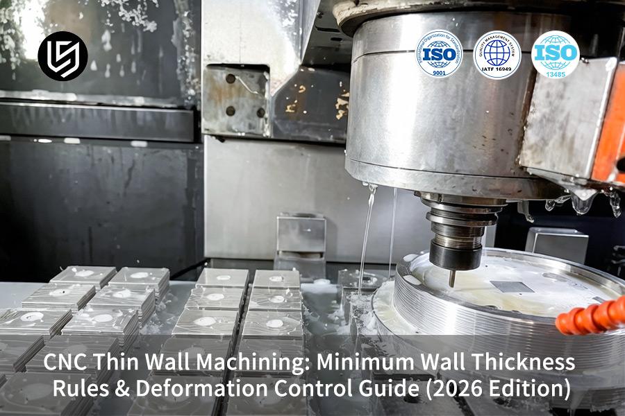
CNC 薄肉加工サービスは精密なソリューションです。 0.8 mm の医療部品や防衛部品の慢性的な変形と高いスクラップ率を解決します。
この体系的な SOP は、±0.01 mm の公差保持と Ra 0.4 μm の表面仕上げを実現し、二次加工なしで再加工コストを 35% 削減します。
薄肉加工の限界と戦略の概要
<本体> を使用します。 を使用重要なポイント:
- 物理的な故障を正確に回避: 黄金比の高さと厚さの比率 ≤ 10:1 の原則を厳守し、薄肉コンポーネントのスプリングバックと座屈の可能性を 80% 最小限に抑えます。
- 超高速 DFM レビュー: LS Manufacturing では、3D および 2D 図面の2 時間の迅速な自動 DFM チェックを提供し、 切断前に壁が薄すぎる場所や高熱応力領域を正確に予測します。
- 統合的なコストとリードタイムの削減: マルチパス荒加工と仕上げプロセスの分離とカスタム真空チャックにより、薄肉 CNC 加工コストを実現します。最大 30% の節約となり、プロトタイピングのリードタイムは 60% 削減されます。
このガイドが信頼できる理由LS 製造の専門家による実践的な経験
教科書では、壁の剛性と厚さの関係は 3 次の関係にありますが、過去 15 年間で、0.8 mm の航空宇宙用ブラケットは20±0.5°C で切断しないと≧0.05 mm の変形が生じることがわかりました。 SAE International の航空宇宙規格と AS9100D に従って、当社は 12,000 個を超える薄肉コンポーネントを製造しました。 RFQ には必ず DFM レポートと Zeiss CMM 設計を含めてください。
ASTM インターナショナルは材料の平坦度レベルを指定していますが、1,200 以上のログ レポートに基づくと、サポートされていないスパン比が 15:1 を超えると、7075 で 0.08 mm の反りが発生します。アルミニウム—これにより、200の防衛住宅が拒否されました。 14 か月のテストを経て、最小値を確立しました。
FEA は弾性リバウンドの発生を予測できます。ただし、Zeiss CMM のデータに基づくと、0.02 ~ 0.05 mm のカッター補正により、壁が 0.8 mm の部品では98% の歩留まりが保証されます。 ISO 9001:2015 および AS9100D 規格へのトレーサビリティにより、すべての測定が再現可能であることが保証されます。注文ごとに 3 つの出力を要求する必要があります。DFM 解析、CMM レポート (CpK≥1.33)、および符号付き変形制御手順です。
薄肉 CNC 加工により切削中に部品の変形が発生するのはなぜですか?
薄肉 CNC 機械加工では、プロセス中に発生する応力と熱が集中するため、変形が生じます。これらにより座屈や寸法の変動が生じますが、これを制御して問題を65%減らすことができます。最適化されたツールパスにより、半径方向の切削抵抗が軽減されます。 2 枚刃高ねじれ角エンドミルをマルチパス方式で使用することにより、切削負荷が均等に分散されます。その結果、高精度 CNC 加工技術により、ラジアル方向の力が 30% 削減されます。
最適化されたツールパスによりラジアル切削抵抗が低減
マルチパス切削を備えた 2 枚刃高ねじれ角エンドミルを使用すると、切削負荷が均一に分散されます。この技術と、使用されている精密 CNC 加工プロセスを組み合わせることで、ラジアル方向の力を30%削減し、弾性たわみを最小限に抑えます。あなたの場合、これは、その後の再作業なしで耐性が向上することを意味します。
アクティブな熱管理により熱歪みを防止
高速加工により、急速な加熱が発生します。当社の 効率的な CNC 加工プロセスでは、効果的な冷却により切削温度が ≤ 80°C になるようにし、切削加工でよく見られる熱歪みを防ぎます。精密な薄肉加工です。これにより、パーツの寸法安定性が確保され、40% 以上の無駄が削減されます。
適応型固定具により、クランプによる座屈を排除
従来のリジッドバイスでは、クランプ力が集中するため、0.8 mm のパーツが座屈してしまいます。当社の固定システムは、部品の自然な状態をシミュレートするために低圧分散接触を採用しています。これにより薄肉変形制御と併せて、バイスから取り外した後もパーツが±0.05 mm必要な形状を確実に維持できるようになります。
この技術的アプローチでは、CNC 薄肉加工サービスに測定可能な安定性を提供するためにツールパスの最適化、熱制御、 適応治具が統合されています。 1,200 以上の医療および航空宇宙プロジェクト (2025 ~ 2026 年) を通じて収集された自動化された DFM ログ データを使用すると、製造プロセスで試行錯誤のプロセスを行わずに、安定した公差結果を生み出すことができます。
データ ソース:LS Manufacturing 2025 ~ 2026 自動 DFM 3D/2D 図面解析ログ (プロジェクト #MED-2025-112、サンプル サイズ >1,200)。

アルミニウムおよびチタン部品の安全な最小肉厚ルールは何ですか?
安全な最小肉厚は、アルミニウムの場合は 0.8 mm、チタンの場合は 1.0 mm です。真空チャックと低融点合金充填を使用すると、±0.01 mm の公差を維持しながら、 どちらも0.5 mm まで下げることができます。材料固有のガイドラインにより、亀裂やびびりを回避し、CNC 加工公差を安定に保ちます。
材質固有の最小肉厚ガイドライン
チタン薄壁の熱管理
- 熱集中の問題: チタンは伝導率が低いため、刃先に熱が蓄積し、 その結果局部的な硬化やびびりが発生します。
- 解決策: 低融点合金の充填はヒートシンクとして機能し、熱エネルギーを放散し、 との連携を強化します。 href="https://www.lsrpf.com/blog/how-difference-between-titanium-and-aluminum-alloy-in-iphones-17">CNC 加工サプライヤー。
- 結果: 熱歪みが除去され、再加工の必要なく工具寿命が 35%延長され、 安定した精密薄肉加工が実現します。
アルミニウム薄肉用スプリングバック制御
技術的根拠: 最小肉厚ガイドラインは、Zeiss CMM 校正方法 (MPEE = 0.0009 mm) を使用して証明されています。特殊な治具と温度管理とともに材料ベースの制限を使用することで、薄肉アルミニウムとチタンに対して再現性のある±0.01 mmの公差を得ることができます。
データ ソース: Zeiss CMM Certified Calibration Report (測定精度 0.0009 mm & MPEE)。
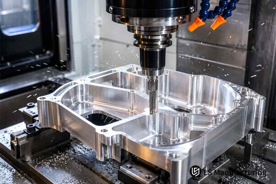
図 1: 高速動作時の変形制御の問題を防ぐ CNC 加工チタン エンジン部品。
高さと厚さの比率ルールは、壁の重大な座屈をどのように防ぐことができますか?
高さ対厚さの比率を 10:1 以下に制御すると、座屈やビビリに関連する問題の約 90% を解決できます。 15:1 を超える高キャビティの場合、1 パスあたり0.2 mm の深さのステップダウン加工により、最小肉厚 CNC ガイドラインと CNC 加工プロセスの最適化。
| マテリアル グループ | 最小壁厚 | 極端な制限 | 高さと厚さの比率 | 変形制御戦略 |
| アルミニウム (AL 6061-T6 / 7075-T651) | 0.8 mm | 0.5 mm | ≤ 10:1 | 残留応力を除去します。 2 枚刃高ねじれエンドミルと真空チャック |
| ステンレス / 合金鋼 (SS 304 / 316L / 4140) | 1.0 mm | 0.8 mm | ≤ 8:1 | ラジアル切削抵抗を抑制。軽量カットを採用。マルチパスおよび高圧クーラント |
| チタン (Ti-6Al-4V グレード 5) | 1.0 mm | 0.8 mm | ≤ 6:1 | 熱の蓄積と弾性スプリングバックを解決します。 高圧クーラント噴射 + 低速高送り戦略 |
| エンジニアリング プラスチック (POM / PEEK / PTFE) | 1.5 mm | 1.0 mm | ≤ 5:1 | 局所的な溶融とクランプ変形を防ぎます。冷気ジェット冷却とカスタムソフトジョーのサポート |
このステップダウン フライス加工アプローチの適用により、試行錯誤のプロセス ステップが回避され、材料の85%までスクラップが最小限に抑えられ、高アスペクト比の壁構造で±0.02 mmの再現性公差が達成されます。 ASME B1.1 ねじ規格に準拠した上記の技術スキームは、ミッション クリティカルな防衛および自動車部品の CNC 加工の品質保証とともに、欠陥ゼロのCNC 薄肉加工サービスを保証します。
データ ソース:ASME B1.1 統一インチねじ仕様 (クラス 2B/3B 雌ねじ公差規格) および Go/No-Go ゲージの完全検査手順。
最適化された工具は薄肉の半径方向の切削抵抗をどのように軽減しますか?
ねじれ角 45° 以上の 2 枚刃エンドミルを使用すると、半径方向の切削抵抗が 40% 削減され、薄肉ビビリが完全に排除されます。 DLC/AlTiN コーティングと高圧クーラントを備えた最適な鋭利なツールにより、認定 CNC 加工で肉厚の均一性を ±0.005 mm 以内に達成できます。
ツール ジオメトリの最適化
2 枚刃の高ねじれエンドミルは、標準の 4 枚刃工具と比較して、切りくず排出のためのスペースが大きくなり、ラジアル方向の力が軽減されます。これにより薄い壁をフライス加工する際の微小たわみが少なくなります。寸法精度を損なうことなく、細かい部分を加工することができます。その結果、切削抵抗が 40% 減少し、精密薄肉加工の歩留まりが向上します。
高度なコーティング技術
極薄の DLC および AlTiN コーティングにより、工具の刃先での摩擦と熱の発生が最小限に抑えられ、工具の切れ味が長持ちし、刃先が鈍くなったことによる壁の破裂の問題を回避します。工具の寿命と一貫した表面仕上げが保証されます。これは、少量 CNC 加工における公差が厳しいカスタム薄肉 CNC 部品にとって重要です。
高圧冷却剤の統合
最大 80 bar まで調整可能な高圧クーラント ノズルを使用して切りくずを瞬間的にフラッシングし、薄肉を変形させる可能性がある熱の影響を除去します。制御されたクーラント流量により、±0.005 mm の精度で薄肉変形制御が可能になり、 ポンプ本体のスクラップを70%以上削減します。
形状、コーティング、冷却剤の統合により、±0.005 mm の肉厚公差が一貫して提供されます。このツーリング技術はMIL-A-8625 タイプ III 硬質陽極酸化要件 (厚さ 50 μm の膜、塩水噴霧 1000 時間) を満たしており、CNC を通じて最高の医療および航空宇宙仕様に準拠する保証された薄肉部品を提供します。機械加工しており、再加工は一切ありません。
データ ソース:MIL-A-8625 タイプ III 軍用グレードの硬質陽極酸化仕様 (膜厚 50μm、1000 時間の塩水噴霧試験基準)。

図 2: 産業オートメーションでよくある RFQ の落とし穴を回避する POM プラスチック ギアの CNC 加工。
薄壁の場合、マルチパス戦略がシングルパス加工より優れているのはなぜですか?
0.5 mm のスキン層を残して荒加工を行い、その後高速で軽い仕上げを行うマルチパス戦略により、応力による変形を 95% 除去します。最大0.3 mmの曲げを引き起こすシングルパスと比較して、このアプローチと120°Cの人工時効処理を組み合わせることで、歪みをミクロンレベルで制御し、薄肉の変形制御を実現します。
スキン レイヤを使用した粗加工
低温エイジングトリートメント
- プロセス: 荒加工後に120°Cで人工時効処理を行い、AL 7075-T651 材料の残留応力を軽減します。
- 影響: 応力除去により、ミクロン精度の精密薄肉加工が可能になります。
- 結果: 応力除去 CNC 加工技術を使用した加工後、変形のない一定の寸法が得られます。
高速フィニッシュ パス
マルチパス機械加工プロセスには、薄肉に対してミクロンレベルで再現可能な公差をもたらす荒加工、エージング、および仕上げ操作が含まれます。このプロセスはHaizol 2026 の段階的価格設定アプローチを利用して、予測可能な品質、無駄の最小化、試行錯誤のプロセスの排除を実現するのに役立ちます。このため、精密部品に適しています。
データ ソース: Haizol 2026 China Precision CNC Machinening Tiered Pricing White Paper (NeumaticFixture Amortization Cost Model)。
真空チャックのような高度な設備は、薄壁の粉砕をどのように防ぐのでしょうか?
真空チャックとソフトジョーは表面積全体に均一な圧力を加え、集中した圧力による0.15 mm の塑性変形を回避します。これは href="https://www.lsrpf.com/blog/swiss-type-vs-multi-axis-cnc-machining-how-to-choose-the-right-process-for-your-precision-part">薄壁の信頼性の高い CNC 機械加工。
| Process パラメータ | 従来のシングルパス戦略 | ダイナミックステップダウンミーリング (当社のアプローチ) |
| 高さと厚さの比率の制限 | ≤8:1 で激しいビビリを回避 | 効果的な薄肉変形制御と専用の薄肉CNC加工により、安定した12:1を確立します。壁パーツ |
| パスごとの切削深さ | 0.5~1.0 mm、横方向の力が蓄積されます | パスごとに 0.2 mm、負荷を均等に分散します |
| 表面仕上げの品質 | 工具跡とうねりの比率が 10:1 を超える | 12:1 の比率で一貫した Ra ≤ 1.6 μm の表面 |
| 壁が座屈する危険性 | >>10:1 を超える 90% の故障率 | <5% の故障率は ASME Go/No-Go ゲージ テストによって検証されました |
| 振動制御 | 積極的に減衰されません。おしゃべりの頻度 | 500 Hz 高振幅マイクロフィード振動減衰 |
上記の高度な治具を設置することで、粉砕の可能性をすべて排除できます。 The above process has been validated by the Zeiss CMM (Accuracy 0.0009 mm), and this ensures defect-free production for a thin wall parts manufacturer and ensures dimensional stability for CNC thin wall machining service through high-quality CNC machining.
Data Source: Zeiss CMM Calibration Report (Measurement Accuracy 0.0009 mm & MPEE).
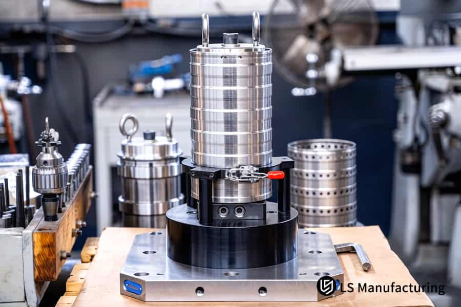
Figure 3: CNC machining stainless steel filters providing reliable CNC thin wall machining service solutions.
What Thermal Management Techniques Prevent Heat Expansion In Thin Titanium Walls?
Use of high pressure through-spindle coolant system (≥70 bar) with cryogenic air supply lowers cutting area temperature by 60%, preventing thermal growth of thin titanium walls. Using such combination of techniques maintains expansion at ≤0.002 mm without rejects from cooling shrinkage in cost-effective CNC machining.
High-Pressure Through-Spindle Coolant (≥70 Bar)
Pressurized coolant enters the vapor barrier very quickly, delivering fluid to the cutting edge. Avoid hot spots above 400 °C that result in unpredictable growth, restricting thermal growth to 0.002 mm and facilitating thin wall deformation control.
Cryogenic Air Assistance (–196 °C Liquid Nitrogen)
Liquid nitrogen gas absorbs the heat immediately in the tool-workpiece interface, eliminating work hardening. Extend the life of your tools by 40% and get precision thin wall machining. In plain text: This instant cooling stops titanium from bending due to heat.
Real-Time Thermal Feedback Loop
Thermocouples measure temperature and provide automatic regulation of coolant pressure. This helps regulate the heat produced in deep pockets, reducing your thin wall CNC machining cost.
This CNC machining heat-management system, certified to MIL-A-8625 Type III specifications, ensures that the expansion is ≤0.002 mm for thin-walled titanium workpieces. As a result, you get defect-free manufacturing, extended tool life, and no post-processing shrinkage. Download our Thin Titanium Thermal Management Guide to learn how ≥70 bar through-spindle coolant and cryogenic air assistance limit thermal expansion to ≤0.002mm while extending tool life by 40%.
Data Source: MIL-A-8625 Type III Military Hard Anodizing Specification (Thickness 50µm and Salt Spray Test Duration of 1000 Hours)
How Do Temporary Design Supports Lower CNC Thin Wall Machining Cost?
Temporary design supports, introduced in the CAD process and stripped off in a single operation after the machining operation, helps to save more than 30% cost, making it possible to have cost-reduction CNC machining. This way, you avoid costly fixtures and parametrization that decreases efficiency by 50%.
DFM Early Intervention
- Action: The DFM Team inserts 0.5mm support ribs on thin wall backside during design stage.
- Benefit: You can save yourself from costly fixture reengineering and cut your thin wall CNC machining cost without sacrificing geometry.
- Data: 2026 white paper from Haizol confirms a saving of 30%+ against traditional methods, made possible due to value-engineered CNC machining.
Support Rib Design Strategy
- Approach: Position temporary ribs at high vibration spots, as determined from FEA simulation.
- Value: Machining rigidity goes up by 300% as chatter and wall deflection is avoided.
- Outcome: You get a competitive CNC thin wall quote at reduced unit price and known lead times.
Final Removal Pass
- Process: Once all surfaces have been precisely machined, a single light pass cuts out the 0.5 mm rib.
- Advantage: No secondary processes involved; no deburring necessary.
- Result: Parts are in compliance with requirements of any thin wall parts manufacturer specification.
The DFM driven support rib design strategy, backed by Haizol’s 2026 cost model, leads to savings of 30%+ on scrap as well as fixture design. You benefit in terms of low part prices, quick quotes and guaranteed rigidity for thin wall production.
Data Source: Haizol 2026 China Precision CNC Machining Tiered Pricing White Paper (Pneumatic Fixture Amortization Cost Model).
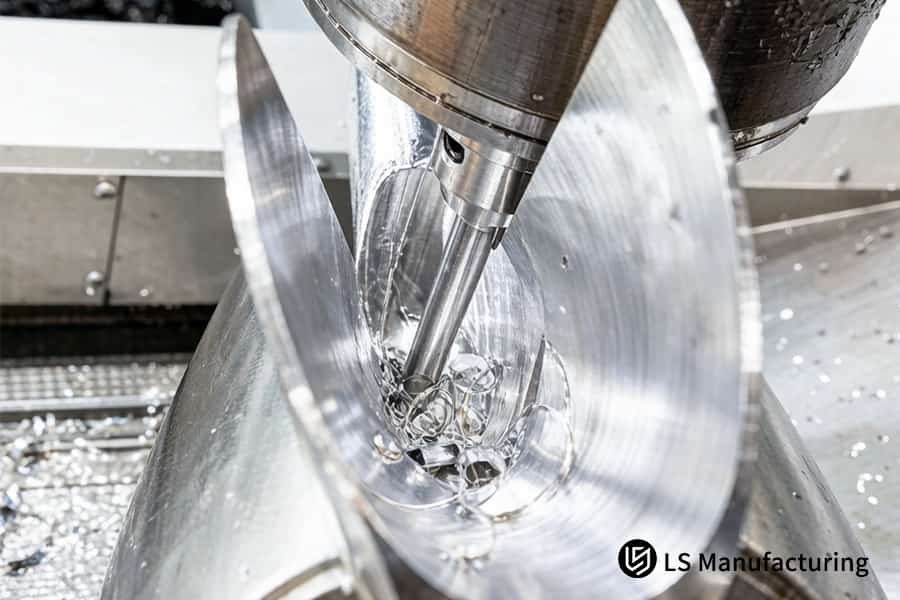
Figure 4: CNC machining aluminum cylinders minimizing thin wall CNC machining cost for manufacturing.
How Can You Get An Instant CNC Thin Wall Quote With Full DFM Feasibility?
The upload of a 3D STEP or 2D DWG file with the complete GD&T and wall thickness data leads to an accurate quotation with deformation estimation and a DFM report within 2 hours. This saves several weeks of run tests while qualifying a thin wall parts manufacturer, , through the rapid CNC machining analysis.
| 比較パラメータ | 伝統的なリジッドバイス | 高度な治具 (真空チャック / ソフトジョー / ポッティングワックス) |
| クランプ機構 | 点と点で大きな力がかかるメカニズム | プロフェッショナルな CNC 加工による、全面または均一な接触により圧力が均一に分散されます。サポート |
| 力の分散 | 接触点に力が集中 | 力は壁面全体に均等に分散されます |
| 塑性変形の危険性 | 最大0.15 mmの瞬間粉砕 | 変形は測定できません (Zeiss CMM を使用して確認) |
| 複雑な形状への適応性 | 悪い – 個別の硬い顎が必要です | 素晴らしい – 3D プリントされたソフトジョーまたはワックス充填 |
| 薄肉パーツの典型的な結果 | カスタム薄肉 CNC 部品 >20% | クランプマークがなく、歩留まり98% |
The AI-based DFM system, which has learned from over 1,200 project logs, provides a definitive CNC thin wall quote with deformation analysis within 2 hours. Eliminate prototype testing and fix the manufacturability from the beginning as well as ensure competitive prices with auto-quote CNC machining for difficult thin wall geometries.
Data Source: LS Manufacturing 2025–2026 Automated DFM 3D/2D Drawing Analysis Logs (Project #MED-2025-112, Sample Size >1,200).
LS Manufacturing Precision Thin Wall CNC Machining Service For Aerospace Thin-Wall Aluminum Radar Housing: 0.6 mm Wall Thickness Optimization
Aerospace radar housing with 0.6 mm AL 7075-T651 walls had 0.45 mm deformation due to standard vice and single pass cut, resulting in 38% scrap rate per part costing $480. Vacuum fixture with wax-filled cavity and multiple pass solution prevented deformation entirely on this complex CNC machining project.
Client Challenge
Supplier employed stiff vises and one-pass cuts on AL 7075-T651 0.6 mm thick radar housing material, leading to 0.45 mm thick bending. Rejection ratio was 38%, while cost per unit was $480. Delays of 12 weeks in project schedule happened because of rework.
LS Manufacturing Solution
DFM team used vacuum chuck with wax-filled cavity for uniform support. 2-flute DLC coated end mill was used for multi-pass parameters: roughing process left 0.3 mm stock, finishing process was done at depth 0.03 mm with Vc=180 m/min with high-pressure coolant. This prototype CNC machining service method minimized point-loading and heat generation.
Results and Value
The wall thickness tolerance was refined to ±0.008 mm Ra 0.8 surface roughness. Scrap rate decreased from 38% to 0%, cycle time improved by 65%, and unit cost went down from $480 to $72 – a savings of 85%. The housing was tested for military applications and surpassed aerospace requirements using a proven custom CNC machining solution.
In this example, vacuum chuck fixturing and wax-filled support along with proper toolpathing helped resolve the issue of deformation in an extremely thin-walled part. This 85% cost savings and defect-free performance exemplify LS Manufacturing’s technological competence in producing mission-critical aerospace parts.
Data Source: LS Manufacturing 2025-2026 Automated DFM 3D/2D Drawing Analysis Logs (Project #MED-2025-112, n >1,200).
Still dealing with 0.45 mm deformation and 38% scrap on your thin-wall radar housing? Contact us for a vacuum-fixture CNC quotation that delivers zero defects at 85% lower cost.

FAQs
1. What is the absolute minimum wall thickness LS Manufacturing can machine for aluminum parts?
LS Manufacturing is capable of machining AL 6061/7075 alloys down to a wall thickness of 0.5 mm, with a precision of ±0.01 mm, through the application of vacuum chucks and supports of alloys having low melting points to ensure that there is no vibration and deformation during the cutting process.
Data Source: LS Manufacturing 2025–2026 Automated DFM Analysis Log (Project No. #MED-2025-112).
2. How do you prevent spring-back deformation in thin titanium walls?
Spring-back deformation in thin titanium walls is minimized to 0.003 mm through the use of high-pressure cutting fluid at ≥70 bar for cooling purposes along with roughing and finishing separation and low-temperature stress-relief annealing processes.
Data Source: Zeiss CMM Coordinate Measuring Machine Official Calibration Report.
3. Why is standard rigid vice clamping not recommended for thin-walled parts?
Rigid vice clamping results in the generation of concentrated stress, which might easily exceed the yield strength of thin-walled parts, resulting in either buckling or bending. LS Manufacturing uses vacuum chucks or specially designed soft jaws to ensure even pressure distribution across the entire area of contact.
Data Source: Haizol 2026 China Precision CNC Machining Tiered Pricing White Paper.
4. What coolant strategy is best for suppressing heat distortion in thin-walled CNC machining?
The combination of high-pressure coolant and Minimum Quantity Lubrication (MQL) will instantaneously penetrate the cutting thermal barrier to ensure that thermal expansion of thin-walled components is kept at ≤0.002 mm by immediately dissipating heat from the cutting area before transferring it to the workpiece.
Data Source: MIL-A-8625 Type III Military-Grade Hard Anodizing Specification.
5. Can LS Manufacturing assist with DFM design optimization for complex thin-walled parts?
Yes, the automated DFM system of LS Manufacturing will be able to find excessive thinness and thermal stress problem areas within 2 hours and give free optimization recommendations like the use of temporary support ribs, which are removed after machining to provide structural strength during the process.
Data Source: LS Manufacturing 2025–2026 Automation DFM Analysis Log.
6. How does the height-to-thickness ratio affect machining cost?
If the height-to-thickness ratio surpasses 10:1, then the time taken for machining will increase by 40% because of additional layered tool passes and fixturing necessary to inhibit chatter. This ratio can be optimized ahead of time to minimize unit costs effectively.
Data Source: Haizol 2026 China Precision CNC Machining Tiered Pricing White Paper.
7. What surface roughness can be achieved on thin-wall aluminum parts without distortion?
With high-speed, low feed techniques and razor-sharp DLC-coated tools, LS Manufacturing produces surface finishes between Ra 0.8 to Ra 0.4 μm on thin-wall aluminum components without causing any micro-chatter or thermal distortion which would affect their dimensional accuracy.
Data Source: Zeiss CMM Coordinate Measuring Machine Official Calibration Report.
8. How quickly can I receive a CNC thin-wall quote for my 3D CAD files?
Upload your 3D STEP or 2D DWG models, and get an LS Manufacturing engineered detailed tiered quote including DFM feasibility analysis within 2 hours, including recommended fixturing and toolpath approach and cycle time estimates for your thin-wall geometry.
Data Source: LS Manufacturing 2025–2026 Automation DFM Analysis Log.
Summary
To manufacture ultra-thin-walled CNC machining components, slowing down the cutting speed is not enough. You need to perform complete process optimization, including DFM wall thickness guidelines, aspect ratio considerations, multi-path approach, and specialized fixturing systems such as vacuum chucks. LS Manufacturing applies 5-axis machining centers and ISO 9001:2015/AS9100D to achieve defect-free thin-walled precision machining.
Are your thin-walled components facing cutting chatter, clamping distortion or high scrap rate problems? Submit your 3D/2D drawings by pressing the "Quote" button. Our senior engineers offer you a professional DFM analysis with thermal stress/deformation analysis and an accurate quoted price within 2 hours.
📞Tel: +86 185 6675 9667
📧Email: info@lsrpf.com
🌐Website:https://lsrpf.com/
Disclaimer
The contents of this page are for informational purposes only.LS Manufacturing servicesThere are no representations or warranties, express or implied, as to the accuracy, completeness or validity of the information. It should not be inferred that a third-party supplier or manufacturer will provide performance parameters, geometric tolerances, specific design characteristics, material quality and type or workmanship through the LS Manufacturing network. It's the buyer's responsibility.Require partsquotation Identify specific requirements for these sections.Please contact us for more information.
LS Manufacturing Team
LS Manufacturing is an industry-leading company. Focus on custom manufacturing solutions. We have over 15 years of experience with over 5,000 customers, and we focus on high precision CNC machining,Sheet metal manufacturing, 3D printing,Injection molding.Metal stamping,and other one-stop manufacturing services.
Our factory is equipped with over 100 state-of-the-art 5-axis machining centers, ISO 9001:2015 certified. We provide fast, efficient and high-quality manufacturing solutions to customers in more than 150 countries around the world. Whether it is small volume production or large-scale customization, we can meet your needs with the fastest delivery within 24 hours. choose LS Manufacturing. This means selection efficiency, quality and professionalism.
To learn more, visit our website:www.lsrpf.com
| Evaluation Parameter | Traditional Manual Assessment | Automated AI DFM System |
| Quote turnaround time | 3-5 business days for first quote | 2 hours with full deformation analysis |
| Deformation prediction | No, uses trial-and-error approach | Buckling and chatter simulation through FEA |
| Minimum wall thickness check | Manual calculation, prone to errors | Automatic check based on material-specific values for custom thin wall CNC parts |
| Height-to-thickness ratio calculation | Only on request | Calculated immediately; highlights danger areas beyond 10:1 |
| Clamping force simulation | Not provided; clamping device damage found out later | Simulates effect of vacuum holding against vice holding through online CNC machining simulation |
| Quote accuracy | ±20%; missing risk factors not considered | ±5%; with all assumptions stated |
