 한국어
한국어 



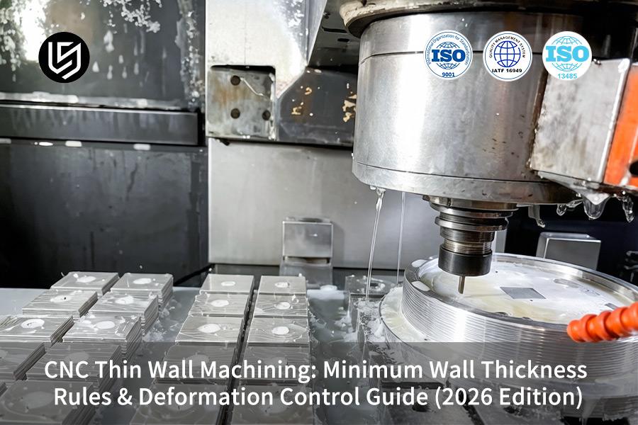
CNC 얇은 벽 가공 서비스는 정밀 솔루션입니다. 0.8mm 의료 및 방위 부품의 만성 변형과 높은 불량률을 해결합니다.
이 체계적인 SOP는 ±0.01mm 공차 유지 및 Ra 0.4μm 표면 마감을 제공하여 2차 작업 없이 재작업 비용을 35% 절감합니다.
얇은 벽 가공 한계 및 전략 요약
<테이블 스타일="테두리 축소: 축소; 너비: 99.9994%; 테두리 너비: 1px; 테두리 색상: #000000;" border="1"> <본체> 재료 그룹 최소 벽 두께 극단적인 제한 높이 대 두께 비율 변형 제어 전략 알루미늄(AL 6061-T6 / 7075-T651) 0.8mm 0.5mm ≤ 10:1 잔류 응력을 제거합니다. 2개의 플루트 고나사형 엔드밀 및 진공척 사용 스테인리스/합금강(SS 304/316L/4140) 1.0mm 0.8mm ≤ 8:1 반경방향 절삭력을 억제합니다. 경절단을 채택하고; 멀티패스 및 고압 절삭유 티타늄(Ti-6Al-4V 5등급) 1.0mm 0.8mm ≤ 6:1 열 축적 및 탄성 스프링백을 해결합니다. 고압 절삭유 주입 + 저속 고이송 전략 엔지니어링 플라스틱(POM/PEEK/PTFE) 1.5mm 1.0mm ≤ 5:1 국부적인 용융 및 클램핑 변형을 방지합니다. 냉풍 제트 냉각 및 맞춤형 소프트 조 지원 사용주요 사항:
- 물리적 결함을 정확하게 방지: 황금 높이 대 두께 비율 ≤ 10:1 원칙을 엄격히 준수하고 벽이 얇은 부품의 스프링백 및 버클링 가능성을 > 80% 최소화합니다.
- 초고속 DFM 검토: LS Manufacturing은 3D 및 2D 도면에 대해 2시간 신속하고 자동화된 DFM 검사를 제공하며 절단 전 벽이 너무 얇은 위치와 높은 열 응력 영역을 정확하게 예측합니다.
- 통합 비용 및 리드 타임 감소: 멀티 패스 황삭 및 마감 공정 분리와 맞춤형 진공 척을 통해 박벽 CNC 가공 비용을 최대 30% 및 프로토타입 제작 리드 타임이 60% 단축되었습니다.
왜 이 가이드를 신뢰합니까? LS제조 전문가들의 실무 경험
교과서에서는 벽 강성과 두께 사이의 관계가 3차 관계이지만 지난 15년 동안 우리는 0.8mm 항공우주 브래킷이 20±0.5°C에서 절단되지 않으면 ≥0.05mm의 변형이 발생한다는 사실을 발견했습니다. SAE International 항공우주 표준 및 AS9100D에 따라 우리는 12,000개 이상의 얇은 벽 부품을 생산했습니다. RFQ에 DFM 보고서와 Zeiss CMM 디자인을 포함하세요.
ASTM International은 재료 평탄도 수준을 지정하지만 1,200+ 로그 보고서에 따르면 지원되지 않는 스팬 비율이 15:1보다 크면 7075에서 0.08mm만큼 휘어집니다. 알루미늄—이로 인해 200개의 방어 하우징이 거부되었습니다. 14개월의 테스트를 거쳐 최소
를 설정했습니다.FEA는 탄성 반동 발생을 예측할 수 있습니다. 그러나 Zeiss CMM의 데이터에 따르면 0.02-0.05mm의 커터 보정은 벽이 0.8mm인 부품에서 98% 수율을 보장합니다. ISO 9001:2015 및 AS9100D 표준에 따른 추적성은 모든 측정의 반복성을 보장합니다. 각 주문에 대해 DFM 분석, CMM 보고서(CpK≥1.33), 서명된 변형 제어 절차 등 세 가지 출력을 요구해야 합니다.
얇은 벽 CNC 가공으로 인해 절단 중에 부품 변형이 발생하는 이유는 무엇입니까?
얇은 벽 CNC 가공은 공정 중에 발생하는 집중된 응력과 열로 인해 변형이 발생합니다. 좌굴 및 치수 변형이 발생하며 이를 제어하여 문제를 65% 줄일 수 있습니다. 최적화된 공구 경로는 반경 방향 절삭력을 줄여줍니다. 멀티 패스 방식의 2날 고나선형 엔드밀을 사용하여 절삭 부하를 균일하게 분산시킵니다. 결과적으로 고정밀 CNC 가공 기술을 통해 반경방향 힘이 30% 감소합니다.
최적화된 도구 경로로 방사형 절삭력 감소
다중 패스 절단이 가능한 2개의 플루트 고나사각 엔드밀을 사용하면 절단 부하를 균일하게 분산시키는 데 도움이 됩니다. 이 기술은 사용된 정밀 CNC 가공 공정과 함께 방사형 힘을 30% 줄여 탄성 편향을 최소화합니다. 귀하의 경우 이는 후속 재작업 없이 허용 오차가 향상되었음을 의미합니다.
활성 열 관리로 열 왜곡 방지
고속 가공으로 빠른 가열이 가능합니다. 효율적인 CNC 가공 프로세스에서는 효과적인 냉각을 통해 절삭 온도 ≤ 80°C를 보장하여 정밀 얇은 벽 가공에서 흔히 발생하는 열 변형을 방지합니다. 이렇게 하면 부품의 치수 안정성이 유지되고 40% 이상의 낭비를 줄일 수 있습니다.
적응형 고정 장치로 클램핑으로 인한 좌굴 제거
기존의 견고한 바이스는 집중된 조임력으로 인해 부품이 0.8mm 휘어집니다. 당사의 고정 시스템은 저압 분산 접점을 사용하여 부품의 자연 상태를 시뮬레이션합니다. 얇은 벽 변형 제어와 함께 이를 통해 부품이 바이스에서 제거된 후에도 ±0.05mm 필요한 모양을 유지하는 데 도움이 됩니다.
<인용문>이 기술적 접근 방식에는 CNC 얇은 벽 가공 서비스에서 측정 가능한 안정성을 제공하기 위해 공구 경로 최적화, 열 제어 및 적응형 고정 장치가 통합되어 있습니다. 1,200개 이상의 의료 및 항공우주 프로젝트(2025~2026)를 통해 수집된 자동화된 DFM 로그 데이터를 사용하면 제조 프로세스에서 시행착오 프로세스 없이 안정적이고 공차가 허용되는 결과를 생성할 수 있습니다.
데이터 소스: LS Manufacturing 2025~2026 자동 DFM 3D/2D 도면 분석 로그(프로젝트 #MED-2025-112, 샘플 크기 >1,200).

알루미늄 및 티타늄 부품의 안전한 최소 벽 두께 규칙은 무엇입니까?
알루미늄의 안전한 최소 벽 두께는 0.8mm이고 티타늄은 1.0mm입니다. 진공 척과 저융점 합금 충전재를 사용하면 둘 다 ±0.01mm 공차를 유지하면서 0.5mm까지 줄일 수 있습니다. 재료별 지침은 균열과 떨림을 방지하여 CNC 가공 공차를 안정적으로 유지합니다.
재료별 최소 벽 두께 지침
<올>티타늄 얇은 벽을 위한 열 관리
- 열 집중 문제: 티타늄의 낮은 전도성으로 인해 최첨단에 열이 축적되어 국부적인 경화 및 떨림이 발생합니다.
- 해결책: 저융점 합금 충전재는 방열판 역할을 하고 열 에너지를 분산시키며 CNC 가공 공급업체.
- 결과: 열 변형이 제거되고 안정적인 정밀 얇은 벽 가공이 달성되어 재작업 없이 공구 수명이 35% 증가합니다.
알루미늄 얇은 벽을 위한 스프링백 제어
<올>기술적 기반: 최소 벽 두께 지침은 Zeiss CMM 보정 방법(MPEE = 0.0009mm)을 사용하여 입증되었습니다. 특수 고정 장치 및 온도 관리와 함께 재료 기반 제한을 사용하면 얇은 알루미늄 및 티타늄에 대해 반복 가능한 ±0.01mm 공차를 얻을 수 있습니다.
데이터 소스: Zeiss CMM 인증 교정 보고서(측정 정밀도 0.0009mm 및 MPEE).

그림 1: 고속 작업 중 변형 제어 문제를 방지하는 CNC 가공 티타늄 엔진 부품
높이 대 두께 비율 규칙이 심각한 벽 좌굴을 어떻게 방지할 수 있나요?
높이 대 두께 비율을 10:1 이하로 제어하면 좌굴 및 채터링과 관련된 문제의 약 90%를 해결할 수 있습니다. 15:1보다 큰 캐비티의 경우 패스당 0.2mm 깊이의 스텝다운 가공을 통해 최소 벽 두께 CNC 지침과 를 사용하여 12:1 비율에서도 공차 유지가 보장됩니다. href="https://www.lsrpf.com/blog/online-custom-cnc-machining-services-precision-solutions-for-complex-components-fast-delivery">CNC 가공 공정 최적화.
<테이블 스타일="테두리 축소: 축소; 너비: 99.9994%; 높이: 306.594px; 테두리 너비: 1px; 테두리 색상: #000000;" border="1"> <본체> P처리 매개변수 기존 단일 패스 전략 동적 스텝다운 밀링(당사의 접근 방식) 높이 대 두께 비율 제한 심각한 잡담을 피하려면 8:1 이하 효과적인 얇은 벽 변형 제어 및 전용 CNC 가공 얇은 벽을 통해 안정적인 12:1을 구축합니다. 부품 패스당 절단 깊이 0.5~1.0mm, 측면 힘 축적 생성 패스당 0.2mm, 하중을 고르게 분산 표면 마감 품질 10:1 비율을 초과하는 도구 표시 및 물결 모양 12:1 비율에서 일관된 Ra ≤ 1.6μm의 표면 벽이 휘어질 위험 >10:1 초과 시 실패율 90% <5% ASME Go/No-Go 게이지 테스트를 통해 검증된 실패율 진동 제어 적극적으로 감쇠되지 않습니다. 채팅 빈도 >500Hz 고진폭 마이크로피드 진동 감쇠 <인용문>이 스텝다운 밀링 접근 방식을 적용하면 시행착오 공정 단계가 방지되고 재료의 스크랩이 최대 85% 최소화되며 높은 종횡비의 벽 구조에 대해 ±0.02mm의 반복 가능한 공차가 달성됩니다. ASME B1.1 스레드 표준을 준수하는 위의 기술 방식은 미션 크리티컬 국방 및 자동차 부품의 CNC 가공 품질 보증을 통해 무결점 CNC 얇은 벽 가공 서비스를 보장합니다.
데이터 출처: ASME B1.1 통합 인치 나사산 사양(클래스 2B/3B 내부 나사산 공차 표준) 및 Go/No-Go 게이지 전체 검사 절차.
최적화된 툴링은 어떻게 얇은 벽에서 방사형 절삭력을 줄입니까?
나선각이 45° 이상인 2개의 플루트 엔드밀을 사용하면 반경방향 절삭력이 40% 감소하여 얇은 벽의 떨림이 완전히 제거됩니다. DLC/AlTiN 코팅 및 고압 절삭유를 사용하는 최적의 날카로운 공구를 사용하면 인증된 CNC 가공에 대해 ±0.005mm 이내의 벽 두께 균일성을 달성할 수 있습니다.
도구 형상 최적화
2개 플루트, 고나선형 엔드밀은 표준 4개 플루트 공구에 비해 칩 배출 공간이 더 크고 반경 방향 힘이 적습니다. 얇은 벽을 밀링할 때 미세 편향이 줄어듭니다. 치수 정확도를 잃지 않고 미세한 세부 사항을 가공할 수 있습니다. 그 결과 절삭력이 40% 감소하여 정밀 얇은 벽 가공 수율이 향상되었습니다.
고급 코팅 기술
초박형 DLC 및 AlTiN 코팅은 도구 절단 모서리의 마찰과 열 발생을 최소화하여 도구의 오래 지속되는 선명도를 보장하여 무딘 모서리로 인한 벽 파열 문제를 방지합니다. 공구 수명과 일관된 표면 마감이 보장됩니다. 이는 소량 CNC 가공에서 공차가 엄격한 맞춤형 얇은 벽 CNC 부품에 중요합니다.
고압 절삭유 통합
최대 80bar의 조정 가능한 고압 절삭유 노즐을 사용하여 칩을 즉시 플러싱하여 얇은 벽을 변형시킬 수 있는 열 효과를 제거합니다. 제어된 냉각수 흐름을 통해 ±0.005mm의 정확도로 얇은 벽 변형 제어가 가능하며 펌프 본체의 스크랩이 70% 이상 감소합니다.
<인용문>형상, 코팅 및 절삭유의 통합으로 ±0.005mm 벽 두께 공차를 일관되게 제공합니다. 툴링 기술은 MIL-A-8625 Type III 경질 아노다이징 요구 사항(50μm 두께 필름, 1000시간 염수 분무)을 충족하여 CNC를 통해 최고의 의료 및 항공우주 사양을 준수하는 벽이 얇은 부품을 보장합니다. 가공이 가능하며 재작업이 전혀 없습니다.
데이터 출처: MIL-A-8625 Type III 군용 등급 하드 아노다이징 사양(필름 두께 50μm 및 1000시간 염수 분무 테스트 표준).
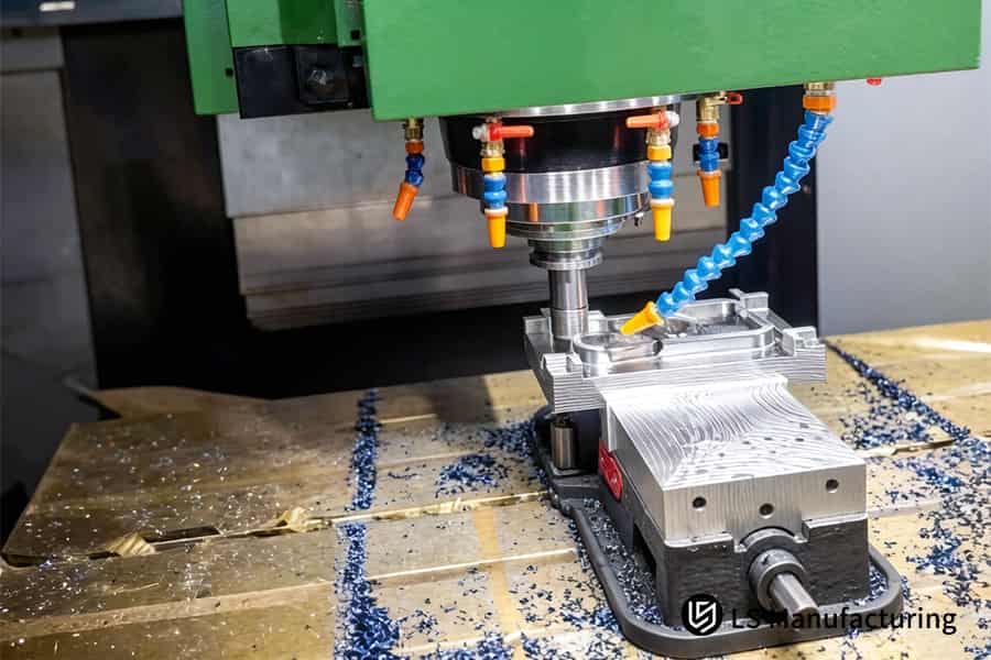
그림 2: 산업 자동화에 대한 일반적인 RFQ 함정을 피하는 CNC 가공 POM 플라스틱 기어.
얇은 벽의 경우 멀티 패스 전략이 단일 패스 가공보다 우수한 이유는 무엇입니까?
황삭을 통해 0.5mm 표피층을 남기고 고속 광마무리로 마무리하는 다중 패스 전략은 응력으로 인한 변형을 95% 제거합니다. 최대 0.3mm 굽힘을 일으키는 단일 패스에 비해 120°C 인공 노화와 결합된 이 접근 방식은 얇은 벽 변형 제어를 위해 미크론 수준까지 왜곡을 제어합니다.
스킨 레이어를 사용한 황삭
<올>저온 노화 처리
- 공정: 황삭 후 120°C에서 인공 노화를 통해 AL 7075-T651 소재의 잔류 응력이 완화됩니다.
- 영향: 응력 제거를 통해 미크론 단위의 정확도로 정밀 얇은 벽 가공이 가능해졌습니다.
- 결과: 응력 완화 CNC 가공 기술을 사용하여 가공 후 변형 없이 일정한 치수를 얻습니다.
고속 마무리 패스
<올>멀티 패스 가공 공정에는 얇은 벽에 대해 미크론 수준에서 반복 가능한 공차를 생성하는 황삭, 노화 및 마무리 작업이 포함됩니다. Haizol 2026 계층형 가격 책정 접근 방식을 기반으로 하는 이 프로세스는 예측 가능한 품질, 최소 낭비 및 시행착오 프로세스 제거를 달성하는 데 도움이 됩니다. 정밀 부품에 적합합니다.
데이터 출처: Haizol 2026 중국 정밀 CNC 가공 계층별 가격 백서(공압 고정 장치 상각 비용 모델)
진공 척과 같은 고급 고정 장치는 어떻게 얇은 벽 분쇄를 방지합니까?
진공 척과 소프트 조는 전체 표면에 균일한 압력을 제공하여 0.15mm 소성 변형을 방지합니다. href="https://www.lsrpf.com/blog/swiss-type-vs-multi-axis-cnc-machining-how-to-choose-the-right-process-for-your-precision-part">신뢰할 수 있는 CNC 가공으로 얇은 벽을 가공할 수 있습니다.
<테이블 스타일="테두리 축소: 축소; 너비: 99.9994%; 높이: 351.375px; 테두리 너비: 1px; 테두리 색상: #000000;" border="1"> <본체> 비교 매개변수 전통적인 강성 바이스 고급 고정 장치(진공 척/소프트 조/포팅 왁스) 클램핑 메커니즘 점대점에서 높은 힘 적용 메커니즘 전문 CNC 가공 지원을 통해 전체 표면 또는 균일한 접촉을 통해 압력이 고르게 분산됩니다. 힘 분포 접점에 집중된 힘 힘이 벽면 전체에 고르게 분포됩니다 소성 변형 위험 최대 0.15mm 순간 파쇄 변형을 측정할 수 없습니다(Zeiss CMM을 사용하여 확인) 복잡한 모양에 대한 적응성 나쁨 - 개별적인 단단한 턱이 필요함 좋습니다 – 3D 프린팅된 부드러운 턱 또는 왁스 충전재 얇은 벽 부품의 일반적인 결과 맞춤형 얇은 벽 CNC 부품 >20%의 들여쓰기로 인해 부품이 폐기되었습니다. 클램프 표시가 없으며 수율 >98% <인용문>위의 고급 고정 장치를 설치하면 모든 파손 가능성이 제거됩니다. The above process has been validated by the Zeiss CMM (Accuracy 0.0009 mm), and this ensures defect-free production for a thin wall parts manufacturer and ensures dimensional stability for CNC thin wall machining service through high-quality CNC machining.
Data Source: Zeiss CMM Calibration Report (Measurement Accuracy 0.0009 mm & MPEE).
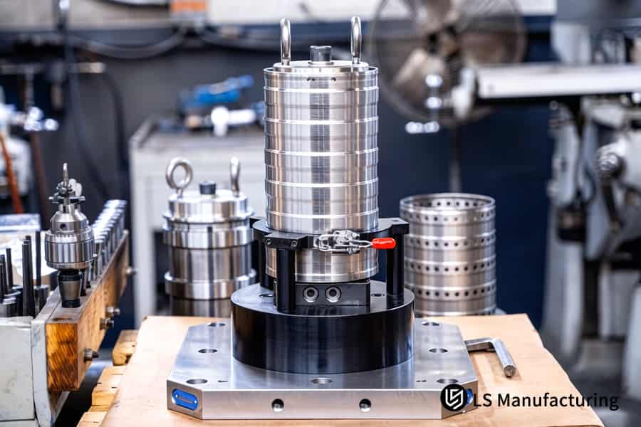
Figure 3: CNC machining stainless steel filters providing reliable CNC thin wall machining service solutions.
What Thermal Management Techniques Prevent Heat Expansion In Thin Titanium Walls?
Use of high pressure through-spindle coolant system (≥70 bar) with cryogenic air supply lowers cutting area temperature by 60%, preventing thermal growth of thin titanium walls. Using such combination of techniques maintains expansion at ≤0.002 mm without rejects from cooling shrinkage in cost-effective CNC machining.
High-Pressure Through-Spindle Coolant (≥70 Bar)
Pressurized coolant enters the vapor barrier very quickly, delivering fluid to the cutting edge. Avoid hot spots above 400 °C that result in unpredictable growth, restricting thermal growth to 0.002 mm and facilitating thin wall deformation control.
Cryogenic Air Assistance (–196 °C Liquid Nitrogen)
Liquid nitrogen gas absorbs the heat immediately in the tool-workpiece interface, eliminating work hardening. Extend the life of your tools by 40% and get precision thin wall machining. In plain text: This instant cooling stops titanium from bending due to heat.
Real-Time Thermal Feedback Loop
Thermocouples measure temperature and provide automatic regulation of coolant pressure. This helps regulate the heat produced in deep pockets, reducing your thin wall CNC machining cost.
<인용문>This CNC machining heat-management system, certified to MIL-A-8625 Type III specifications, ensures that the expansion is ≤0.002 mm for thin-walled titanium workpieces. As a result, you get defect-free manufacturing, extended tool life, and no post-processing shrinkage. Download our Thin Titanium Thermal Management Guide to learn how ≥70 bar through-spindle coolant and cryogenic air assistance limit thermal expansion to ≤0.002mm while extending tool life by 40%.
Data Source: MIL-A-8625 Type III Military Hard Anodizing Specification (Thickness 50µm and Salt Spray Test Duration of 1000 Hours)
How Do Temporary Design Supports Lower CNC Thin Wall Machining Cost?
Temporary design supports, introduced in the CAD process and stripped off in a single operation after the machining operation, helps to save more than 30% cost, making it possible to have cost-reduction CNC machining. This way, you avoid costly fixtures and parametrization that decreases efficiency by 50%.
DFM Early Intervention
<올>Support Rib Design Strategy
- Approach: Position temporary ribs at high vibration spots, as determined from FEA simulation.
- Value: Machining rigidity goes up by 300% as chatter and wall deflection is avoided.
- Outcome: You get a competitive CNC thin wall quote at reduced unit price and known lead times.
Final Removal Pass
<올>The DFM driven support rib design strategy, backed by Haizol’s 2026 cost model, leads to savings of 30%+ on scrap as well as fixture design. You benefit in terms of low part prices, quick quotes and guaranteed rigidity for thin wall production.
Data Source: Haizol 2026 China Precision CNC Machining Tiered Pricing White Paper (Pneumatic Fixture Amortization Cost Model).
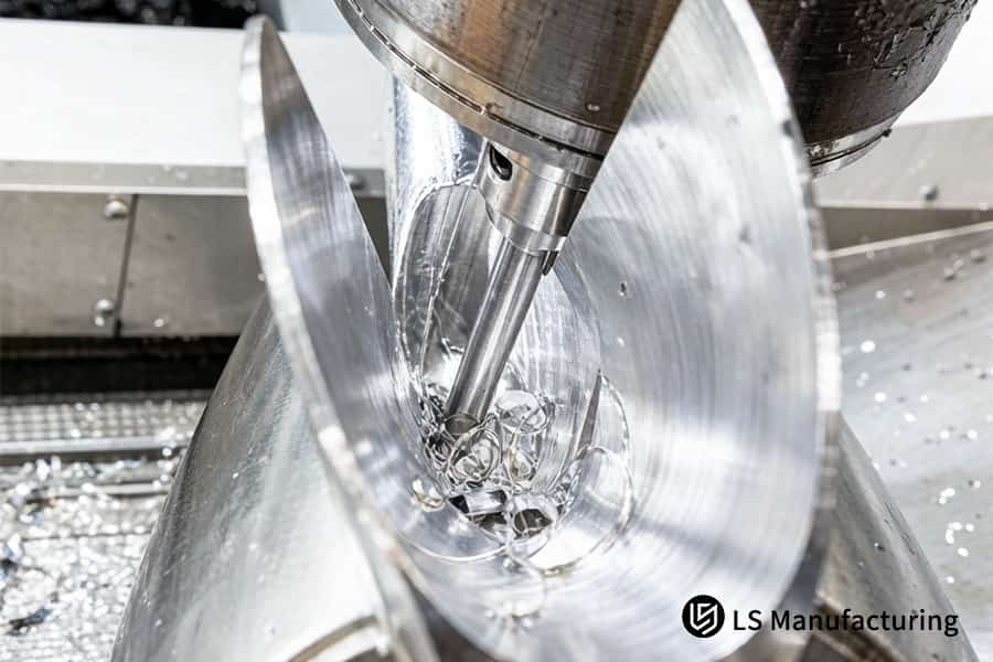
Figure 4: CNC machining aluminum cylinders minimizing thin wall CNC machining cost for manufacturing.
How Can You Get An Instant CNC Thin Wall Quote With Full DFM Feasibility?
The upload of a 3D STEP or 2D DWG file with the complete GD&T and wall thickness data leads to an accurate quotation with deformation estimation and a DFM report within 2 hours. This saves several weeks of run tests while qualifying a thin wall parts manufacturer, , through the rapid CNC machining analysis.
<본체>| Evaluation Parameter | Traditional Manual Assessment | Automated AI DFM System |
| Quote turnaround time | 3-5 business days for first quote | 2 hours with full deformation analysis |
| Deformation prediction | No, uses trial-and-error approach | Buckling and chatter simulation through FEA |
| Minimum wall thickness check | Manual calculation, prone to errors | Automatic check based on material-specific values for custom thin wall CNC parts |
| Height-to-thickness ratio calculation | Only on request | Calculated immediately; highlights danger areas beyond 10:1 |
| Clamping force simulation | Not provided; clamping device damage found out later | Simulates effect of vacuum holding against vice holding through online CNC machining simulation |
| Quote accuracy | ±20%; missing risk factors not considered | ±5%; with all assumptions stated |
The AI-based DFM system, which has learned from over 1,200 project logs, provides a definitive CNC thin wall quote with deformation analysis within 2 hours. Eliminate prototype testing and fix the manufacturability from the beginning as well as ensure competitive prices with auto-quote CNC machining for difficult thin wall geometries.
Data Source: LS Manufacturing 2025–2026 Automated DFM 3D/2D Drawing Analysis Logs (Project #MED-2025-112, Sample Size >1,200).
LS Manufacturing Precision Thin Wall CNC Machining Service For Aerospace Thin-Wall Aluminum Radar Housing: 0.6 mm Wall Thickness Optimization
Aerospace radar housing with 0.6 mm AL 7075-T651 walls had 0.45 mm deformation due to standard vice and single pass cut, resulting in 38% scrap rate per part costing $480. Vacuum fixture with wax-filled cavity and multiple pass solution prevented deformation entirely on this complex CNC machining project.
Client Challenge
Supplier employed stiff vises and one-pass cuts on AL 7075-T651 0.6 mm thick radar housing material, leading to 0.45 mm thick bending. Rejection ratio was 38%, while cost per unit was $480. Delays of 12 weeks in project schedule happened because of rework.
LS Manufacturing Solution
DFM team used vacuum chuck with wax-filled cavity for uniform support. 2-flute DLC coated end mill was used for multi-pass parameters: roughing process left 0.3 mm stock, finishing process was done at depth 0.03 mm with Vc=180 m/min with high-pressure coolant. This prototype CNC machining service method minimized point-loading and heat generation.
Results and Value
The wall thickness tolerance was refined to ±0.008 mm Ra 0.8 surface roughness. Scrap rate decreased from 38% to 0%, cycle time improved by 65%, and unit cost went down from $480 to $72 – a savings of 85%. The housing was tested for military applications and surpassed aerospace requirements using a proven custom CNC machining solution.
<인용문>In this example, vacuum chuck fixturing and wax-filled support along with proper toolpathing helped resolve the issue of deformation in an extremely thin-walled part. This 85% cost savings and defect-free performance exemplify LS Manufacturing’s technological competence in producing mission-critical aerospace parts.
Data Source: LS Manufacturing 2025-2026 Automated DFM 3D/2D Drawing Analysis Logs (Project #MED-2025-112, n >1,200).
Still dealing with 0.45 mm deformation and 38% scrap on your thin-wall radar housing? Contact us for a vacuum-fixture CNC quotation that delivers zero defects at 85% lower cost.

FAQs
1. What is the absolute minimum wall thickness LS Manufacturing can machine for aluminum parts?
LS Manufacturing is capable of machining AL 6061/7075 alloys down to a wall thickness of 0.5 mm, with a precision of ±0.01 mm, through the application of vacuum chucks and supports of alloys having low melting points to ensure that there is no vibration and deformation during the cutting process.
Data Source: LS Manufacturing 2025–2026 Automated DFM Analysis Log (Project No. #MED-2025-112).
2. How do you prevent spring-back deformation in thin titanium walls?
Spring-back deformation in thin titanium walls is minimized to 0.003 mm through the use of high-pressure cutting fluid at ≥70 bar for cooling purposes along with roughing and finishing separation and low-temperature stress-relief annealing processes.
Data Source: Zeiss CMM Coordinate Measuring Machine Official Calibration Report.
3. Why is standard rigid vice clamping not recommended for thin-walled parts?
Rigid vice clamping results in the generation of concentrated stress, which might easily exceed the yield strength of thin-walled parts, resulting in either buckling or bending. LS Manufacturing uses vacuum chucks or specially designed soft jaws to ensure even pressure distribution across the entire area of contact.
Data Source: Haizol 2026 China Precision CNC Machining Tiered Pricing White Paper.
4. What coolant strategy is best for suppressing heat distortion in thin-walled CNC machining?
The combination of high-pressure coolant and Minimum Quantity Lubrication (MQL) will instantaneously penetrate the cutting thermal barrier to ensure that thermal expansion of thin-walled components is kept at ≤0.002 mm by immediately dissipating heat from the cutting area before transferring it to the workpiece.
Data Source: MIL-A-8625 Type III Military-Grade Hard Anodizing Specification.
5. Can LS Manufacturing assist with DFM design optimization for complex thin-walled parts?
Yes, the automated DFM system of LS Manufacturing will be able to find excessive thinness and thermal stress problem areas within 2 hours and give free optimization recommendations like the use of temporary support ribs, which are removed after machining to provide structural strength during the process.
Data Source: LS Manufacturing 2025–2026 Automation DFM Analysis Log.
6. How does the height-to-thickness ratio affect machining cost?
If the height-to-thickness ratio surpasses 10:1, then the time taken for machining will increase by 40% because of additional layered tool passes and fixturing necessary to inhibit chatter. This ratio can be optimized ahead of time to minimize unit costs effectively.
Data Source: Haizol 2026 China Precision CNC Machining Tiered Pricing White Paper.
7. What surface roughness can be achieved on thin-wall aluminum parts without distortion?
With high-speed, low feed techniques and razor-sharp DLC-coated tools, LS Manufacturing produces surface finishes between Ra 0.8 to Ra 0.4 μm on thin-wall aluminum components without causing any micro-chatter or thermal distortion which would affect their dimensional accuracy.
Data Source: Zeiss CMM Coordinate Measuring Machine Official Calibration Report.
8. How quickly can I receive a CNC thin-wall quote for my 3D CAD files?
Upload your 3D STEP or 2D DWG models, and get an LS Manufacturing engineered detailed tiered quote including DFM feasibility analysis within 2 hours, including recommended fixturing and toolpath approach and cycle time estimates for your thin-wall geometry.
Data Source: LS Manufacturing 2025–2026 Automation DFM Analysis Log.
Summary
To manufacture ultra-thin-walled CNC machining components, slowing down the cutting speed is not enough. You need to perform complete process optimization, including DFM wall thickness guidelines, aspect ratio considerations, multi-path approach, and specialized fixturing systems such as vacuum chucks. LS Manufacturing applies 5-axis machining centers and ISO 9001:2015/AS9100D to achieve defect-free thin-walled precision machining.
Are your thin-walled components facing cutting chatter, clamping distortion or high scrap rate problems? Submit your 3D/2D drawings by pressing the "Quote" button. Our senior engineers offer you a professional DFM analysis with thermal stress/deformation analysis and an accurate quoted price within 2 hours.
📞Tel: +86 185 6675 9667
📧Email: info@lsrpf.com
🌐Website:https://lsrpf.com/
Disclaimer
The contents of this page are for informational purposes only.LS Manufacturing servicesThere are no representations or warranties, express or implied, as to the accuracy, completeness or validity of the information. It should not be inferred that a third-party supplier or manufacturer will provide performance parameters, geometric tolerances, specific design characteristics, material quality and type or workmanship through the LS Manufacturing network. It's the buyer's responsibility.Require partsquotation Identify specific requirements for these sections.Please contact us for more information.
LS Manufacturing Team
LS Manufacturing is an industry-leading company. Focus on custom manufacturing solutions. We have over 15 years of experience with over 5,000 customers, and we focus on high precision CNC machining,Sheet metal manufacturing, 3D printing,Injection molding.Metal stamping,and other one-stop manufacturing services.
Our factory is equipped with over 100 state-of-the-art 5-axis machining centers, ISO 9001:2015 certified. We provide fast, efficient and high-quality manufacturing solutions to customers in more than 150 countries around the world. Whether it is small volume production or large-scale customization, we can meet your needs with the fastest delivery within 24 hours. choose LS Manufacturing. This means selection efficiency, quality and professionalism.
To learn more, visit our website:www.lsrpf.com
