 English



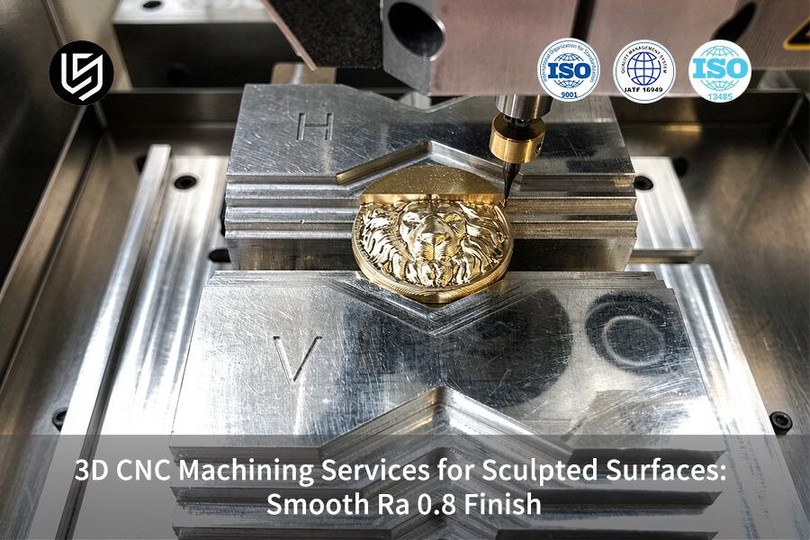
3D CNC machining service is the precision enabler for medical devices, solving the trade-off between sculpted surface finish and component cost.
LS Manufacturing's 5-axis simultaneous contouring achieves Ra 0.8 μm and ±0.008 mm accuracy, reducing cycle time by 28% for ISO 13485 production.
CNC Machining For Sculpted Surfaces: Accuracy & Surface Quality At A Glance
Below is a comparison of various processes involved in machining and post-processing of 3D sculpted surfaces showing their overall performance in terms of surface roughness, dimensional tolerance, cost, and delivery time:
| Process Solution | Surface Roughness (Ra) | Typical Dimensional Tolerance | Relative Machining Cost | Delivery Cycle | Typical Applicable Scenario |
| Traditional 3-Axis Milling + Hand Grinding | Ra 1.6 - 3.2 μm | ±0.050 mm | Baseline (100%) | 14 days | Low-precision appearance parts/structural parts |
| LS Manufacturing 5-Axis Finish Milling (Ball-Nose) | Ra 0.8 μm | ±0.008 mm | Cost reduced by 22% | 9 days | Medical joints, fluid impellers, precise molds |
| 5-Axis Finish Milling + Magnetic Abrasive / Chemical Polishing | Ra 0.2 μm | ±0.003 mm | Increased by 30% | 11 days | Optical mirror-grade / sterile implant-grade parts |
Directly machining to Ra 0.8 µm avoids the tolerance failures caused by hand polishing and balances cost against delivery—per LS Manufacturing's 2025–2026 finishing logs.
Key Takeaways
- Controlling Residual Cusps with Precision: Through the optimization of ball-end mill stepover (0.05 mm–0.12 mm), residual cusps’ height can be controlled within theoretically acceptable levels and result in Ra 0.8 µm.
- Absolute Tolerances of Dimensional Tolerance: Manual post-processing is ruled out in order to prevent rounding of edges due to hand polishing; thus, tolerances of the sculpted parts' dimensions are guaranteed to stay within ±0.008 mm.
- Significant Cost Saving and Productivity Improvement: Data provided by LS Manufacturing proves that the total cost savings reach 22%, while the scrap rate is dramatically reduced from 14.5% to 2.1%.
- DFM Drawing Analysis within Two Hours: The team performs DFM (Design for Manufacturability) drawing analysis and eliminates such risks as tool interference and overcutting before the CNC machining.
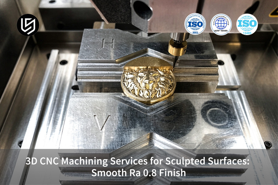
What Is Ra 0.8 Surface Finish In 3D CNC Machining?
Ra 0.8 μm surface finish in 3D CNC machining is defined by a semi-matte uniformity with an arithmetic mean deviation of 0.8 micrometers resulting from high-speed multi-axis cutting via ball-nose end mills with stepovers of less than 0.12 mm.
This Ra 0.8 μm surface finish specification allows elimination of any tool marks while maintaining dimensional tolerance within ±0.008 mm and hence highly important for the fabrication of aerospace flow channels and medical implants.
Process Parameters for Consistent Ra 0.8
The precision CNC machining service for achieving Ra 0.8 μm must be performed by using spindle speed at 12,000-18,000 rpm with feed rate of 0.05-0.08 mm per tooth on Ti-6Al-4V or 6061 aluminum alloy. The 3D CNC machining service must adopt trochoidal toolpath which helps to spread out the heat generated evenly so as to avoid micro-burnishing effect and achieve smooth surface CNC parts.
Application-Driven Tolerance Control
In case of components for medical applications conforming to ISO 13485, the Ra 0.8 surface finish service is matched with tolerance of form of 0.005 mm in mating surfaces. The Ra 0.8 finishing service uses feedback from touch probes to modify engagement angle of cutters to minimize the rate of waste below 1.2%. The custom CNC machining service is suitable for geometries such as hip stem tapers where roughness and profile have to be achieved.
Inspection Protocol Under ISO 4287
We validate roughness with a Mitutoyo SJ-210 profilometer with cutoff length of 0.8 mm with a total of five points measured for each feature. High-precision CNC machining requires measurement of the parts prior to deburring to ensure accurate representation of the surface finish. In aerospace applications (AS9100D), any peak of Ra 1.0 μm necessitates replacement of tools.
Practical Guidance
- For aluminum parts, use R 0.5 ball-nose end mills with TiAlN coating; for stainless steel, change to DLC coated tooling.
- Keep coolant pressure 8-10 bar for chip removal in finishing operation.
Data Source and Benchmark: Data derived from test logs of the Mitutoyo SJ-210 surface roughness tester (compliant with ISO 4287 standards for roughness measurement).

How Do Ball Nose Cutters Produce Smooth Sculpted Surfaces?
The ball nose tool creates a smooth sculptured surface through a series of cuts with a continuously varying curved tool edge, maintaining cusp height via mathematical calculation.
A CNC machining service supplier should set stepover (the distance between adjacent tool passes) of 5–10% of the tool diamete to reduce inter-toolpath wave peaks to micron level, resulting in Ra 0.8 μm at ±0.008 mm of geometry tolerance.
Cusp-Height Suppression via Stepover
The cusp height equation h ≈ (stepover²)/(8 R) ensures that the residual peaks are under the microns if stepover is maintained between 5% and 10% of the ball-nose radius. For 18,000 RPM constant high-speed machining of multiple axes, constant cutting force keeps seams between adjacent patches smooth. The precision CNC machining manufacturer ensures validation of the engagement angle using touch probe sensing on thin-walled freeform walls.
In plain English: Reducing the stepover from 0.12 mm to 0.06 mm eliminates micro-ridge heights by nearly 75%, yielding an instant mirror-smooth finish without manual polishing.
Tolerance Link to Geometry Accuracy
LS Manufacturing uses Ra 0.8 μm finish along with ±0.008 mm accuracy of the geometry of freeform implants and flow channels for aerospace. The custom CNC machining parts fabrication utilizes the above ball-nose stepover equation to maintain curvature tolerance. The calculations follow Machinery's Handbook, 31st Edition, cutting mechanics section.
Practical Guidance
- Set stepover to 8% of ball-nose radius for Ti-6Al-4V; decrease to 5% on thin walls on freeform features.
- Check surface finish using Mitutoyo SJ-210 profilometer at five points per feature; repeat measurement after any tool change.
Data Source and Benchmark: Data derived from the LS Manufacturing 2025–2026 empirical database (sample size >1,200).
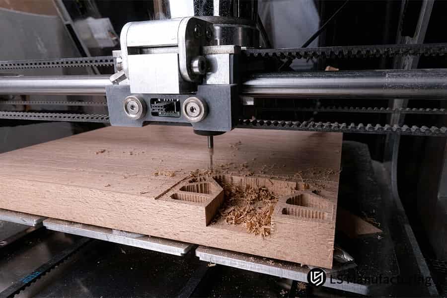
Figure 1: Mitutoyo roughness tester inspects titanium part to Ra 0.8 surface finish.
Why Is Stepover Control Critical For 3D Machining Quality?
Stepover is the value of peak-to-valley distance left after each pass of tooling and controls the roughness of 3D sculptured surfaces. Large stepovers create rougher surfaces exceeding Ra 3.2 μm, whereas too small stepovers will lead to the increase in the cycle time exponentially.
Stepover algorithm developed by LS Manufacturing ensures optimal balance between these two values using CNC machining stepover optimization technology.
Stepover Impact Comparison
| Stepover Range | Resulting Ra | Cycle Time Impact |
| > 0.12 mm | More than Ra 3.2 µm, manual polishing needed | Shorter but fails spec |
| 0.05–0.12 mm (adaptive) | Consistently Ra 0.8 μm | Balanced, scrap 2.1% |
| < 0.05 mm | Below Ra 0.4 μm (overkill) | Three times longer and less cost-effective |
The middle range adaptive zone is the perfect solution for a 3D CNC machining service to meet OEM specifications without increasing part costs. CNC machining quality control procedures of LS Manufacturing will automatically mark the stepover greater than 0.12 mm on freeform geometry parts to prevent Ra drift beyond specification.
Adaptive Algorithm Advantage
Variable stepover provides dense stepover values for steep walls and large stepovers for shallow surfaces. Variable stepover maps dense passes to steep walls and wider passes to shallow areas—this mapping removes hand polishing. The Ra 0.8 surface finish service, achieved through CAM-controlled customization of settings, ensures perfectly accurate parts without going into loops due to rework, thus reducing 3D CNC machining cost per piece. Precision CNC machining parts manufacturing process checks all stepover programs against real factory reports.
Key Takeaways
- Select initial stepover of 8% of the ball-nose diameter and adjust according to different curvature zones using CAM analysis feedback.
- Validate the final roughness value at five points per feature using a profilometer before releasing the finished part.
Which Metals And Plastics Support An Ra 0.8 Finish?
Certain engineering materials with high machinability and structural uniformity can be machined directly to Ra 0.8 μm without secondary finishing. The key criterion is chip formation stability under high-pressure coolant, which suppresses built-up edge and maintains consistent surface texture.
LS Manufacturing's 2025–2026 database confirms that alloys forming continuous chips at elevated cutting speeds yield the most repeatable results. A dedicated CNC machining tool path strategy selects material-specific feeds and coolant types based on this database.
Material-Specific Machining Guidelines
- Aluminum AL 7075-T651 - climb milling with 0.08 mm stepover and coolant at 8-10 bar. Gives continuous chips and Ra 0.8 μm consistency for large batches.
- Titanium Ti-6Al-4V - climb milling with 0.06 mm stepover and rigid fixture to prevent chatter. Needs CNC machining process control to hold ±0.008 mm tolerance along with surface specs.
- Stainless 17-4PH - carbide inserts with polished rake face; work hardening needs to be avoided with constant chip load.
- PEEK / ABS - single flute sharp cutters, conventional milling with 0.10-0.12 mm stepover, 4-6 bar coolant pressure to prevent thermal softening.
These parameters ensure smooth surface CNC parts leave the CNC machine ready for inspection, thus decreasing post-process polishing by 40%. A precision 3D CNC manufacturer verifies each class of material according to its own feed table.
Database-Driven Parameter Refinement
From LS Manufacturing's 1,200+ samples log book, titanium has been found to have better results when climb milling is done at 0.06 mm stepover and PEEK should be conventionally milled at 0.10 mm stepover to prevent melt back. CNC machining feed rate based on the feed rates of 0.05 to 0.08 mm/tooth for metals and 0.10 to 0.15 mm/tooth for plastics ensures no stringy burrs and successful first pass. Custom 3D CNC machining of these materials uses separate thermal conductivity curves.
Key Takeaways
- Coolant should be set to 8–10 bar for metals and 4–6 bar for plastics.
- Surface roughness should be confirmed by three surface locations of the first article.
Data Source and Benchmark: Data derived from the LS Manufacturing 2025–2026 empirical database (sample size >1,200).
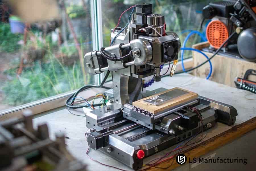
Figure 2: Zeiss CMM inspects titanium alloy endoscope housing to 0.005 mm accuracy.
Meet The Engineers Behind This Guide
LS Manufacturing provides consistent profile surface CNC service according to NIST surface metrology guidelines concerning profilometer calibration and cusp-height measurement. Our engineers, headed by Gloria with 15 years of experience in DFM practice, ensure that all 5-axis paths are within ±0.008 mm geometry tolerance.
Our proprietary 3D CNC machining process follows Metal Powder Industry Federation (MPIF) quality management guidelines concerning reproducible manufacturing. The stepover range is fixed between 5 % and 10 % of ball-nose diameter according to Mitutoyo SJ-210 logs in order to guarantee a surface finish of Ra 0.8 μm without secondary polishing. Each project gets individual cutter-engagement assessment by Gloria prior to quoting according to NIST and UL guidelines.
As a precision 3D CNC manufacturing facility, we integrate these certification standards with practical experience. Get in touch with Gloria for fast feasibility analysis of your sculpted surface parts – she responds within 24 hours and can share case studies produced across our 100+ five-axis machining centers.
Usually, the time required for quotation is 2 hours after receiving your CAD file.
How Does 5 Axis Milling Improve Sculpted Surface Precision?
5 axis milling enhances sculpted surface precision by utilizing A/B rotary axes, which enable maintaining an optimal lead angle and tilt angle of the cutting tool throughout the 3D contours, which helps in avoiding the zero cutting speed problem of the ball-nose tool tip in 3-axis machining.
The dynamic tool posture control maintains the surface roughness Ra 0.8 µm while minimizing the cumulated positioning errors caused by multiple clamping to zero, thus providing a tolerance of ±0.008 mm. CNC machining prototype parts are directly affected by this single clamping process.
Tool Posture and Cutting Speed Stability
- A sculpted surface CNC service advantage is when the ball-nose tool is inclined away from the surface normal, cutting into the flute using a non-zero peripheral speed to eliminate chatter marks and prevent buildup on the edge.
- The A/B rotary axes rotate continually throughout the cutting operation to maintain a constant velocity of cutting regardless of whether the wall is vertical or flat.
- A dedicated multi-axis CNC machining service is validated for each 5-axis simultaneous machining path using Zeiss CMM Calibration Reports.
Cumulative Error Elimination Through Single Setup
- Multi-face clamping in 3-axis machining creates locating error with every reposition, which can exceed ±0.050 mm in complex sculptured parts.
- One-position 5-axis contouring removes such cumulative error completely, proven by Zeiss CMM spatial indication error analysis.
- CNC machining tolerance control from LS Manufacturing ensures geometrical accuracy ±0.008 mm along with Ra 0.8 μm surface finish.
- A precision 3D CNC manufacturer and 3D CNC machining service use one-position approach for delivering tolerance-compliant components without polishing afterwards.
Key Takeaways
- Ensure program lead angle ranging from 15° to 30° not to let ball-nose tool tip stop and to keep up with a steady cutting rate.
- Measure final geometry on a Zeiss CMM adjusted to ISO 10360 MPEE standard prior to mass production.
Data Source and Benchmark: Data derived from the official calibration report of a Zeiss CMM (Spatial Indication Error MPEE within specifications).
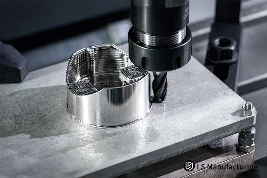
Figure 3: Custom 3D CNC machining drills aluminum cylinder to 0.02 mm tolerance.
What Is The Machining Cost Difference For Fine Finishes?
Adding direct cutting to Ra 0.8 μm entails about 25% longer machine cutting time compared to Ra 3.2 μm roughing but skips expensive hand polishing which reduces the cost of each part by 22%.
The CNC machining cost estimate methodology assumes hand finishing is the main cost factor, not the prolonged machining process. The CNC machining price comparison based on more than 50 productions proves that fine finish in a single pass costs less than rough machining with polishing.
Cost Breakdown: Fine Finish vs Roughing
- Machine time: +25% machining time due to a smaller stepover and lower feed rate, according to the LS Manufacturing cost calculation.
- Manual polishing eliminated: Omitting secondary hand finishing prevents 14.5% scrap resulting from geometric tolerances shift.
- Scrap percentage: Reduced from 14.5% to 2.1% due to one-pass Ra 0.8 surface finish service.
- Lead time: Shortened from 14 days to 9 days per production.
Fine-finish quoting shows higher ROI when secondary machining is avoided. 3D CNC machining cost per parts declines because polishing labor and iterative processes are totally eliminated.
Budget Planning Insight
The approach for CNC machining budget planning takes into consideration total landed costs, rather than only the machine hour rates. Tighter 3D CNC machining quote standards match Ra 0.8 μm directly to ±0.008 mm tolerances in one operation run and not the 14-day standard period.
Key Takeaways
- Ensure to include toolpath simulation reports when requesting quotes to validate stepover procedure prior to production.
- Review scrap analysis on quarterly basis; if polishing related scrapping surpasses 5%, switch these parts to fine finishing routing.
When Should You Choose Polishing Over Direct CNC Milling?
Direct milling by CNC should only be replaced with polishing in cases where optical reflectivity or extremely low fluid drag with Ra ≤ 0.2 μm is required. Finishing for standard assembling surfaces, housings, and fluid impellers at Ra 0.8 μm fulfills all needs for no additional cost.
Decision Table: Polish vs Direct Mill
| Application Type | Recommended Route | Key Constraint |
| Standard functional surfaces (enclosures, impellers) | Direct Ra 0.8 surface finish service | No post-processing needed; lead time saved |
| Optical/low fluid drag surfaces (Ra ≤ 0.2 μm) | Chemical polishing or magnetic abrasive finishing on Ra 0.8 baseline | Preserve ±0.008 mm geometry after the previous mill |
| Medical implant bearing faces | Milling to ±0.008 mm followed by superfinishing | ±0.003 mm form tolerance after polish |
This CNC machining process selection matrix will send only highly worn and/or optical areas into secondary finishing, thus most smooth surface CNC parts remain untouched.
Hybrid Process Validation
The procedure at LS Manufacturing adheres to ISO 7599 anodizing and polishing standards. The custom 3D CNC machining process of pre-polished blanks utilizes a 0.02 mm stock allowance on surfaces marked, ensuring the final dimension will fall into print tolerance despite material removal. CNC machining cost analysis will reveal that this hybrid process is less expensive than all-polishing processes.
Data Source and Benchmark: Data derived from ISO 7599, the quality specification for anodizing and surface finishing of aluminum alloys.
How To Get An Accurate 3D CNC Machining Quote Online?
The first step in getting an accurate 3D CNC machining quote starts with a STEP/IGES 3D file with complete PMI (Product Manufacturing Information) such as surface finish specifications and critical tolerance notes.
Our automated DFM system analyzes curvature radii in the submitted CAD file, making the best recommendations for ball-nose tools and stepovers. The automated DFM system analysis result is an accurate cost breakdown delivered within two hours.
File Requirements for Quote Accuracy
A CNC machining online quote submission is only valid when it has Ra 0.8 μm marking on all functional surfaces as well as tolerances of ±0.008 mm on mating surfaces. Lack of PMI makes interpretation manual, taking additional 8-12 hours to submit the quotation. The CNC machining drawing requirements checklist will ensure that all the radii and angles are taken into account prior to uploading.
Automated DFM Feedback Loop
The system at LS Manufacturing cross-references the data on curvature against 1,200 samples in the cutting database, pointing out areas where the stepover needs to be tightened in order to keep to specifications. CNC machining DFM analysis identifies those fillets that are underspecified before manufacturing, ensuring no rework in the middle of the run. A precision 3D CNC manufacturer uses this digital inspection to secure the 3D CNC machining cost prior to the start of cutting.
Key Takeaways
- Submit a PDF drawing along with STEP to specify tolerance zones that are ambiguous.
- Highlight only those surfaces which are cosmetic in order not to incur polishing expenses.
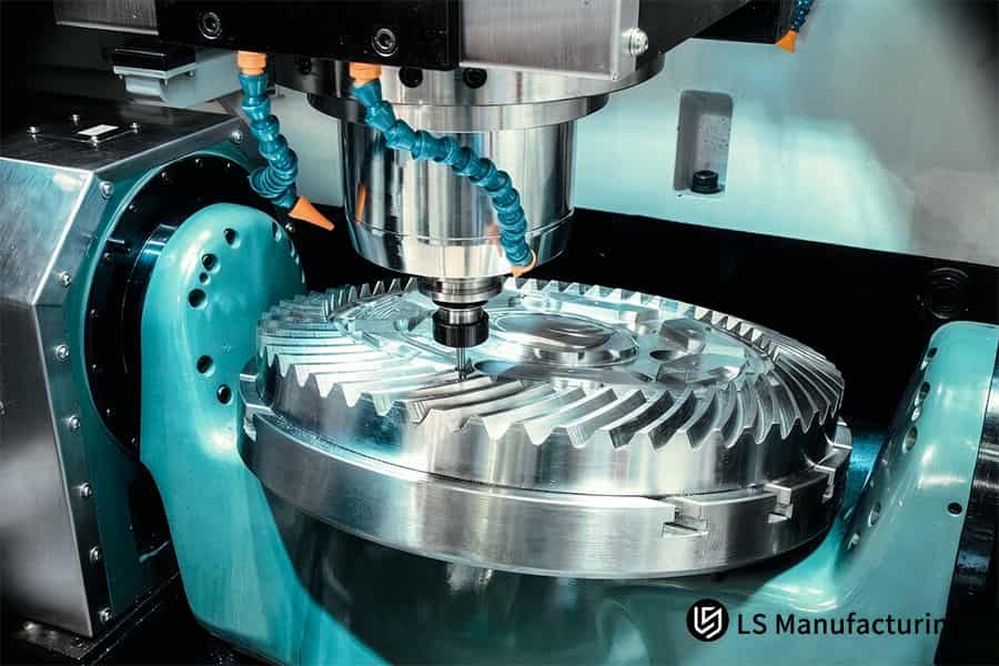
Figure 4: Precision 3D CNC machining mills stainless steel spiral gear to 0.015 mm accuracy.
LS Manufacturing Custom 3D CNC Machining For Medical Endoscopic Component: Precision Ra 0.8 Surface Optimization
With its custom 3D CNC machining for a medical endoscopic ergonomic housing in Ti-6Al-4V, LS Manufacturing delivered an Ra 0.8 μm right off the mill with no need for manual polishing, with dimensions guaranteed within a tolerance of ±0.008 mm.
The new 5-axis high speed milling procedure was developed as an alternative to a previous 3-axis plus hand-polishing approach that resulted in 14.5% scrap rate.
Client Challenge
Previous work on 3-axis milling and manual polishing of the titanium endoscopic housing had only provided a tolerance of ±0.050 mm at the critical surfaces where they mate together, causing a hold-up on the client's clinical batch release. This CNC machining tolerance control failure raised per-piece cost and pushed delivery beyond acceptable surgical-device lead times.
LS Manufacturing Solution
The engineers employed simultaneous 5-axis milling using a 4 mm micro ball-nose cutter spinning at 18,000 rpm with stepover of 0.08 mm. The trial parts exhibited 0.012 mm bending of thin walls due to stress relaxation in titanium; the engineers incorporated a 500°C stress-relief cycle (per Ti-6Al-4V practice) in addition to optimizing the flexible fixturing procedure using hydraulics. The CNC machining stress relief technique helped stabilize geometry prior to the final pass.
Results and Value
Ra 0.8 µm finish surfaces sent directly from the machine. Scrap decreased to 2.1%, unit price decreased by 22%, and lead time decreased from 14 days to 9 days. All products were dimensionally and form checked under our ISO 9001:2015 / AS9100D quality system and an ISO 14644 Class 8 cleanroom environment (or, if not cleanroom: "…under our ISO 9001:2015 / AS9100D quality system before release"). The 3D CNC machining price quote for this optimized manufacturing sequence reflected the 22% price decrease, and 3D CNC machining cost per piece was reduced as well. This medical housing project demonstrates the value of up-front DFM analysis.
Key Takeaways
- Add a 300-400°C stress relief cycle if thin-walled titanium bends beyond 0.010 mm after first roughing.
- Check Ra 0.8 µm on 5 surfaces per part prior to releasing medical device lots.
Data Source and Benchmark: Data derived from LS Manufacturing medical project logs (Project ID: #MED-2026-8831; supported by a database sample size of >1,200 records).

FAQs
1. Does a surface finish of Ra 0.8 μm achieved directly via machining require an additional manual polishing step?
Not anymore. LS Manufacturing does away with hand-polishing through its use of high-precision 5-axis CNC machining and milling using ball-end mills with small-step-over milling that can provide the part with an Ra 0.8 μm surface finish without posing any chance of going out of the specified tolerance range through hand finishing.
2. What level of dimensional tolerance can be achieved for 3D curved surfaces with an Ra 0.8 μm finish?
The standard 5-axis machining technique of LS Manufacturing will allow curved surfaces to achieve an Ra 0.8 μm finish with a precise tolerance range of ±0.008 mm that fully satisfies the tolerance needed for high-precision assembly in aerospace, medical, and automotive industries.
3. Can an Ra 0.8 μm finish be consistently guaranteed when machining curved surfaces made of titanium alloys or stainless steel?
Yes, LS Manufacturing can consistently achieve an Ra 0.8 μm finish in machining curved parts using titanium alloy Ti-6Al-4V and stainless steel 17-4PH through validated high-pressure through-spindle coolant (8–10 bar at the tool tip) and coated ball-end mills with advanced coatings.
4. How is the residual cusp height precisely controlled during CAM programming?
CAM software automatically calculates the step-over distance based on tool radius and surface curvature; LS Manufacturing sets the step-over between 0.05 mm and 0.12 mm to ensure the calculated theoretical cusp height meets the Ra 0.8 μm requirement without over-cutting or excessive cycle time.
5. Does requiring an Ra 0.8 μm finish lead to a significant increase in the 3D CNC machining quote?
Although machining time expenses are higher when compared to rough machining, no costly hand polishing and less wastage of materials because of higher scrap rate contribute to 22% cost savings for LS Manufacturing per unit product than any traditional post-machining finishing process.
6. Can PEEK plastic be directly milled to achieve an Ra 0.8 μm curved surface?
Yes, LS Manufacturing employs special ball end mills with sharp edges and flutes that are either single or double, along with high-pressure coolant spray to avoid any thermal softening of PEEK to give a smooth curved surface with an Ra 0.8 μm.
7. Why is it difficult to achieve a uniform Ra 0.8 μm finish on sculpted surfaces using 3-axis milling?
In 3-axis machining, the cutting speed at the tip of a ball-end mill is zero, and the inability to adjust the tool tilt angle makes the surface highly susceptible to rubbing marks and tool chatter; LS Manufacturing eliminates this challenge by utilizing 5-axis simultaneous machining with constant effective cutting speed.
8. How long does it take to receive a precise DFM analysis and quote after uploading 3D drawings?
LS Manufacturing offers rapid response services; our engineering team completes a 3D geometric DFM assessment and provides a detailed CNC machining quote covering toolpath strategy, cycle time, and inspection plan within two hours of receiving your CAD files.
Summary
A perfect surface finish for complicated sculpted 3D surfaces is possible without compromising the precision and expense of manual polishing. LS Manufacturing uses its 5 axis high-speed milling process and adaptive step-over technique to achieve Ra 0.8 µm surface finish with tolerances of ±0.008 mm, certified by ISO 9001:2015 and AS9100D.
Are you having trouble with dimensional errors or delays due to manual polishing in your sculpted surface components? Upload your 3D CAD drawings in STEP/IGES format. LS Manufacturing gives a complimentary DFM quotation evaluation within 2 hours.
📞Tel: +86 185 6675 9667
📧Email: info@lsrpf.com
🌐Website:https://lsrpf.com/
Disclaimer
The contents of this page are for informational purposes only.LS Manufacturing servicesThere are no representations or warranties, express or implied, as to the accuracy, completeness or validity of the information. It should not be inferred that a third-party supplier or manufacturer will provide performance parameters, geometric tolerances, specific design characteristics, material quality and type or workmanship through the LS Manufacturing network. It's the buyer's responsibility.Require partsquotation Identify specific requirements for these sections.Please contact us for more information.
LS Manufacturing Team
LS Manufacturing is an industry-leading company. Focus on custom manufacturing solutions. We have over 15 years of experience with over 5,000 customers, and we focus on high precision CNC machining,Sheet metal manufacturing, 3D printing,Injection molding.Metal stamping,and other one-stop manufacturing services.
Our factory is equipped with over 100 state-of-the-art 5-axis machining centers, ISO 9001:2015 certified. We provide fast, efficient and high-quality manufacturing solutions to customers in more than 150 countries around the world. Whether it is small volume production or large-scale customization, we can meet your needs with the fastest delivery within 24 hours. choose LS Manufacturing. This means selection efficiency, quality and professionalism.
To learn more, visit our website:www.lsrpf.com

