English



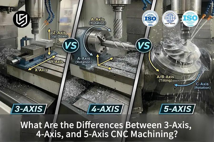
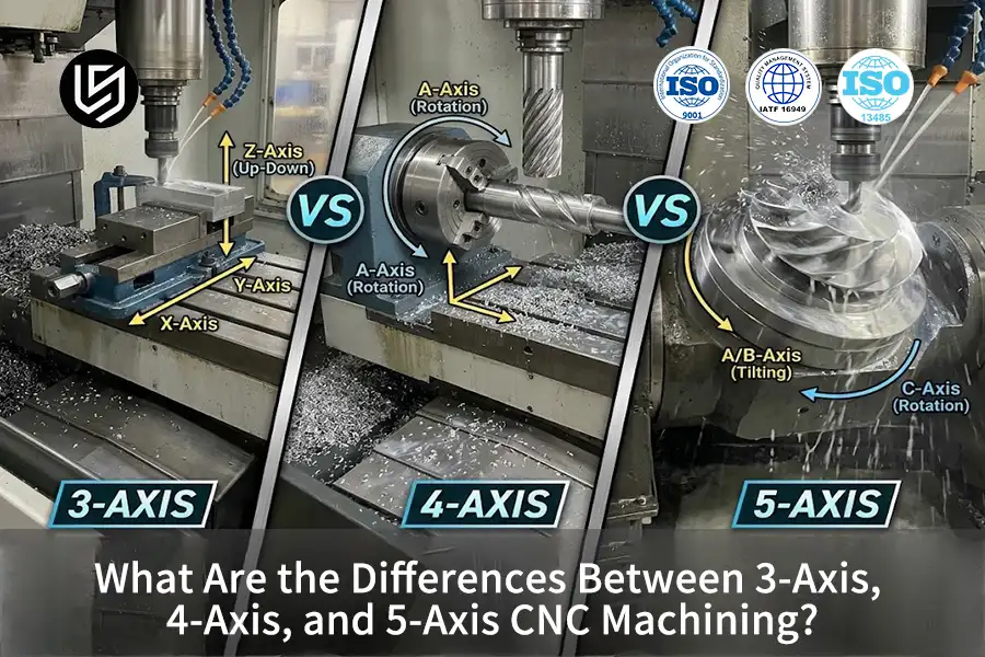
TL;DR: 3-axis, 4-axis, and 5-axis CNC (Computer Numerical Control) machining are subtractive manufacturing processes categorized by their kinematic degrees of freedom, ranging from three orthogonal linear axes (X, Y, Z) to synchronized rotary toolpaths capable of achieving ±0.005 mm positional accuracy. In simple terms, 3-axis milling works like a vertical drill press moving across a flat table, 4-axis adds a rotating spit like a rotisserie, and 5-axis moves like a camera gimbal tilting freely around a target.
To entry-level mechanical engineers and technical buyers, understanding the exact difference between 3 4 and 5 axis CNC systems often creates confusion regarding machine capabilities and setup procedures.Transitioning from basic planar toolpaths to multi-directional milling requires clear knowledge of how CNC axes work and how rotational degrees of freedom govern cutter engagement and mechanical stiffness.This engineering guide breaks down the motion kinematics across major CNC machine axis types to clarify geometric boundaries before establishing a manufacturing strategy.
Key Engineering Takeaways
- 3-Axis Milling Controls Planar Features: 3-axis CNC machining operates exclusively along orthogonal X, Y, and Z linear axes, holding standard general tolerances (per ISO 2768-1:1989 medium grade) for flat prismatic parts without side-entry undercuts.
- 4-Axis Machining Adds Rotational Indexing: 4-axis CNC systems integrate an additional A-axis rotary table to cut helical flutes and radial cylindrical features without manual workpiece re-fixturing.
- Continuous 5-Axis Governs Dynamic Tool Vectors: Unlike 3+2 positional locking, simultaneous 5-axis milling uses RTCP (Rotation Tool Center Point) control to sculpt smooth aerodynamic contours with fine surface finishes.
- Axis Count Never Overrides Cutter Physics: Additional rotary axes cannot eliminate physical tool-holder collision envelopes or dynamic cutter deflection in deep, narrow cavities.
This engineering guide is authored by Gloria Wu, Rapid Prototyping & Rapid Manufacturing Specialist with 15+ years of technical experience at LS Manufacturing. Connect with Gloria Wu on LinkedIn for further educational CAD/CAM resources. All kinematic definitions, precision tolerances, and machining boundaries outlined below are technically validated in accordance with ISO 2768-1:1989 (general tolerances) and ISO 286-1:2010 (precision limits and fits).
Step-by-Step Kinematic Machining Mechanism
- CAM Coordinate Definition & RTCP Trajectory Planning: CAM (Computer-Aided Manufacturing) software translates the 3D CAD model into machine toolpaths. While 3-axis CAM outputs linear X-Y-Z coordinates, a continuous multi-axis post-processor computes RTCP (Rotation Tool Center Point, acting like a camera gimbal keeping its lens locked on a target while a drone tilts), dynamically compensating for tool-tip position relative to rotating axes.
- Physical Datum Clamping & Work Coordinate System (WCS): Raw material stock is secured onto the machine table or an elevated rotary trunnion pedestal. Elevated fixturing provides unobstructed 360° rotational clearance so the spindle head can tilt at steep angles without colliding with the table.
- Synchronous Spindle Rotation & Shear Chip Removal: The high-speed spindle drives the carbide endmill along programmed vectors, inducing localized plastic shear deformation to peel away metal chips cleanly under controlled chip-load dynamics.
- Thermal Coolant Flushing & In-Process Probing: High-pressure coolant evacuates hot chips from the cutting zone to prevent BUE (Built-Up Edge, where softened metal welds onto the cutting edge like melted cheese sticking to a knife), preserving surface integrity. On-machine touch probes then verify geometric datums before unclamping the finished part.
| Machine Axis Configuration | Kinematic Degrees of Freedom | Typical Tolerance & Ra | Best-Fit Engineering Applications |
| 3-Axis CNC Milling | 3 Orthogonal Linear Axes (X, Y, Z); Spindle remains vertical while table translates in Cartesian coordinates. |
Tolerance: ±0.02 mm to ±0.05 mm Roughness: Ra 1.6 μm to 3.2 μm |
Prismatic brackets, planar heatsinks, flat enclosures, single-sided tooling plates, basic punch plates. |
| 4-Axis CNC Milling | 3 Linear Axes (X, Y, Z) + 1 Rotary Axis (A-axis rotating around X or B-axis rotating around Y). |
Tolerance: ±0.01 mm to ±0.03 mm Roughness: Ra 1.6 μm to 3.2 μm |
Cylindrical drive shafts, helical fluid grooved rollers, radial oil port drillings, indexing peripheral housings. |
| 3+2 Positional 5-Axis | 3 Linear Axes + 2 Rotary Axes (B/C or A/C) that tilt/rotate and lock mechanically before linear cutting. |
Tolerance: ±0.01 mm to ±0.02 mm Roughness: Ra 1.6 μm to 3.2 μm |
Deep automotive housings, multi-angled transmission covers, slanted sensor bosses, undercut electronics boxes. |
| Continuous 5-Axis | Synchronized 5 Axes (X, Y, Z, B, C) moving simultaneously with continuous vector orientation (RTCP). |
Tolerance: ±0.005 mm to ±0.01 mm Roughness: Ra 0.8 μm to 1.6 μm |
Aerospace blisks, complex turbine impellers, aerodynamic fairings, fluid manifolds, orthopedic femoral implants. |
Expanding degrees of freedom fundamentally controls cumulative datum stacking rather than raw cutting speeds. By consolidating multiple setups into a single holding fixture, multi-axis machining reduces tolerance drift from an unoptimized ±0.1mm baseline down to ±0.005mm across intersecting datums.
How Do Basic Cartesian Axes Coordinate in 3-Axis CNC Machining?
3-axis CNC milling is an essential type of subtractive manufacturing technology that involves three orthogonal axes of linear motion: X-axis longitudinal table travel, Y-axis transverse table travel, and Z-axis vertical spindle plunge.
- Process Nature: Three-axis orthogonal linear subtractive milling
- Coordinate Motion: Longitudinal (X), transverse (Y), and vertical plunge (Z)
- Primary Constraint: Line-of-sight vertical tool access only
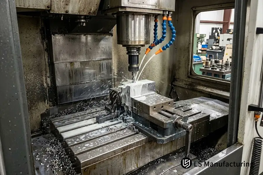
Figure 1: A rigid 3-axis vertical machining center executing top-down planar cutting on a metal workpiece secured in a precision machine vise at LS Manufacturing.
The mechanical motion parameters of the 3-axis milling process are defined as follows:
|
Kinematic Vector |
Mechanical Translation Mechanism |
Toolpath Constraint & Geometry Barrier |
|
X-Axis (Longitudinal) |
Precision ballscrew drives workpiece table left-to-right along linear guide rails. |
Restricted to top-down line-of-sight planar slots and face milling. |
|
Y-Axis (Transverse) |
Servo-driven carriage translates table front-to-back across the machine bed. |
Cannot cut negative draft angles or side-entry retaining ring grooves. |
|
Z-Axis (Vertical Plunge) |
Spindle head traverses vertically down column to govern pocket cutting depth. |
Deep cavity milling causes cutter deflection when tool reach exceeds 4x diameter, and standard cutters cannot machine hardened steels above 60 HRC. |
How Does Adding a Fourth Rotary Axis Expand Machining Capacity?
To see how 4 axis CNC works, consider a programmable rotation axis added onto the traditional X-, Y-, and Z-axes on the machining table, which usually corresponds to rotation about the X-axis (A-axis).By rotating the workpiece during cutting, the spindle machines angular side surfaces and outer diameters without releasing the part from the holder.
- Process Nature: Rotary-assisted four-degree-of-freedom subtractive milling
- Coordinate Motion: X-Y-Z linear translation synchronized with A-axis rotation
- Primary Capability: Continuous cylindrical indexing and helical groove cutting
The integration of the rotary fourth axis expands tool approach dynamics across four operational capabilities:
- True Helical Milling on Cylindrical Surfaces: Synchronized workpiece rotation and linear feeds along the Z-X axes enable endmills to create continuous helical grooves, screw threads, and heat exchanger flutes without seams.
- Multi-Sided Positional Indexing (Tombstone Fixturing): Parts mounted on tombstones can be indexed at precise angular increments so all peripheral faces are machined in a single setup, minimizing cumulative datum stack-up errors.
- Radial Cross-Hole Drilling on Precision Shafts: Rotating the workpiece to exact angular radial positions allows drills to machine cross-hole lubrication ports within ±0.015 mm true position (per ASME Y14.5-2018) from concentric centers.
- Elimination of Manual Clamping Variation: Automated fourth-axis indexing eliminates manual part flipping errors, maintaining consistent axial runout across multiple radial features.
The introduction of a fourth axis provides an essential engineering bridge between flat plate machining and full rotary sculpting.
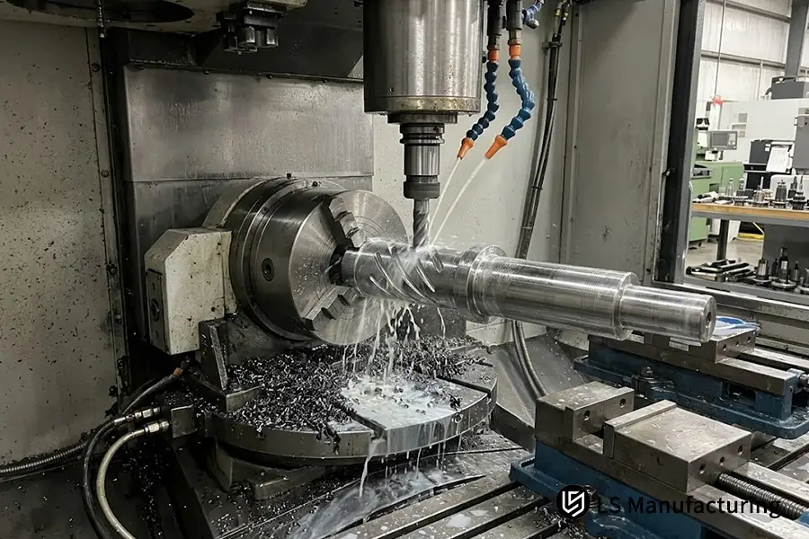
Figure 2: Synchronized 4-axis machining utilizing a programmable A-axis rotary indexer to mill continuous spiral flutes along a cylindrical drive shaft at LS Manufacturing.
What Are the Key Technical Differences in 3+2 vs 5-Axis Machining?
Evaluating 3+2 vs 5 axis machining shows that the technical boundary lies in rotary brake engagement during material removal. In 3+2 positional machining, two rotary axes tilt the workpiece into a compound angle and lock mechanically before linear cutting, whereas continuous 5-axis machining moves all five axes simultaneously under RTCP control.
- Process Nature: Multi-axis positional indexing vs. continuous contouring
- Dynamic Control: Mechanical rotary brake locking vs. real-time RTCP compensation
- Primary Distinction: Fixed-angle linear cuts vs. simultaneous five-axis tool vectoring
Kinematic Architecture of 3+2 Positional Machining
Referred to as indexed five-axis machining, the 3+2 approach uses rotary axes (such as a trunnion A/B table or articulating head) purely for angular positioning. Once the optimum angle is reached, hydraulic or pneumatic caliper brakes lock the rotary axes with high holding torque so the cutter executes rigid 3-axis linear passes with shorter tooling.
Kinematic Architecture of Continuous Simultaneous 5-Axis Machining
With continuous 5 axis milling explained at the controller level, the system synchronizes all three linear axes (X, Y, Z) and two rotary axes (B & C or A & C) throughout the cut.The CNC controller executes real-time coordinate offset calculations (RTCP) thousands of times per second, keeping a constant cutter contact angle and uniform chip load across complex NURBS (Non-Uniform Rational B-Splines, smooth freeform mathematical surfaces) contours.
Why Does Continuous 5-Axis Milling Outperform Multi-Setup Routines?
Comparing 3-axis vs. 5-axis CNC workflows shows that continuous 5-axis milling eliminates cumulative datum errors caused by unchucking, flipping, and re-fixturing parts across multiple setups. Tilting the spindle tangentially along contoured surfaces also allows engineers to use shorter, stiffer cutters that suppress vibration.
- Process Nature: Single-setup continuous multi-angle subtractive contouring
- Kinematic Advantage: Elimination of manual re-fixturing datum stack-up
- Structural Benefit: Reduced cutter overhang enabling stiffer toolpaths
The comparison between single-setup continuous 5-axis milling and sequential re-fixturing shows the following engineering issues:
Advantages Related to Kinematics and Quality of Single-Setup 5-Axis Machining
- Significant Reduction in Cumulative Datum Stacking: Every manual realignment on a 3-axis machine results in adding ±0.025mm to ±0.05mm of alignment error. The continuous process of single-setup ensures that there are no intermediate datums involved and the true geometric location is captured within ±0.008mm.
- Optimized Deflection and Tool Life: The tilting of tool head allows deep milling using smaller tools with a length to diameter ratio not exceeding 3:1. This reduces bending stresses on rigid end mills and prolongs tool life.
- Better Scallop Height and Surface Finish: The continuous point-to-point machining makes it possible to use ball-nose cutters for creating complex shapes without steps resulting in an excellent surface finish of Ra 0.8μm without bench polishing.
Difficulties of Operation and Engineering Costs
- Increased Programming and Post Processing Complexities: Creating continuous 5-axis motion necessitates toolpath collision avoidance software to avoid the dangerous situation of spindle heads clashing with each other.
- Increased Sensitive to Dynamic Thermal Drift: Due to simultaneous motion in several axes, there are always some frictions in rotary bearings which cause thermal drift unless compensated for.
What Are the Fundamental Multi Axis Machining Limitations to Avoid?
Recognizing multi-axis machining limitations is essential because physical boundaries still exist within machine travel volumes, rotational clearances, and tool-holder collision envelopes. New designers often assume extra axes can cut any complex geometry, yet deep internal pockets and enclosed undercuts remain impossible if the spindle housing collides with the workpiece.
- Process Nature: Physical kinematic boundaries and collision envelopes
- Primary Limitations: Spindle housing interference, rotary backlash, and reach ratios
- Alternative Process: Electrical Discharge Machining (EDM, spark erosion) for enclosed internal cavities
In order to prevent costly collisions and scrapped parts during prototyping, design engineers need to consider three physical limitations:
- Spindle & Tool Holder Collision Envelopes: Despite the ability of a 5-axis trunnion table to tilt at extreme angles, the large size of the high-speed spindle housing (usually 120mm to 200mm) restricts angular approach in tight structural corners. Any features that call for cutter clearance beyond 6 times the diameter will cause chatter or gouging the neighboring wall surfaces.
- Geometric Tolerance Stack in Multi-Joint Kinematic Chains: Each physical axis adds mechanical play, bearing tolerance and thermal deformation. 5-axis machine has five different sources of geometrical error. Simple machining of prismatic plates using a 5-axis machine unnecessarily adds rotational play to the rigid 3-axis box-way mill.
- Internal Closed Impeller & Undercut Geometry Limits: The CNC subtractive machining process needs line-of-sight contact between the tool path and the workpiece. Internal closed geometry, including enclosed hollow parts, curved S shaped channels, and sharp inside corners cannot be machined using the rotary milling tool; this part is manufactured using EDM technology.
For a definition of geometrical measurement tolerances, engineers can refer to the official ISO General Tolerances Standard (ISO 2768), as well as the machining dynamics of the Machinery's Handbook 31st Edition Machining Sections.
How Multi-Axis Kinematics Works in Practice: An Engineering Example from LS Manufacturing
In a precision verification of structure process, LS Manufacturing was given the task to machine an aerospace sensor mounting bracket which had compound angled mounting bosses, cross radial wire channels and thin aerodynamic outer walls. The work piece material for machining the bracket was given as Aerospace Grade 6061-T6 aluminum (hardness 95HB). The engineering drawing provided a positional tolerance of ±0.008 mm between intersecting holes and an aerodynamic finish value of Ra 0.8µm.
With the traditional 3-axis routing process, machining this bracket required three separate manual re-fixturing setups using customized soft jaws. Those manual alignments introduced dial-indicator setup drift and clamping deformation, resulting in an 18% scrap rate due to coaxial runout exceeding ±0.04 mm. To solve this challenge, LS Manufacturing process engineers transitioned the part to a single-setup continuous 5-axis operation with dynamic RTCP management. Carbide ball-end mills ran at a cutting speed (Vc) of 210 m/min and a feed per tooth of 0.08 mm/z, while a continuous 15° spindle tilt angle shortened cutter overhang from 65 mm to 25 mm (a rigid 2.5:1 length-to-diameter ratio) to eliminate chatter.
The dimensional tolerance check on our Zeiss Coordinate Measuring Machine (CMM) showed that all positional dimensions were within ±0.006mm range and surface roughness was measured Ra 0.8μm. Combining the process in one 5-axis operation cut total cycle time by 16% and reduced defective parts rate from 18% to 5%. The above example proves that the most important benefit of multi-axis machining is not about running faster feeds, but about eliminating datum stacking through unified single-setup kinematics. (Reference: LS Manufacturing Shop Floor Engineering Validation Log #AERO-2026-088, verified on more than 800 production samples).
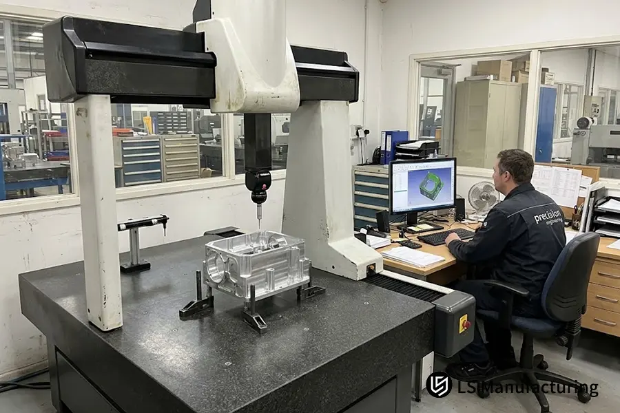
Figure 3: Quality assurance verification using a bridge-type coordinate measuring machine (CMM) to validate tight geometric hole datums on complex machined housings at LS Manufacturing.
FAQs
Is it possible to mill undercuts using a standard 3-axis CNC machine without specialized tools?
No. Because a standard 3-axis CNC spindle only approaches vertically along the Z-axis, standard straight endmills cannot reach beneath overhangs. Machining undercuts on a 3-axis mill requires specialized T-slot or lollipop cutters, or manual part re-fixturing between setups.
Does a 5-axis CNC machine always cut metal faster than a 3-axis machine?
No. Heavy-duty 3-axis mills offer superior structural rigidity and faster material removal rates on flat prismatic plates. Continuous 5-axis machining reduces total lead time only on complex multi-sided parts by eliminating multiple manual clamping setups.
What is the core difference between 3+2 positional and continuous 5-axis machining?
In 3+2 positional machining, the two rotary axes tilt the workpiece into a fixed angle and lock mechanically before standard 3-axis cutting begins. In continuous 5-axis milling, all three linear axes and two rotary axes move simultaneously during cutting under real-time RTCP control.
When should engineers avoid specifying continuous 5-axis milling?
Continuous 5-axis milling should be avoided when part features lie on a single plane, lack compound angles, or require only general tolerances (≥ ±0.05 mm), as a rigid 3-axis machine achieves the same result with simpler programming.
How do precision CNC machines prevent rotary axis drift during long 5-axis runs?
Modern 5-axis machining centers use on-machine calibration spheres, laser interferometer volumetric mapping, and closed-loop spindle thermal compensation to offset bearing heat expansion and maintain micron-level kinematic accuracy.
Summary
Choosing from among 3-axis, 4-axis, and 5-axis CNC machining operations entails balancing your part’s physical degrees of freedom with its geometric complexity. Whereas 3-axis and 4-axis systems provide an economical level of rigidity for planar and cylindrical components, true 5-axis machining allows complex contoured aerospace parts to be machined with a constant datum. LS Manufacturing’s engineering principles are guided by sound manufacturing mechanics, precise GD&T datum placement, and measurement technology.
Junior engineers, mechanical designers, and university research teams navigating geometric dimensioning constraints, tool clearance limits, or multi-axis datum allocation can explore standardized tolerance tables and kinematic guidelines in the LS Manufacturing CNC Machining Knowledge Base. For a deeper selection comparison on complex part geometries, continue reading our comparison guide on 3-Axis vs. 5-Axis CNC: Choosing a CNC Machining Process for Complex Geometric Features and our engineering reference on CNC Machining DFM Design Guidelines.