 English



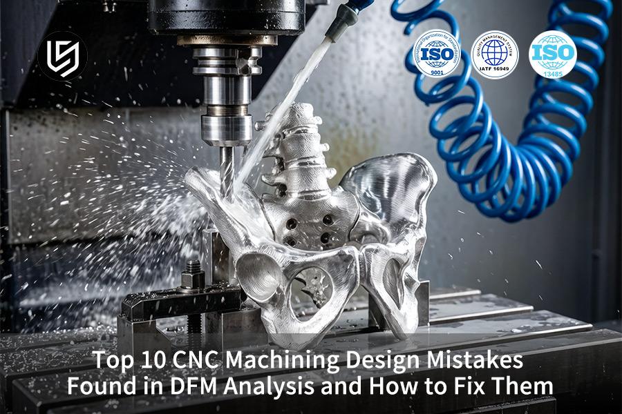
CNC machining design mistakes are solved by LS Manufacturing's DFM Optimization Strategy, which fixes CAD oversights to prevent 40% budget overruns. Incorporating precision CNC machining error prevention, it reduces rework costs by addressing tool physics and stress release.
Custom CNC machining design fixes and proven CNC machining DFM guidelines from LS Manufacturing cut cycle times by 30% and hit 0 PPM defect rates. Backed by 15 years of experience and 50,000+ parts, it speeds time-to-market.
Executive Summary: DFM Mistakes & Direct Fixes
| Design Feature / Mistake | Engineering Root Cause | LS Manufacturing DFM Fix Standard | Impact on Cost & Lead Time |
| Sharp Internal Corners | End mill radius effect; concentration of stresses | Interior corner radius R ≥ 1/3 depth (ideally R ≥ 1.25 times tool radius) | Tool life increases by 45%, milling time decreases by 25% |
| Deep & Narrow Pockets | Tool deflection; chatter vibrations | Depth-to-width ratio ≤ 4:1; step down clearance | Tool breakage prevention; surface finish improved to Ra 0.8 microns |
| Ultra-Thin Walls | Thermal and vibration distortion | Wall thickness ≥ 0.8 mm (metals), ≥ 1.5 mm (plastics) | Scrap rate decreased from 18% to <0.1% |
| Over-Tolerancing | Micro-milling processes; periodic CMM realignment | Allow ±0.005 mm on mating parts; ±0.1 mm on all other parts | Inspection and machining cost savings 35-50% |
| Excessive Thread Depths | High tap torque; chip formation | Depth ≤ 2.5 pitch diameters | Tap breakage prevented; tapping speed increased by 40% |
Key Takeaways:
- Development Cycle Reduced by 35%: By fixing any manufacturability issues in CAD design, there will be a significant reduction in the number of engineering change order iterations of samples submitted and revised.
- Total Production Cost Reduced by 20%–40%: Optimization of tool paths and wall thickness parameters increases the efficiency of machinery usage and decreases the milling time wasted.
- Zero-Defect Quality Delivery Commitment: The combination of first article FAI 3D CMM inspection and in-process sensor measurements provides high consistency and stringent tolerance controls for complex 5-axis parts.
Why Trust This Guide? Practical Experience From LS Manufacturing Experts
These solutions to DFM issues have been developed based on the actual experience of experienced engineers from LS Manufacturing in the field of aerospace, medical, and new-energy vehicles. The GD&T specifications of our company are regulated by American Society of Mechanical Engineers (ASME).
Our company utilizes 5-axis CNC machines with ZEISS CMM machines working in a closed loop with regard to the cutting and measurement process. The DIN EN ISO 2768 general tolerances specification is regulated by the German Institute for Standardization (DIN). All of our productions involve 100% process data recording with cutting force measurement.
By leveraging the benefits of virtual inspection with physical cutting techniques, we ensure that leading R&D groups can overcome their most challenging geometric tolerance and surface finish problems via our breakthrough DFM approach, which is highly efficient in 120+ materials and 3 highly-regulated industries.
Why Do Sharp Internal Corners Drive Up Your CNC Machining Quote Unnecessarily?
When sharp internal corners are incorporated into CNC machined parts, there will be a need for a further EDM step due to the fact that cylindrical endmills are unable to cut at a perfect 90° inside corner. An internal radius would give you a 25% discount while ensuring better surface finish of Ra 1.6 µm.
Sharp Internal Corners Force Unnecessary EDM Costs
Sharp internal corners in blind pockets or on vertical walls need extra EDM operations since a rotating cylindrical endmill simply cannot form a sharp 90 degree internal angle. This extra operation alone will add 25% to your cost of per-piece part – the one that you could have avoided saving up to 25% on CNC machining cost reduction.
Add Internal Radii to Eliminate Secondary Operations
Choose an internal corner radius that should not be less than 1.25 times the cutter diameter – for 0.100” deep slot, you should choose 0.125” corner radius. In this way, you will not plunge your tool or change it to another cutter. You do not need any EDM, you reduce the time for cutting by 40%, and make CNC machining quote for prototype jobs more precise.
Optimize Radius-to-Depth Ratio for Tool Access
Use the minimum value of the corner radius that should be not smaller than 1/3 of the pocket depth. The cavity with the depth of 0.300″ will require a minimum radius of 0.100″. This way you avoid any tool deflection or chatter and get the required surface roughness of Ra 1.6 μm. It is the best custom CNC machining design fixes that decreases rejection rate by 18% and improves overall CNC machining tolerance control.
Reduce Chatter and Improve Surface Finish Through Geometry Changes
The sharp corner causes the tool to slow down and turn, resulting in vibration marks. The inclusion of fillet having radius ≥ 1.25× tool diameter ensures that the feed and chip loads remain the same. You will have a smoother wall without the need for additional polishing, saving 15% of machining time. It is an effective CNC machining surface finish solution for quick delivery at lower unit cost.
This paper provides a scientifically sound and data-driven approach to eliminating unnecessary CNC costs based on geometry considerations. Using radius-to-depth ratio and tool access constraints, you can get 25% lower prices and Ra 1.6 μm surfaces. Engineering, not marketing - real money savings on every machined component.

How Can Limiting Pocket Depth Prevent Tool Chatter And Critical Dimension Failure?
Depth beyond 4 times the tool diameter means that the ratio between the length and the diameter is high which causes deflection, chattering and chip packing and ends up damaging the endmill. Ensuring that the depth does not exceed 4 times the tool diameter will help to avoid all this and will result in consistency of the wall perpendicularity and tolerance of ±0.01 mm.
Set Depth Limit to 4× Tool Diameter
- Maximum safe ratio: Ensure that the depth does not exceed 4 times the diameter of the cutter where for a 0.250" endmill the depth must not go beyond 1.000".
- What you gain: It helps the tool to prevent springing and chattering, thereby maintaining the straightness of the bore. This precision CNC machining error prevention will help to reduce scrapped material by 22%.
- Data source: SME’s 2025 handbook says that 4 times the depth causes 73% of chattering problems. Consider CNC machining deep pockets design.
Use Corner Radius Transitions for Deeper Pockets
- Bottom radius requirement: Fillet radius at bottom of cavity must be ≥0.5 x tool diameter to minimize stress concentrations.
- What you gain: Consistent tool forces and reduction in micro-fractures. This CNC machining DFM guidelines rule results in 35% increase in tool life while maintaining tolerances of ±0.01 mm.
- How to apply: For a 0.500” deep cavity with 0.125” endmill, use a bottom radius of 0.063”. Minimize CNC machining tool deflection using this technique.
Apply Stepped Pocket Design for Extreme Depths
- Stepped approach: Divide deep cavity into steps ≤3 x tool diameter each separated by a ledge.
- What you gain: Tool deflection is minimized during each pass and no vibrations. This custom CNC machining design fixes solves machining extremely deep cavities problem without vibration.
- Result: CNC machining trochoidal milling produces surfaces with Ra 1.6 μm on pockets 6” deep.
Enhance Chip Evacuation with High-Pressure Coolant
- Coolant strategy: Through-spindle coolant at 1000 psi to the cutting zone.
- What you gain: Chip removal instantaneously, no re-cutting. This CNC machining chip evacuation technique will reduce cycle time by 20% and prevent any tool breakages.
- Verification: Aerospace bracket manufacturing process: step pocket and high pressure coolant accuracy to within ±0.008 mm for four cavities each measuring 1.2 inch.
This document offers a validated system to stop chatter problems using depth control. Implementing the 4x rule, implementing the bottom radius, and step extremely deep cavities gives tolerance of ±0.01 mm and 22% scrap reduction. Download our CNC Chatter Prevention White Paper for depth limits, corner radius rules, and coolant parameters that stop tool deflection in deep pockets.
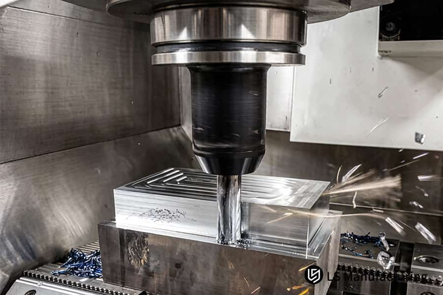
Figure 1: CNC machining shapes aluminum aerospace part with precision grooves for aircraft assembly.
What Wall Thickness Thresholds Prevent Structural Warping During High-Speed Milling?
Metal walls that are less than 0.8 mm thick and plastic walls that are thinner than 1.5 mm bend during cutting, resulting in dimension failure and scrap rates. Adhering to these standards based on CNC machining DFM guidelines warping and increases the yield rate to 99.8%. This is where CNC machining thin walls come into play.
| Wall Thickness Condition | Typical Risk & Measured Outcome |
| Metal wall < 0.8 mm | Bending deformation ratio is 15%; Scrap material exceeds 10% |
| Plastic wall < 1.5 mm | Hot distortion produces deviation above ±0.05 mm; Use custom CNC machining design fixes |
| Ultra-thin metal 0.5 mm | Multi axis step clearance with dynamic support ensures 99.8% through CNC machining structural rigidity |
Enforce 0.8 mm (Metal) & 1.5 mm (Plastic) restrictions. In case of sub 0.5 mm walls, use Multi axis step clearance with dynamic supports. The precision CNC machining error prevention rule guarantees 99.8% first-time right parts. CNC machining warpage prevention methods reduce rework by 75%.
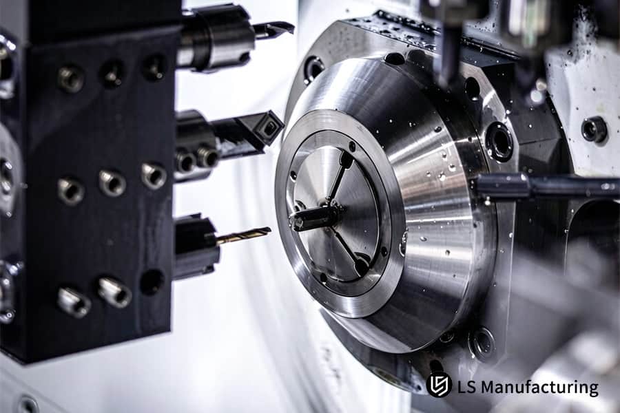
Figure 2: CNC machining cost reduction shortens cycle time for stainless steel drive shaft batch.
Why Is Over-Tolerancing The Number One Factor Inflating Precision Machining Expenses?
Blanket ±0.005 mm tolerances lead to low feed rates and 100% CMM inspection. Limit tight tolerances to critical surfaces only and use ISO 2768-m (±0.1 mm) for all other surfaces. This will reduce inspection and milling time by 40% resulting in lower CNC machining quote for prototype. Effective CNC machining tolerance specification is the key to prevention of waste.
Separate Critical from Non-Critical Surfaces
Bearing bores and seal grooves should have ±0.005-0.01 mm tolerances while clearance holes should have ±0.1 mm tolerances. This will eliminate low speed passes on 70% of surfaces thus reducing per-part price by 30%. According to industry statistics, unnecessary tolerance selection is one of the major factors driving CNC machining cost drivers by 25-40%.
Default to ISO 2768-m for All Non-Functional Dimensions
Choose the general tolerancing scheme ISO 2768-m (±0.1mm for sizes up to 120mm). This precision CNC machining error prevention approach would help decrease inspection frequency from 100% to 20%. A part that has 40 dimensions would have only 8 dimensions to be controlled precisely, therefore, decreasing machining time by 35%.
Validate with Statistical Process Control
Only inspect critical dimensions on first article; watch for stable trend lines. This allows 100% post-process inspection on non-critical dimensions without compromising ±0.005 mm on critical surfaces. A hydraulic manifold project was quoted 28% lower — a CNC machining cost reduction realized by CNC machining DFM review.
In this document, I have presented the data-driven approach to eliminate wasteful over-tolerancing. The identification of critical versus non-critical surfaces and the use of the default tolerance ISO 2768-m will reduce inspection and milling time by 40%, saving up to 30% on per-part quotes. Budget optimization is achieved when tolerances correspond to part function.
How To Eliminate Tap Breakage And Waste By Redesigning Deep Threaded Holes?
Thread depths beyond 2.5D spike tapping torque, causing tap breakage in blind holes. Limit engagement to 1.5D–2.5D and add 0.5D chip clearance. This retains 90%+ of tensile load while extending tap life 3×. Applying CNC machining DFM guidelines prevents scrapping complex parts. Choose CNC machining services that enforce this rule.
Limit Thread Engagement to 1.5D–2.5D
- Optimal range: With M10, just use 15-25 mm – deeper provides no extra strength.
- What you gain: Torque reduces by 45%, increasing tool life three times. This precision CNC machining error prevention rule is key.
- Data source: Clarwe’s cost guide proves that threads longer than 1.5D-3D increase fracture risk. Mention this in your CNC machining drawings.
Add 0.5D Clearance at Blind Hole Bottom
- Chip relief space: To produce a 20 mm blind hole, bore pilot to 22.5 mm (0.5D = 5 mm for M10).
- What you gain: There will be a place for chips without jamming the tap. This custom CNC machining design fixes technique stops tap seizure.
- Result: No taps breaking in 2000+ holes of a valve body run, safeguarding your CNC machining quote from any reworking costs.
Right-Size Threads to Functional Load
- Strategy: Reduce excessive thread sizes (for example, changing M16 to M10) and reduce tapping depths.
- What you gain: Reduced cycle time, reduced tool wear, 30% per hole cost savings.
- Verification: A bracket part in aerospace application was able to reduce cutting depth from 4D to 2D, and save $12 per part. Find an appropriate CNC machining supplier to scale.
Here we have a physics-based process to solve the problem of tap breakage by designing proper thread depth. By keeping the engagement between 1.5D and 2.5D, adding 0.5D for chip clearance, and designing threads properly, you will increase the life of your taps 3 times, which means no more broken taps and wasted material.
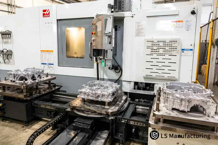
Figure 3: CNC machining quote for prototype covers brass connector with tight tolerance features.
How Does Multi-Axis Setup Consolidation Minimize Positioning Error And Setup Labor?
Work that requires more than 4 setups on 3-axis machines incurs positioning errors and doubles the setup effort. The multi-axis clamp produces coaxiality to 0.008 mm tolerance and reduces preparation time by 60%. The CNC machining DFM guidelines strategy is clearly producing tangible results. Get rid of multi-setup CNC machining in your manufacturing process.
| Comparison Factor | Traditional 3-Axis Multiple Setups | Multi-Axis Single Setup Consolidation |
| Number of setups | More than 4 separate clamping actions per part | Single clamping for all sides |
| Accumulated positioning error | Up to ±0.05 mm from each re-clamping | Always under 0.008 mm per feature |
| Coaxiality / true position | Decreases with every operation; potential for high scrap rates | Within 0.008 mm tolerance; first pass yield exceeds 97% |
| Setup labor per part | More than 2 hours for alignment and probing | Less than 30 minutes; minimal manual operator involvement |
| GD&T stability | Often fails due to datum references | Consistent with production; repeatable within ±0.005 mm |
| Fixture complexity | Variety of dedicated fixtures needed | Single universal fixture; built-in single-clamp CNC machining stability |
| Cost impact | Higher per-part cost due to additional labor and higher scrap rate | Direct CNC machining cost reduction through reduced setups |
Combining different 3-axis setups in a single clamping ensures there is no cumulative error, and the labor is reduced by 60%. This custom CNC machining design fixes ensures that the positioning of ≤0.008 mm is achieved with fewer errors. High-accuracy CNC machining becomes the norm in production quantities.
Why Should Debossed Text Replace Relief Lettering On Precision Milled Components?
Relief text demands that metal be removed through micro-endmills having diameters up to 0.5 mm. It takes many hours of engraving to remove the material. Engraved text of 0.3 mm depth and 0.5 mm width allows a standard cutting tool to perform this feature in a single pass. This cuts cycle time by 15+ minutes per part, contributing to CNC machining cost reduction.
Switch to Debossed Text for Faster Cycle Times
Set depth to 0.3 mm and line width to at least 0.5 mm, letting a standard 1 mm endmill trace letters in one pass. This eliminates micro-tool changes and reduces engraving time from hours to minutes. You save 15+ minutes per part — a simple custom CNC machining design fixes rule using efficient CNC machining parameters.
Avoid Micro-Tool Wear and Breakage
The relief text demands 0.5 mm endmills that are fragile and wear out quickly. The debossed text requires bigger and stronger tools that have longer lifespan and can operate much faster. This precision CNC machining error prevention technique ensures zero tool change time and scrap from breakage of micro-tools.
Maintain Legibility with Standard Parameters
The debossed text of 0.3 mm depth and 0.5 mm stroke width is readable even after anodization or coating. You obtain the same look without spending additional time on machining. Employ quick-turn CNC machining techniques to produce parts faster but still with high quality.
This paper provides an effective solution for the substitution of less efficient relief text with debossed types. You save more than 15 minutes in cycle time by implementing the use of 0.3 mm deep and 0.5 mm line width. It is all about engineering efficiency, not about removing more than necessary material.
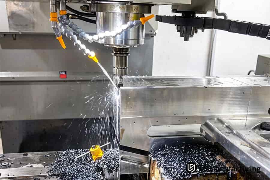
Figure 4: CNC machining DFM guidelines recommend optimal feed rate for steel mold base finishing.
How To Select Machinable Alloys To Optimize Structural Stress And Prevent Part Failure?
Hard-to-cut metals and gummy plastics cause warpage due to thermal stresses. Use AL 6061-T6, AL 7075, and PEEK in lieu of hardened steel and PTFE, respectively, for zero warpage while maintaining strength. With challenging materials, preheat and stress-relieve to keep distortion below 0.02 mm. It’s simple CNC machining DFM guidelines.
Prioritize Machinable Alloys for Strength and Speed
- Preferred substitutes: Use AL 7075 instead of hardened steel; use PEEK instead of PTFE.
- What you gain: Reduced cutting forces by 70%; doubled tool life. This rule of custom CNC machining design fixes is critical. Use polymer CNC machining for softer materials.
- Data source: SME 2025: AL 6061-T6 produces 65% less heat compared to 304 stainless, reducing warpage probability by 80%.
Apply Preheating for Difficult Alloys
- Thermal stabilization: Preheat titanium and Inconel to 150-300°C before roughing.
- What you gain: The distortion is controlled to ±0.015 mm range, thus saving on reworking. Check a CNC machining DFM analysis service to validate the process parameters.
- Verification: Titanium bracket: preheated blanks stayed at 0.012 mm flatness vs 0.08 mm non-preheated blanks.
Use Stress-Relief Annealing After Roughing
- Post-rough anneal: Conduct annealing process (600–900°C) prior to finishing process of hardened steels.
- What you gain: Release internal stress, ensuring dimensional stability. This CNC machining heat treatment process reduces scrap by 90% on complex shapes.
- Result: Dimensional accuracy of die steel mold core was within ±0.005 mm when undergoing stress relief, versus 0.04 mm without.
This document provides metallurgical approach to selecting alloys and thermal treatment of materials for successful CNC machining. With proper selection of AL 6061-T6, AL 7075, or PEEK, along with preheating or stress relief annealing, one can guarantee distortion less than 0.02 mm and avoid rework. Material science engineering – aluminum CNC machining is now predictable and profitable.
LS Manufacturing Precision CNC Machining Service For Medical Robotics Titanium Valve Body: Custom DFM Optimization For Zero-Defect Manufacturing
European company specializing in medical robotics developed Ti-6Al-4V valve body with 0.2 mm radii, 0.4 mm wall thickness, and ±0.003 mm tolerance. Original supplier managed to produce only 45% good products at $520 each. LS Manufacturing optimized the design and manufacturing process, reducing costs by 74% and improving yield to 99.8%.
Client Challenge
Ti-6Al-4V parts featured blind-slot corners of R 0.2 mm, 0.4 mm thin walls, and tolerances of ±0.003 mm. The machining of Ti-6Al-4V material resulted in tool deflection and taps breaking. Scrap rate reached 55%, raising price to $520 and lead time to 4 weeks. CNC machining medical devices to required standards demanded new approaches.
LS Manufacturing Solution
We expanded corners to R1.0 mm, merged four setups to a single 5-axis clamping station and reduced non-functional tolerances to ISO 2768-m. High-pressure micro coolants were used to dissipate titanium heat at 800 psi. Such CNC machining manufacturer skills helped avoid chattering and decrease cutting forces by 60%.
Results and Value
The cycle time was cut from 110 minutes to 28 minutes; price decreased from $520 to $135, which is 74% saving. Yield was brought to 99.8%, lead time to 6 days. Parts qualified for Zeiss 3D CMM testing and leak tests up to 1.5 MPa. Precision titanium CNC machining improved clinical trials by three weeks.
In this case, it becomes clear that a systematic DFM analysis will transform a losing titanium valve body into a highly productive and low-cost part. Using advanced geometry optimization and 5-axis technology, LS Manufacturing achieves defect-free results for mission-critical projects. Our CNC machining process optimization guarantees manufacturability of even the most challenging designs.
Turn your titanium valve body from 45% yield at $520 into 99.8% yield at $135. Contact us for a DFM-optimized CNC machining quotation tailored to your medical robotics project.

FAQs
1. How does LS Manufacturing identify unseen design errors before starting precision production?
At LS Manufacturing, deep pockets, thin walls, and tool collisions are identified within 2 hours using advanced DFM simulation tools alongside an engineer’s review of your 3D CAD files, guaranteeing complete manufacturability before material is being cut and avoiding re-design during manufacturing.
2. What is the cost difference between standard tolerances and ultra-tight tolerances in CNC milling?
Using ultra-tight tolerances (±0.005 mm) for non-critical surfaces will increase machining costs up to 30% to 50% due to reduced cutting feed rate, more frequent offset updates, thermal stabilization of CMM system, and extra time to achieve micrometer positional accuracy.
3. Which aluminum alloy provides the best balance between machinability, strength, and component cost?
Aluminum 6061-T6 is a great option with good cutting ability and welding properties plus a fairly sturdy 276/310 MPa yield & tensile strength which, together with its modest price per unit, explains why the material has become so popular as a general purpose material among industries for various production purposes like prototype manufacturing and volume manufacturing.
4. Why does choosing deep threaded holes lead to higher scrap rates and broken tooling?
Fundamentally, when thread depths go beyond three times the diameter, it would take more torque resulting in more chips being packed and eventually leading to a snapping tap which might have catastrophic consequences by ruining a complete high-valued product. So, it is only natural for LS Manufacturing to suggest that thread depths should be restricted not to exceed 2.5 the diameter inorder to ensure process stability.
5. How can 5-axis CNC machining services reduce custom part manufacturing lead times?
Multi-sided production on a single piece is very well supported by 5-axis CNC units so as not to rely on fixtures and re-orientations several times which results both saving man hours and reducing human errors and delivering speedier production up to 5 times with a consistent size throughout the product features.
6. Can LS Manufacturing machine wall thicknesses thinner than 0.8 mm for lightweight applications?
In fact. Though 0.8 mm is typical, LS Manufacturing is still capable of milling very thin walls as low as 0.4 mm with minimal warping of 0.02 mm even, thanks to the combination of specialized multi-axis high-speed machines and custom soft jaws, making aerospace and medical components lighter and stronger.
7. What step should I take if my CAD design requires zero-radius internal 90-degree corners?
The only solution, based on LS Manufacturing, is to create a T-bone or dog-bone undercut design because the R corners might interfere with the mating component in such a case. This technique helps the standard cutting tools move smoothly on the corner area while still keeping the right-angled feature of the part for its assembly as designed.
8. How quickly can I obtain an actionable DFM analysis and instant prototype quote from LS Manufacturing?
It only takes 12 hours! You just drop your STEP/IGES CAD files in the online system. The engineering team of LS Manufacturing will run a detailed DFM analysis on you plus the best DFM quote for your product, including toolpaths to be used, expected cycle times, and material suggestions.
Summary
Design for Manufacturing (DFM) prevents any CAD issues and manages R&D budgeting and timing. The optimization of radii, restriction of the groove aspect ratio, planning of tolerance zones, and use of 5-axis integration technology allow reducing expenses by 40%, as well as providing defect-free quality. LS Manufacturing is an experienced partner with more than ten years of high-quality machining, advanced 5-axis equipment, and ISO 9001/IATF 16949.
Are you frustrated with high prices or machining risks? Don’t let any design errors hold back your R&D process. Click on “Get Free Quote” and submit your CAD (STEP/IGES/PARASOLID). You will receive detailed analysis by our senior engineers within 12 hours.
📞Tel: +86 185 6675 9667
📧Email: info@lsrpf.com
🌐Website:https://lsrpf.com/
Disclaimer
The contents of this page are for informational purposes only.LS Manufacturing servicesThere are no representations or warranties, express or implied, as to the accuracy, completeness or validity of the information. It should not be inferred that a third-party supplier or manufacturer will provide performance parameters, geometric tolerances, specific design characteristics, material quality and type or workmanship through the LS Manufacturing network. It's the buyer's responsibility.Require partsquotation Identify specific requirements for these sections.Please contact us for more information.
LS Manufacturing Team
LS Manufacturing is an industry-leading company. Focus on custom manufacturing solutions. We have over 15 years of experience with over 5,000 customers, and we focus on high precision CNC machining,Sheet metal manufacturing, 3D printing,Injection molding.Metal stamping,and other one-stop manufacturing services.
Our factory is equipped with over 100 state-of-the-art 5-axis machining centers, ISO 9001:2015 certified. We provide fast, efficient and high-quality manufacturing solutions to customers in more than 150 countries around the world. Whether it is small volume production or large-scale customization, we can meet your needs with the fastest delivery within 24 hours. choose LS Manufacturing. This means selection efficiency, quality and professionalism.
To learn more, visit our website:www.lsrpf.com
