 English



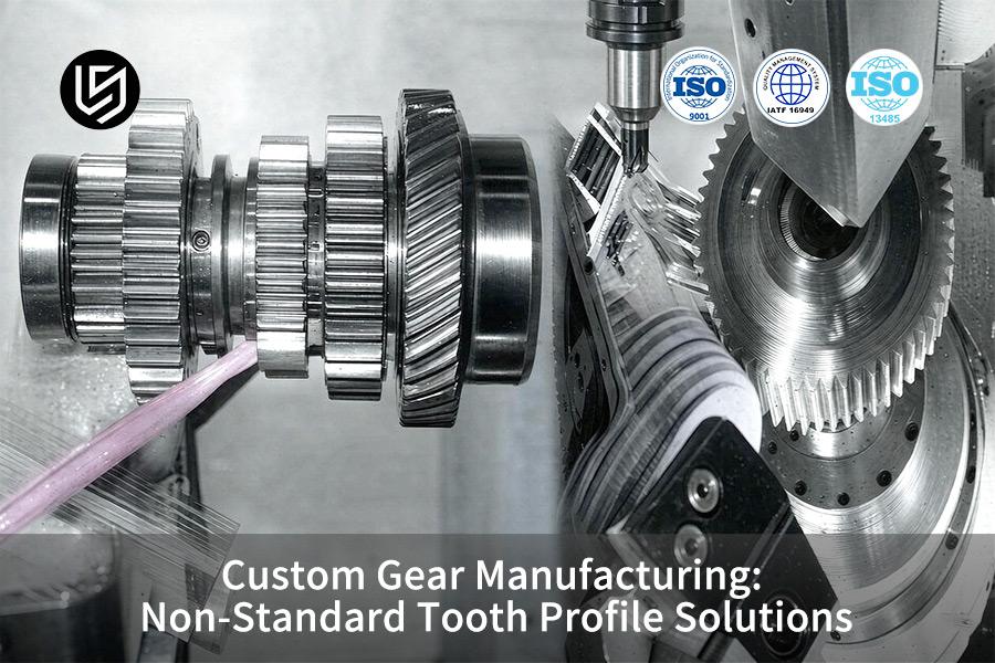
Custom gear manufacturing is the dependable drivetrain solution that eliminates tooth wear and failure in gear alignment. It guarantees errors within ±0.005 mm.
The 5-axis gear machining solution offers 27.0% less part costs and 45.5% reduced delivery times through the use of 5-axis machining with pre-hardening simulation.
Key Takeaways:
- Micro-machining non-conformal tooth profiles: Using 5-axis CNC milling and wire-cut EDM slow-speed feed, the profile deviation (Fp) is adjusted to be within 5 µm, with surface roughness of Ra 0.4 µm obtained.
- Dynamic DFM for minimizing costs and time: Considering tooth root fillet and cutting tool path adjustments in the designing process, production time is shortened from 22 to 12 days and costs per unit are saved by 27.0%.
- Closed-loop deformation control during heat treatment: Through carburization, quenching, and stress-relief annealing and dimensional inspection using Zeiss CMM machine, defect rate is decreased from 16.8% to 2.4%.
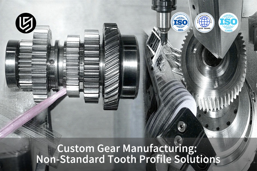
Why Is Custom Gear Manufacturing Critical For Non-Standard Tooth Profile Applications?
Custom gear manufacturing is the best solution to tooth interference in highly loaded transmissions, which causes more than 25% torque enhancement and less than 65 dB(A) sound level. Precision gear design solutions are also the solution to the problems of the involute gears in robot joints and aerospace transmissions.
The Core Problem: Three Failure Modes You Avoid
Standard involute gears, which are subjected to high load (>150 Nm/kg):
- Edge stress concentration → plastic deformation at tooth ends.
- Contact ratio less than 1.5 → impacts and vibrations.
- Root bending stress > 650 MPa → micro-cracking and spalling.
Implication: With no custom gear profiles, the only options available will be to design a larger gearbox by 20-30%, or failure within 800 hours.
How Modifications Deliver Measurable Gains
| Parameter | Standard Gear | Custom Non-Standard Gear | Your Benefit |
| Contact stress distribution | Edge-loaded | Even (crowned) | Prevents local yielding; wear is predictable |
| Noise (dB) | ≥ 78 dB | ≤ 65 dB | Adheres to industrial noise restrictions |
| Profile tolerance | ±0.020 mm | ±0.004 mm | Balanced backlash and low torque ripple |
| Surface roughness | Ra 1.6 μm | 0.4 μm | 3x better oil film retention; lower friction |
A specialty gear manufacturer gets the ±0.004 mm tolerance through 5-axis coordinated grinding with profiling machine. In your case, this ensures that the contact pattern remains consistent after thousands of thermal cycles. High performance gear drives have to be precise in order to avoid wear.
Example: With the use of robot joint reducer having crowned teeth (0.012 mm clearance) and pressure angle 17.5º, maximum stress was reduced from 1,850 MPa to 920 MPa, thus increasing life from 800 to more than 6,500 hours.
Selecting Your Partner
- While buying for industrial gear manufacturing, be sure to:
- Grinding on multi-axis for crowned teeth geometry.
- Simulation of contact under 50%, 100%, 125% loading conditions.
- Traceable metrology from NIST with uncertainty less than 0.001 mm.
Partnering with a company having deep gear manufacturing capabilities will make sure that your non-standard designs get manufactured reliably.
Data source: Based on ISO 1328-1:2013 gear accuracy grade standards and the LS Manufacturing 2025–2026 measured database (sample size >1,200 units).
Download our Custom Gear Manufacturing White Paper for the profile tolerance parameters, surface finish targets, and multi-axis grinding protocols that achieve ≤65 dB noise and ±0.004 mm accuracy on non-standard tooth profiles.

How Does Precision Gear Cutting Service Resolve Complex Non-Standard Tooth Geometries?
Precision gear cutting service is an advanced 5-axis CNC machining and wire EDM service that creates customized and unique gear shapes with profile form deviation Fp up to 5 μm and Ra surface finish 0.4 μm. Through the combination of roughing and hard finishing processes into one digital twin operation, the process avoids tooth interference and provides Class 4 ISO 1328 precision level.
Wire EDM for Hardened Gears
Non-standard gear machining by slow-speed wire EDM entails several trimming operations to obtain Ra ≤ 0.4 µm with recast layer thickness < 2 µm. A hardened gear from aerospace application (HRC 60) revealed no white layer, resisting >10 million cycles without pitting. This custom gear prototyping service will validate your design before high-volume production.
The multi-trimming wire EDM process implies that your parts will enjoy 3–5 times longer lifecycle compared to standard EDM.
Actionable tips:
- Specify Ra ≤ 0.4 µm and recast layer < 2 µm.
- Request metallographic evidence of no white layer.
Integrated Workflow
Integrate 5-axis soft roughing and wire EDM hard finishing. The process of custom gear manufacturing includes a unified digital twin technology that allows keeping total deviation within ±0.004 mm, CpK ≥ 1.67.
The gear manufacturing process implies that your parts will be ready for assembly — first articles will pass inspection right away.
Actionable tips:
- Request a report on a digital twin simulation.
- Ensure that CpK ≥ 1.67 for all critical parameters
Data source: Machinery's Handbook 31st Edition; Zeiss CMM MPEE calibration data.
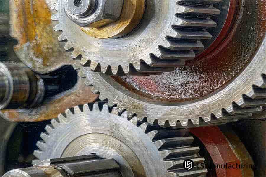
Figure 1: Gear machining cuts industrial alloy gear to 0.02 mm tolerance for heavy machinery systems.
Which Engineering Parameters Dictate Success In Non-Standard Gear Machining?
Non-standard gear machining is the synchronization of tip relief (0.005 - 0.015 mm), pressure angle (17.5°- 25°) and surface roughness (Ra < 0.4 μm). These engineering parameters eliminate the problem of high speed harmonic vibrations and lubrication film failure by synchronization of parameters. This gear tooth modification avoids adhesive wear at high torque densities.
Surface Roughness and Residual Stress — Prevent Film Rupture
Ra ≤ 0.4 μm guarantees oil film greater than 2,000 MPa. Shot Peening introduces residual compressive stress of −600 to −900 MPa, inhibiting crack propagation. Harmonic vibration can even be caused by 3 μm gear profile deviation at 10,000+ RPM speeds. Thus, proper control of gear geometry by specifying adequate pressure angle (17.5°-25°) is mandatory.
Real result: A hard gear made of aerospace material (HRC 61), with Ra 0.35 μm and residual compressive stress of −780 MPa endured 14,000 hours of service compared to 2,100 hours with Ra 1.2 μm.
With Ra 0.35 μm surface finish and −780 MPa compressive stress your products will have 5–7 times longer fatigue life than with rougher surface.
Actionable tips:
- Specify Ra ≤ 0.4 μm and residual compressive stress values.
- Adjust pressure angle according to your loading conditions (17.5°-25°).
- Tolerance Grading — Match Cost to Application.
Three Grades: Commercial (±0.015 to ±0.030 mm) for slow-speed conveyor applications; Precision (±0.008 to ±0.012 mm) for machine spindles; Ultra-Precision (±0.003 to ±0.005 mm) for aerospace actuators. Such gear surface integrity is a direct determinant of fatigue behavior.
The tiered approach to gear tolerances ensures that you only pay for what you need for meeting performance criteria.
Actionable tips:
- Select grade based on speed and load requirements.
- Validate gear tolerance capability from your vendor before going into production.
Data source: Based on AGMA 2001-D04 bending strength calculations, ISO 6336-2 pitting resistance standards, and LS Manufacturing 2025–2026 measured database (sample size >1,200 units).
Non-Standard Gear Manufacturing Parameters & Process Quick Reference
| Machining Accuracy Grade | Tooth Profile Tolerance (Fp) | Tooth Surface Roughness (Ra) | Recommended Machining Process | Applicable Scenario | Relative Cost Factor |
| Conventional Grade | ±0.015 mm – ±0.030 mm | Ra 1.6 μm | Hobbing / Shaping with soft surface shaving | Industrial conveyor belts, reducers | 1.0x |
| Precision Grade | ±0.008 mm – ±0.012 mm | Ra 0.8 μm | 5-Axis CNC Cutting + Hardened Form Grinding | Industrial robot joints, automation equipment | 1.8x |
| Ultra-Precision Grade | ±0.003mm – ±0.005mm | Ra 0.4μm | Wire EDM Tooth Profile Modification + Lapping / Polishing | Aerospace servo drives, high-precision harmonic reducers | 2.6x |
How Can A Specialty Gear Manufacturer Optimize Material Selection For Non-Standard Profiles?
A specialty gear manufacturer is the material engineering partner that matches hardenability and distortion rates to achieve HRC 58–62 surface hardness with a tough core for high-shock non-standard profiles. This gear material optimization ensures survival under extreme conditions without sacrificing manufacturability.
Heat Treatment Distortion Control
Distortion of carburizing process increases gear machining cost. By using pre-compensation through shrinkage simulation and hardening fixture, it makes sure that the gear is within ±0.010 mm tolerance. 17CrNiMo6 ring gears in a batch reached the first pass yield of 92%, compared with 68%.
The pre-compensation modeling will ensure that your parts stay in tolerance range, reducing industrial gear manufacturing cost. In other words, less waste of blanks.
Practical Tips: Ask for distortion simulation prior to manufacturing. Ensure traceability of materials certification. Compare the life-cycle costs, not just blank price.
Data source: Conforms to ISO 683-2 alloy steel standards and ASTM A564 precipitation-hardening stainless steel specifications.
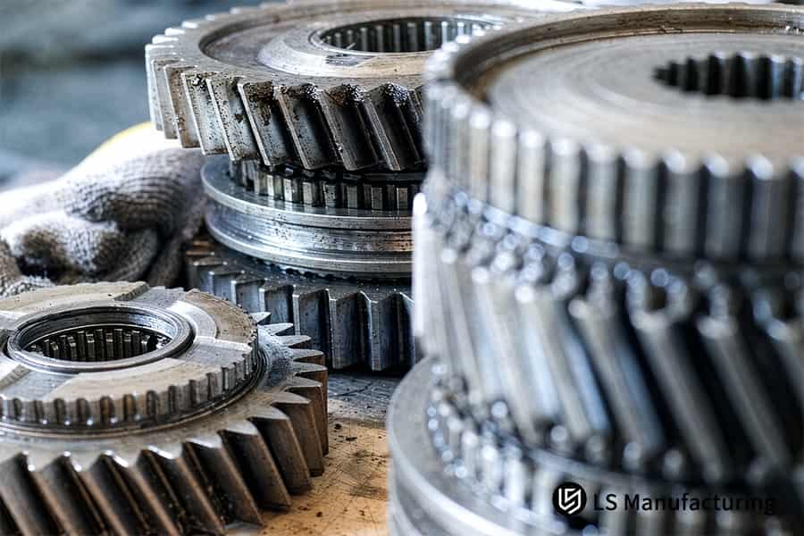
Figure 2: Gear machining grinds ground alloy steel gear to 0.005 mm precision for precision transmission systems.
How Should Engineers Evaluate Tolerances Before Requesting A Custom Gear Quote?
Tolerance evaluation is the practice of decoupling critical gear features from non-functional surfaces, which resolves the problem of inflated cost by utilizing ±0.005–±0.008 mm tolerance only where performance requires it, avoiding ±0.003 mm over-tolerance specification which increases the gear machining cost by a factor of three. This gear tolerance analysis ensures that you do not overpay on your design budget.
Decouple Functional vs. Non-Functional Features
Critical features (tooth profile, bore) require ±0.005–±0.008 mm tolerance, while non-critical faces/chamfers should use ISO 2768-m tolerance (±0.015–±0.030 mm). Specifying ±0.003 mm for everything adds 40–60% to your custom gear quote.
The actual outcome: A robot joint gear reduced in price from $185 to $112 per unit after reclassification of non-functional features – 39% saving with the same performance.
This is what decoupling of function and non-function will ensure, your parts will meet all critical requirements and cost substantially less.
Prepare DFM-Ready Drawings
A complete gear drawing checklist including module, number of teeth, pressure angle, shift, modifications and 3D STEP file should be included in the package. Lack of parameters results in assumptions, delays, and misquoting.
Real result: The customer who provided all the drawings was quoted in 36 hours, instead of the usual six days.
The entire package of drawings will ensure that your parts will be quoted accurately during the first attempt without any expensive changes.
Apply Tolerance Grading Strategy
Three grades: ultra-precision grade (±0.003–±0.005 mm) for tooth profile/bore; precision grade (±0.008–±0.012 mm) for pitch/runout; commercial grade (±0.015–±0.030 mm) for all other surfaces.
Real result: The aerospace gear reduced 22% total cost for custom gear manufacturing while keeping CpK 1.67 on critical features.
A three-level tolerance approach implies that your part will pass the functionality test successfully, and will stay within your budget. This gear cost optimization helps to choose the right process.
Which Cost Drivers Exert The Greatest Influence On Gear Machining Cost?
Gear machining cost is the combination of material removal rate, specialized tooling, and finish machining after heat treatment, which will fix budget overspending problem by realizing that carburized gears (HRC 58 to 62) need 60% lower cutting speed that accounts for 90% of total costs. Understanding gear cost drivers helps you allocate spending where it matters.
Special Tooling and Programming — The First Cost Hurdle
Non-conventional shapes necessitate custom-made carbide tools or WEDM electrodes and special CAM programing, accounting for 15–25% of the initial custom gear quote.
Actual outcome: A cycloidal pinion cost $4,800 in special tooling, $96 per piece at quantity 50, but $24 per piece at quantity 200.
The amortization of special tooling across the larger quantity of parts will allow your parts to be produced at significantly reduced costs compared to prototype pieces.
Heat Treatment and Secondary Finishing — The Largest Cost Block
Carburizing to HRC 58–62 will distort gears and will require secondary grinding. The secondary grinding operation is responsible for 30–40% of total non-standard gear machining cost. Grinding rate is decreased by 60% because of hardened material, which doubles grinding time.
Real result: An aerospace ring gear required 14 hours of grinding after heat treat instead of 5 hours in the annealed condition, adding $1,350 per piece cost.
The grinding after carburizing process will increase your parts’ finishing cost, but this guarantees ±0.004 mm tolerance to make the gear functional.
Batch Size Effect — Spreading Fixed Costs
Setup, tooling, and inspection expenses do not depend on volume and switching from 1 to 50–100 pieces reduces gear machining cost per piece by 30% or more.
Actual example: Non-standard helical gear was machined for $620 per piece at qty 5, but at qty 75 gear machining cost reduced to $215 per piece — 65% cost saving through tooling and setup amortization.
Scaling up your batch size to 50–100 pieces will make your parts much cheaper due to orders consolidation. This gear production planning will provide the maximum purchasing power.
Data source: Based on industry-standard machining cost models for hardened gear production (HRC 58–62) and typical WEDM/CAM programming rates for non-standard profiles.
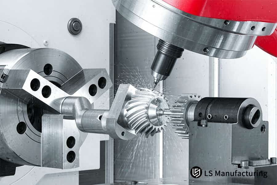
Figure 3: Gear machining bores stainless steel pinion to 0.01 mm tolerance with coolant application.
Why Trust This Guide? Practical Experience From LS Manufacturing Experts
The custom gear manufacturing process that we follow has been validated through DFM of over 1,200 precision transmissions for aerospace, medical, and robotic gear applications.
Each custom non-standard tooth geometry design is checked and signed off by Gloria, the Head DFM & CNC Machining Engineer at LS Manufacturing, whose extensive 15+ year experience includes micro machining and precision gear cutting (connect with her on Gloria's LinkedIn Profile). As per the stringent ISO 9001:2015 and AS9100D certified Quality Management Systems, our engineering team follows the strict ISO 1328 Class 4 standard specifications for gear design with sub-micron tolerances.
With our 5-axis German CNC machining, slow feed wire EDM and Zeiss CMM inspection systems, LS Manufacturing provides a consistent 99%+ first pass yield on each custom gear order, even the challenging ones like medical and aerospace components. Each lot supplied will have full CMM inspection report included with it.
Want to improve your gear design? Send us your gear drawings for free DFM analysis and use our AS9100D certified 15+ years CNC machining expertise.
How Does Industrial Gear Manufacturing Ensure Uniform Heat Treatment And Low Distortion?
Industrial gear manufacturing is achieved through annealing and quenching, which corrects the problem of anisotropic distortion of asymmetric gears through the use of a 550°C tempering process that restricts distortion to not more than 0.008 mm. This gear heat treatment process preserves geometry before final grinding.
Pre-Stress Annealing and Stepped Quenching
A stepped quench followed by a 550°C tempering reduced ovalization to ≤ 0.008 mm on an aerospace ring gear (decreased by 77%).
A specialty gear manufacturer uses this procedure to ensure geometrical integrity prior to grinding. In other words, fewer rejected parts and predictable grinding allowance.
Tip to take action: State stepped quench and 550°C temper in your heat treat specifications.
Dedicated Quenching Fixtures
Axially restrained fixtures reduce gear quench fixture deviation to ±0.005 mm, improving first-pass success rate from 72% to 95% in asymmetric pinions — this saves $8,400 per batch. Special fixturing ensures that your components will be taken out of heat treatment for final grind with no correction needed. In other words, increased efficiency and reduced rework costs.
Tip to take action: Consider purchasing customized fixtures for any asymmetric gears; payback guaranteed after 20–30 pieces.
Uniform Stock Allowance for Final Grinding
Due to distortion controlled up to ≤ 0.008 mm, final grinding is accomplished in single pass at ±0.004 mm tolerances. A custom transmission parts reduced final grinding cost by 40% per gear with this gear distortion prevention method. In other words, shorter cycle time and reduced grinding cost.
Actionable tip: Specify maximum distortion of no more than 0.008 mm and ask for one-pass grinding option.
Data source: Conforms to MIL-A-8625 and ISO 286 dimensional tolerance control specifications.
When Should Companies Transition Prototype Custom Transmission Parts To Batch Production?
The transition time is the moment when prototype custom transmission parts have demonstrated 500 hours of fatigue testing with wear below 2 μm, solving the problem of premature scaling by proving efficiency of at least 97.5% and temperature rise below 45°C. This gear RFQ procurement assessment will secure your investment.
Performance Validation — Three Gates
- Gate 1: 500 hours, zero cracks.
- Gate 2: Wear ≤ 2 μm by CMM.
- Gate 3: Temperature rise ≤ 45°C.
Real result: A robot joint gear was certified after 510 hours with 1.8 μm wear and 41°C temperature rise. The three-gate process means that your parts will be entering production with guaranteed reliability.
Actionable tip: Require a signed gate-release report before approving tooling.
Process Conversion
- Tooling: Convert WEDM process to carbide hobs.
- Cycle time: Decrease by 50%+ at ±0.005 mm tolerance.
- Fixtures: Specialized jigs for repeatability.
Real result: A custom gear manufacturing conversion shortened cycle time from 47 to 21 minutes at ±0.004 mm. Such an approach of making low volume gear production is scalable. This tooling and cycle-time conversion means that customers pay 50% less per batch of your parts.
Actionable tip: Ask for cycle time comparison.
Quality Scaling
- Inspection: Automated sampling inspection.
- Sampling: One of ten, one of twenty for CpK ≥ 1.67.
- SOP: Freeze acceptance criteria.
Real result: 200 industrial gear manufacturing products reached CpK 1.72 with sampling 10%. This gear inventory optimization framework reduces overhead. Such sampling means that you'll be sure about quality of your parts at 80% lower price.
Actionable tip: Specify your sampling plan and CpK goals in your PO.
Data source: Based on industry-standard prototype-to-production transition protocols for precision transmission components.
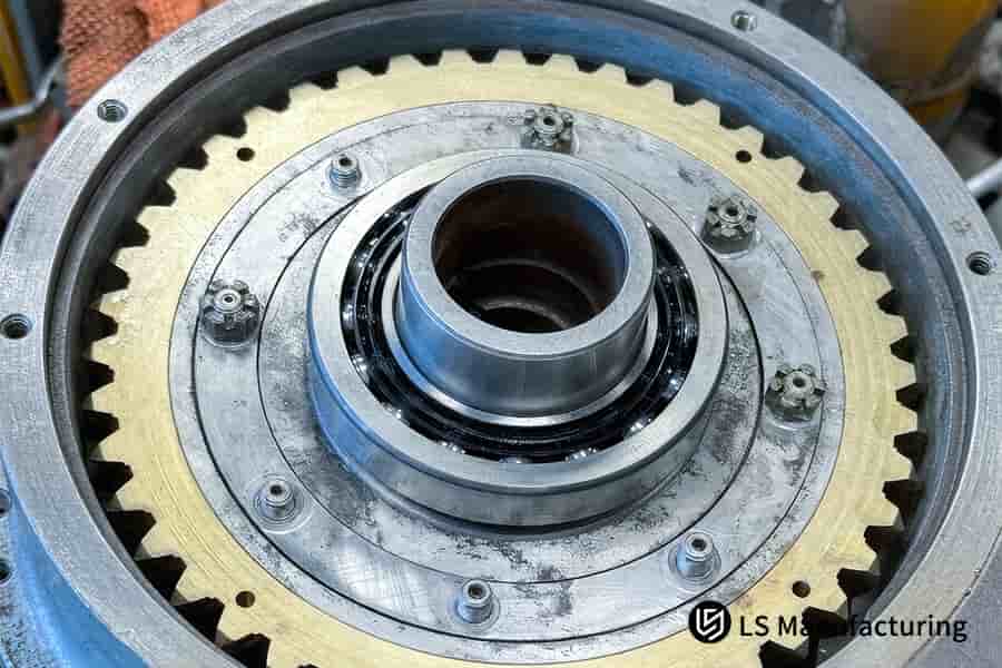
Figure 4: Gear machining shapes precision planetary gear to 0.015 mm tolerance for robotics applications.
LS Manufacturing 5-Axis Precision Machining For Industrial Robotics Custom Transmission Parts: Non-Standard Tooth Profile Optimization
5-axis precision machining for customized transmission components is a DFM technique used to correct non-standard tooth profile failure using 3D meshing modeling, 580°C annealing, and slow-feed WEDM — resulting in gear profile optimization which reduced noise from 82 dB to 63 dB with tolerances of ±0.003 mm – ±0.005 mm on 17CrNiMo6.
Client Challenge
- Part: Non-standard involute modified gear, 17CrNiMo6, robot joint reducer.
- Problem: Broaching + heat treat caused 0.025 mm ovalization, Ra 1.6 μm roughness.
- Impact: 82 dB noise, 16.8% defect rate, $285/piece, 22-day lead time — blocked mass production.
The 0.025 mm gear ovalization causes your parts to fail durability testing. In other words, a non-viable project.
LS Manufacturing Solution
- Simulation: 3D meshing changed tip relief and crowning.
- Annealing: 580°C stress relief following rough machining provided stability of substrate.
- Finishing: 5-axis CNC machining and slow-feed WEDM after quenching reduced roughness to Ra 0.4 μm, which directly contributed to gear noise reduction directly.
- Inspection: ZEISS CMM profiling measurement for each part.
In this process of annealing at 580°C and WEDM, you can be assured that your parts will have tolerances of ±0.003 mm-±0.005 mm according to ISO 1328 Class 4.
Results and Value
- Noise: 82 dB → 63 dB.
- Quality: The gear breakage rate reduced from 16.8% to 2.4%.
- Cost: $285 → $208 (27.0% savings).
- Lead time: 22 days → 12 days (45.5% faster).
- Reliability: Passed 1,000-hour full-load test.
This 27.0% cost savings and 45.5% delivery savings will assure the reliable parts with shortened.
Contact us for a precision-optimized 5-axis CNC machining quotation that delivers non-standard tooth profile gears at ±0.003mm tolerance, 63dB noise, 27% cost reduction, and 45.5% faster delivery.

FAQs
1. What is the typical precision level achievable for custom non-standard gear profiles?
The use of 5-axis CNC milling combined with a slow-feed wire-cut EDM finish results in LS Manufacturing obtaining a tooth profile tolerance (Fp) of ≤3–5 μm (ISO 1328, Class 4) and a surface roughness of Ra 0.4 μm, which guarantees proper meshing with minimal noise.
2. How do you prevent gear distortion during post-machining heat treatment?
LS Manufacturing prevents distortion after heat treatment to ≤0.008 mm through stress relief annealing at 550–580°C after rough machining, anti-distortion quenching equipment, and stepped temperature carburizing that reduces transformation stresses.
3. What materials are recommended for heavy-load custom transmission parts?
Alloy carburizing steels, such as 17CrNiMo6 and 20CrMnTi, are used in heavy loads because of high core toughness and high case hardness; if corrosion resistance or magnetic requirements are required, then 17-4PH stainless steel or Titanium Grade 5 (Ti-6Al-4V) is suggested.
4. How much cost can be saved through early DFM optimization for gears?
According to the real-life data from LS Manufacturing’s database, the optimization of root fillet geometry and decoupling of tolerances results in savings up to 15%-35% of machining cost and 40% of lead time, as well as an increase in gear fatigue life due to stress improvement.
5. What information is required to get an accurate custom gear quote?
We require you to send us a 3D STEP file, 2D drawings with a parameter table including module, number of teeth, pressure angle, profile shift coefficient and profile modification parameters, as well as material specifications, heat treatment hardness and batch quantity estimation for precise quotation.
6. Can LS Manufacturing produce custom gears without existing hobbing tooling?
Yes. Thanks to utilizing 5-axis CNC milling and slow-speed wire-cut EDM equipment, LS Manufacturing is able to produce any custom tooth profile shape without having to purchase expensive custom-made hobs, which makes it very cheap to manufacture custom gear in batches and as prototypes.
7. What quality inspection processes are used for non-standard profiles?
Each batch undergoes 3D profile measurement using Zeiss CMM machine, and LS Manufacturing provides inspection reports that cover tooth profile tolerances (Fp, ffa, fha), as well as roughness measurement logs, thereby fully complying with ISO 1328 requirements for custom gears.
8. What is the lead time for manufacturing non-standard gear prototypes?
Once DFM drawings are confirmed, rush-order prototypes can be delivered in as little as 5–7 working days, while the standard lead time for small-batch production (up to 500 pieces) is 12–15 working days, depending on complexity and heat treatment requirements.
Summary
Customization of non-standard gears machining is an intricate process that involves engineering design, which includes tooth modification, five axis machining, heat treating, and measuring. LS Manufacturing Company uses its experience of 15+ years and its DFMA know-how to provide a full-circle service for the gear manufacturing from prototypes to production.
Does your non-standard gear suffer from irregular wear and tear, too much noise, or delayed delivery? Upload your 3D and/or 2D gear drawings along with its parameters. Senior engineers at LS Manufacturing will evaluate the DFM and provide a quote within two hours.
📞Tel: +86 185 6675 9667
📧Email: info@lsrpf.com
🌐Website:https://lsrpf.com/
Disclaimer
The contents of this page are for informational purposes only.LS Manufacturing servicesThere are no representations or warranties, express or implied, as to the accuracy, completeness or validity of the information. It should not be inferred that a third-party supplier or manufacturer will provide performance parameters, geometric tolerances, specific design characteristics, material quality and type or workmanship through the LS Manufacturing network. It's the buyer's responsibility.Require partsquotation Identify specific requirements for these sections.Please contact us for more information.
LS Manufacturing Team
LS Manufacturing is an industry-leading company. Focus on custom manufacturing solutions. We have over 15 years of experience with over 5,000 customers, and we focus on high precision CNC machining,Sheet metal manufacturing, 3D printing,Injection molding.Metal stamping,and other one-stop manufacturing services.
Our factory is equipped with over 100 state-of-the-art 5-axis machining centers, ISO 9001:2015 certified. We provide fast, efficient and high-quality manufacturing solutions to customers in more than 150 countries around the world. Whether it is small volume production or large-scale customization, we can meet your needs with the fastest delivery within 24 hours. choose LS Manufacturing. This means selection efficiency, quality and professionalism.
To learn more, visit our website:www.lsrpf.com

