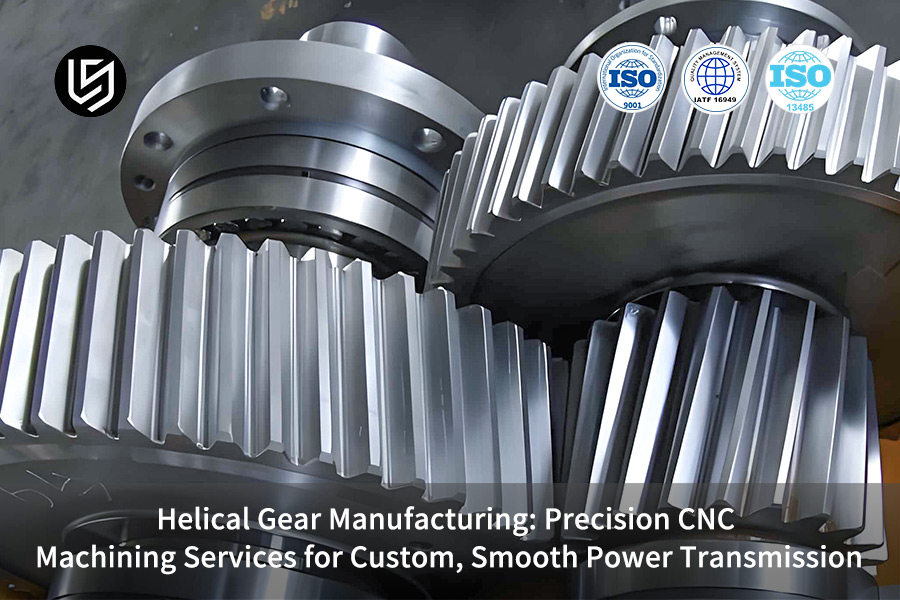
Helical gear manufacturing often fails to meet NVH and durability targets in demanding applications because suppliers treat helical gears merely as angled spur gears. We do this by integrating design, precision modification of the tooth surface for specific load spectra, and core process control, which is a way of directly addressing most of the problems such as excessive noise, premature pitting, and the compromising of weight-performance, thus turning theoretical specifications into a quiet, running operation of high reliability.
Our solution uses a 15 years' top-tier projects proprietary database to be able to give an exact, numerical expansion of the helix angle optimization, micro-geometry correction and the choice of the material. Thus, the systematic reduction of the transmission error is made and batch consistency is assured which is the way of performance and life expectancy beyond the theoretical ones of the gears in the actual operating conditions.
Helical Gear Manufacturing: Quick-Reference Guide
| Focus Area | Key Consideration |
| Design Complexity | Helical gears require accurate setting of helix angle, lead, and tooth profile in order to transmit torque smoothly and generate low noise. |
| Critical Challenge | The heat treatment-generated distortions should be kept to a minimum so that the final gear geometry is not compromised and the required hardness is achieved. |
| Common Compromise | When the tooth surface is too hard for wear resistance, and the core is too soft for strength, both are not optimally utilized. |
| Process Foundation | The integration of process steps from soft machining, through heat treatment, to final hard finishing (grinding/honing) is essential to the success. |
| Our Technical Approach | We rely on predictive modeling for distortion compensation and are equipped with a state-of-the-art gear grinding for the best surface finish and accuracy. |
| Quality Assurance | 100% inspection of critical parameters (profile, lead, pitch) via gear measurement centers ensures consistent performance. |
| Performance Result | Gears produced are capable of withstanding high power density, they operate smoothly and quietly, and have a long service life even when subjected to tough conditions. |
| Reliability Outcome | By ensuring precise tooth contact patterns and optimal load distribution, the performance and durability of the product can be achieved predictably. |
It is a core part of our challenge that we really understand and solve the main issues of manufacturing high-performance helical gears: controlling distortion, achieving precise geometry, and balancing material properties. Through our integrated process, your gears will not only be able to deliver smooth, quiet, reliable power transmission but also have a longer life, thus eliminating premature failure and system downtime.
Why Trust This Guide? Practical Experience From LS Manufacturing Experts
There is an abundance of helical gear manufacturing articles available; however, our article is a first, hand account from the workshop floor, where precision is the main focus daily under the strictest Occupational Safety and Health Administration (OSHA), compliant conditions. Our main enemy is noise, wear, and weight, thus turning complex specifications into reliable, custom solutions for smooth power transmission through applied, not merely, theoretical, knowledge.
Our components play a vital role in aerospace, EV, and robotics, where failure is simply not an option. Every micro-modification and material selection has been a lesson in delivering actual parts and aligning the processes to US Environmental Protection Agency (US EPA) standards, thus ensuring that performance is achieved in a responsible and sustainable way for the long term.
Every single piece of advice here has been derived from success as well as costly failures in machining and heat-treating gears. We disclose this tried, and true practical know how in order that you might not make the same mistakes as we did in the beginning. This is the exact level of proficiency we employ when we manufacture custom gears capable of genuinely smooth and long, lasting power transmission.
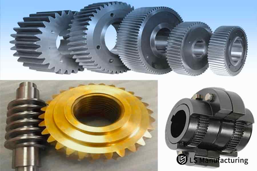
Figure 1: Machining high-tolerance alloy steel helical gears for heavy machinery and industrial power transmission services.
How To Scientifically Define Helical Gear Parameters To Achieve The Optimal Balance Between Noise, Efficiency And Strength?
Finding the best compromise among noise, efficiency, and strength in helical gear design is a tough engineering challenge. Naturally, it requires a methodical, application-focused parameter optimization wherein advancing one attribute almost always negatively affects another. Here we explain our approach to operating within these limitations to provide reliable power transmission:
Strategic Helix Angle Selection for NVH and Load Management
The helix angle (β) is a major factor in deciding the noise and the bearing loads. A higher β means not only a higher overlap ratio for quieter, SPM (smooth power transmission gears) but also larger axial forces at the same time. A single EV reducer cannot be a case of solely maximizing β. We have recognized that a 15° helix angle is an excellent compromise, which allows a major NVH improvement on the one hand, and on the other, the axial loads on the bearings given are at the level that these bearings can be expected to handle, thus, the system lifetime is directly extended.
Adapting Pressure Angle for Enhanced Bending Strength
Normally the pressure angle (αₙ) in the gear tooth plane is 20° but it is not a strict rule. When it was a high torque powertrain, custom helical gears required very strong tooth roots. We very carefully increased αₙ to 22.5° which not only made the tooth base stronger, a key factor for durable helical gears, but also brought about a slight reduction in contact ratio which was more than compensated by the helix angle optimization and, hence, a calculated trade, off in the minor side effect of the lowered contact ratio.
Employing Profile Shift to Equalize Durability
Profile shift coefficients (x₁, x₂) are probably the single largest factor influencing the durability balance of gears. Taking a pair of gears with a high transmission ratio as an example, the small pinion is most likely to be the weakest part of the system. We shifted the pinion up while at the same time, the gear was shifted down. As a result, the relative sliding speeds as well as the bending stresses at the roots of the two components were matched, which led to a huge increase in the fatigue life and reliability of the system.
Integrated Design Validation Through Scenario Modeling
Single, point design is not our final product but several iterations of a single-point design. We illustrate parameter interactions in full and provide the clients with 2-3 optimal scenarios. Scenario A, for instance, could be entirely dedicated to reducing the vehicles cabin noise for the purposes of comfort while Scenario B focuses on torque density. The direct, data-driven comparison allows fusings the decision-making power issue, among others, your very specific precision helical gears.
This well-organized, trade-off-centric methodology reflects our profound technical understanding. We go beyond just offering specs; we deliver verified design intelligence that can effectively solve the main dilemmas of gear noise, efficiency, and strength, thus providing rugged, application - optimized gear systems right from the start.

How To Ensure The Consistency Of Tooth Direction Accuracy And Helix Line When CNC Machining Helical Gears?
Successfully meeting the requirements for exact tooth trace alignment and constant helix geometry is a necessary step to obtain quiet, efficient, and precision helical gears. The presentation reviews the specific target controls required to maintain rigorous gear accuracy control during bulk production, which, in turn, significantly affects the overall transmission performance.
| Control Dimension | Key Method & Quantified Target |
| Machine Tool Precision | Synchronize B-axis (rotation) and Z-axis (feed) with ≤ ±5 arcsec error to limit lead deviation to <0.005mm/100mm. |
| Tooling Setup & Compensation | Utilize laser tool setters for precise cutter installation and carry out in-process measurement for real, time wear compensation. |
| Thermal Stability Management | Adopt constant, temperature oil cooling to keep tool/workpiece within ±1°C, thus avoiding thermal drift. |
| Resulting Quality Standard | Control total tooth trace error (Fβ) within DIN grade 6 all the time for batch-produced CNC helical gear machining. |
This combined approach tackles the root causes of helix deviation - mechanical, tooling, and thermal. We control these variables with quantified rigor to fundamentally challenge the production of durable helical gears with predictable high-performance meshing characteristics for demanding applications.
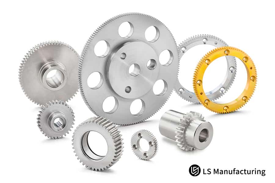
Figure 2: Fabricating high-tolerance alloy steel bevel and helical gears for precision power transmission systems.
Why Are Tooth Profile And Tooth Direction Modification Key To Solving The Squealing And Impact Of Helical Gears?
Under theoretical perfect tooth geometry, gear teeth fail when subjected to real, world loads which cause deflection, transmission error (TE), and concentrated edge contact. As a result, the gears produce whining noise and are prone to shock loading. Gear modification is the designed method of precisely changing the tooth shape to match the compensating effects, thus operation is smooth and the gear has a long life. Standard gear modification is a step that goes beyond our methodology.
Profile Modification to Mitigate Entry/Exit Shock
Standard involute teeth clash at the tips and roots during engagement under load. We deliver a focused tip and root relief (5-10 μm) to these localities. Such a subtle and precise gear finishing creates the clearance for a smooth tooth entry and exit capable of reducing the impact forces that directly cause audible gear whine in the assembled transmissions.
Lead Crowning to Ensure Uniform Load Distribution
Shaft deflection and misalignment lead to overload at the gear ends. We counteract this problem by making a very accurate barrel shape, or crown, on the tooth face (e.g., 0.015mm). This advanced gear modification allows contact to move to the center when the gear is loaded, thereby stress is equally distributed over the entire face width and thus, early wear and noise by uneven contact are avoided.
Load-Spectrum Adaptive Optimization for Application-Specific Quietness
We go beyond traditional alterations by adapting them to your operation profile. For a case of helical gear manufacturing for a wind turbine which mainly works at partial load, we simulated noise level over the whole load range. The optimal modification curve resulted in the lowest noise at the 60-80% load range that is a true 4 dB noise reduction at the most frequent operating condition.
This methodical, forecasting approach to precision gear engineering makes gear modifications no longer a generic correction but rather a performance-defining attribute. We do not only make high-performance helical gears quieter but also increase their life through optimized load management which is perfectly matched to the exact demands of your application.
Deformation Pattern Of Helical Gears After Heat Treatment? Accuracy Compensation And Repair?
Attaining micron-level accuracy in precision gear manufacturing is largely hindered by heat treatment distortions that, while being predictable, are inherently complex. LS Manufacturing through its well, structured approach converts this problem into a controllable, compensable factor, thus guaranteeing part conformity in the end.
Process Optimization for Minimal Distortion
- Core Technology: Employing vacuum Low-Pressure Carburizing (LPC) with high-pressure gas quenching.
- Result: A stable helical gear manufacturing baseline is established with up to 50% less distortion compared to oil quenching.
- Control: Meticulous regulation of thermal and phase transformation gradients.
Data-Driven Pre-Compensation
- Prediction Engine: Leveraging a proprietary material-geometry-process database.
- Action: Incorporating anti-deformation offsets during soft machining (e.g., pre-adjusting helix angle).
- Outcome: Heat treatment distortion control vectors are neutralized in advance by active countermeasures.
Final Micro-Correction
- Necessity: Essential for helical gear accuracy of DIN 5+ grade.
- Solution: Stock removal with high precision through CNC form gear grinding.
- Final State: Removes nanoscale form errors and attains Ra ≤ 0.4 μm surface finish for peak performance.
This paper describes a closed-lloop system that combines predictive compensation with precision finishing, so the distortion issue is not a problem but a controllable process variable. We handle the distortion problem by the following steps: firstly, the process is controlled; secondly, the error is pre-corrected; and finally, micro-grinding to the specification, thus producing reliable, high-integrity helical gear solutions that always satisfy the most demanding performance tests.
What Are The Actual Performance And Cost Comparison Data For Helical Gears, Spur Gears, And Herringbone Gears?
Choosing the right type of gear needs quantitative data rather than qualitative claims. This paper presents a brief factual comparison of the main performance and cost parameters of the helical gear vs spur gear and herringbone designs, which are based on the same module, material, and quality grades, to facilitate unbiased engineering choices.
| Characteristic | Helical Gear (β=15°) | Spur Gear | Herringbone Gear |
| Contact Ratio | High (2.2-2.8), which is great for the smooth engagement. | Low (1.4-1.8), so the forces are transferred more discretely. | Extremely high as a result of the dual, opposing helical gear teeth. |
| Noise & Smoothness | Excellent, typically 5-10 dB quieter than spur gears. | Moderate, suitable for less critical applications. | Excellent, with theoretically self-balanced axial forces. |
| Axial Thrust | Present, requiring appropriate thrust bearing support. | None, simplifying bearing arrangements. | Nominally zero, ideal for very high-load configurations. |
| Relative Manufacturing Cost | Baseline (1.0x), offering a balanced cost-performance analysis. | Lower (0.7 – 0.8x), most economical for simple drives | High (1.5 – 2.0x), due to complex helical gear machining. |
| Primary Application | General high-speed, precision power transmission gears. | Low-speed or spatially constrained designs. | Heavy-duty, ultra-high-torque machinery. |
The data points to the fact that precision helical gears are the best choice for most industrial drives as they offer a combination of smooth operation, strength, and cost. Our cost-performance analysis helps clients to select products objectively, thus, moving away from theoretical arguments to practical, data-driven designs. This method resolves the principal issue of gear type selection to meet noise, load, and budget targets specifically with confidence.
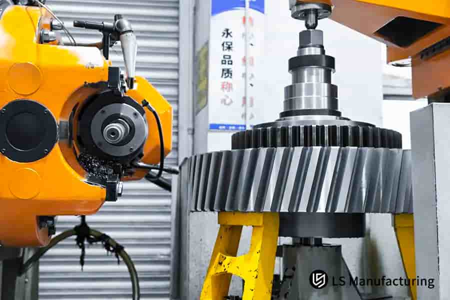
Figure 3: Machining high-tolerance alloy steel custom helical gears for industrial machinery and smooth power transmission.
LS Manufacturing New Energy Vehicle Industry: Electric Drive Reducer Helical Gear NVH Extreme Optimization Project
This LS Manufacturing EV case study elaborates on how we eliminated the noise of the gear whine in a high, end electric vehicle's drivetrain by moving beyond the usual adjustments and thus, removing the real cause:
Client Challenge
An EV manufacturer on the top of the market was dealing with the problem of gear whine (>70 dB SPL) caused by its reducer's main precision helical gears (20CrMnTiH, DIN 6). Vehicle acoustic certification and model launch were both threatened as a result of the failure of the initial macro-geometry changes. The challenge was to provide a quick NVH solution without any compromise on transmission efficiency or durability.
LS Manufacturing Solution
We conducted an exhaustive 3D topographical study on a gear coordinate measuring machine and correlated the results with NVH tests. It pinpointed mid, frequency waviness on the tooth flanks as the main source of excitation. Our custom helical gear solution brought in a targeted micro-topography alteration which, through a controlled faceting wheel dressing process, removed only <2μm of material at very specific phase zones suppressing the waviness at the very source.
Results and Value
The specialized whine was completely removed after the modification resulting in a 12 dB reduction at the critical band. The overall system NVH reached top-class standards which allowed a very successful vehicle launch. The gear NVH optimization we provided to this project resulted in a reliable performance and a real competitive advantage for the client, thus demonstrating our ability to handle complex transmission noise issues.
This case is a showcase of our methodical helical gear solutions in meeting extreme NVH targets. We are able to out of the blue pinpoint and fix the source of excitation at the level of micro-topography altogether offering precision engineering which directly leads to superior in-vehicle acoustic quality and quicker problem, solving for demanding EV applications.
Struggling with gear noise from transmission error? Contact us for a targeted NVH solution.

How To Assess The Actual Manufacturing And Testing Capabilities Of A Helical Gear Supplier?
Evaluating a helical gear manufacturer means more than just listing their basic equipment. It mounts a demand on their knowledge of the manufacturing process and the depth of their quality assurance to be the criteria of the evaluation. A thorough assessment reveals an aspect of their character which is the certainty of regularly delivering high-performance precision helical gears sets.
Inspection and Metrology Capability
- Core Equipment: Check that a center for dedicated gear measurements is used to give a full topography and not just CMMs for basic dimensions.
- Data Transparency: Request real inspection reports indicating Fα, Fβ, and cumulative pitch deviations.Demand actual inspection reports showing Fα, Fβ, and cumulative pitch deviations.
Process Control and Consistency
- Statistical Proof: Examine SPC charts of the critical features; a CpK ≥ 1.67 is a proof of the process being in control over time.
- Gear Inspection Rigor: Find out if it is a standard procedure to do a 100% inspection of the critical feature or a good statistical sampling is used.
Engineering and Customization Competence
- Modification Mastery: Confirm team software for creating and implementing lead and profile adjustments.
- Core Process Control: Review command over heat treatment and finishing (e.g., precision grinding) to accomplish desired microstructure and geometry.
This systematic supplier capability assessment framework that we confirm by sharing our own templated reports and process data solves the key client challenge of de-risking helical gear sourcing. It substitutes subjective statements with objective facts, thus making sure your selected partner has the proven, data-supported capability to deliver a reliable custom helical gear performance.
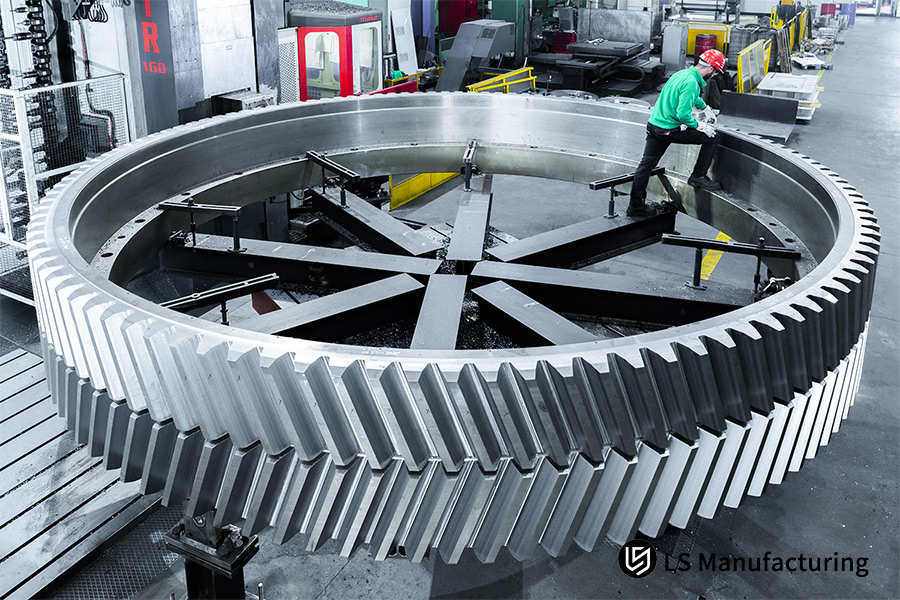
Figure 4: Inspecting a high-tolerance alloy steel helical gear for industrial power transmission systems.
Why Is It Crucial To Choose A Single Helical Gear Supplier From Prototype To Mass Production?
Splitting the prototype and production suppliers for precision helical gear entails considerable technical risk since the component's performance-defining DNA is set during the initial development. A single-source, one-stop solution from a capable helical gear manufacturer guarantees that this vital process knowledge is retained and scaled smoothly.
Prototype Phase Defines Performance DNA
The prototype step is the last step of the unique helical gear design. It involves micro-geometry adjustments, defining specific heat-treatment and surface finish targets. They are not merely blueprints but a formalized set of production instructions. We create this base through repeated testing, determining the exact parameters that give us the required NVH, efficiency, and durability results from the first sample.
The High Cost of Process Knowledge Transfer
Changing suppliers for production results in the loss of tacit know-how in helical gear cutting services and process control. The new manufacturer has to decode the specifications, which most of the time requires expensive and time-consuming re-iteration to match performance, without a guarantee of replicating the original gear's behavior. This gap directly threatens program timelines and brings unexpected quality variances in the final products.
Ensuring Seamless Scalability and Consistency
Our integrated approach ensures that the upgraded prototype process is the starting point for mass production. The same people, machinery, and tightly controlled process parameters that were involved in the development phase are directly scaled up, thus ensuring that every gear produced is an exact copy of the verified prototype. This way, requalification cycles are avoided and the reliability necessary for the most demanding power transmission gears is delivered.
The methodology that puts a focus on smooth prototype to production extension solves the primary issue of keeping performance at volume. It gives clients a de, risked, fast, track option to market by performance validation at the prototype level, which is exactly what is delivered in every production unit.
FAQs
1. What is the minimum order quantity (MOQ) for a pair of helical gears?
For standard materials small-batch trial production MOQ is typically 10-50 pieces. The mass production MOQ is subject to the complexity of the gear and thus generally ranges between 300-500 pieces, to allow for the economic amortization of mold and tooling costs.
2. What is the typical lead time for helical gears?
The lead time for a sample of gears with the processes already in place is 4-6 weeks (which includes design confirmation, machining, heat treatment, and testing). The lead time for mass production will vary depending on the quantity and be more.
3. What is the highest precision grade you can achieve?
By means of gear machining, we can continuously achieve DIN 5 precision, with the highest being DIN 3 (for very demanding applications like aerospace). For regular industrial applications, DIN 6-7 is advised for the best balance of performance and cost.
4. How do you ensure gear noise consistency in mass production?
We achieve this by tightly controlling the consistency of the "Transmission Error (TE) spectrum". Each batch of sampled gear pairs is subjected to TE testing on a dedicated meshing testing machine to make sure the fluctuation is within the limit of the acceptable one, thus securing the NVH performance.
5. Do you provide vibration and noise test reports for the gears?
Yes. For critical projects, as an extra, we can offer vibration testing for the single gears, or if you prefer, we can also carry out the mating meshing noise testing on our testing platform and provide a spectrum analysis report.
6. What lightweight solutions are available if my application is very weight-sensitive?
Keeping the strength the same, we can use topology optimization to create the shape of the gear web structure, or use high-strength lightweight materials (e.g., high-performance carburized steel), thereby achieving a weight reduction of 15-30% at the same load.
7. My old gears are worn; can you perform mapping and replication?
Yes. We are geared to offer you professional gear reverse engineering services. With the help of precise measurement, material analysis and failure assessment, we can simply replicate the gears. At the same time, we can also determine the reasons for the failure of the original gears and suggest the best solution for the new gears.
8. How do I start my helical gear project?
Kindly provide your transmission specifications (speed, torque, speed ratio, space constraints, noise targets) or just give the gear drawings. Our engineering team will review the specifications to provide a detailed custom gear quotation and get back to you with a preliminary solution within 48 hours.
Summary
The production of high-precision helical gears is definitely not a walk in the park but rather a closed loop of interaction among design science, materials engineering, precision manufacturing, and metrology. Besides dimensional accuracy, it aims at smoothness, quietness, and reliability of the final transmission system. Partners with expertise in this domain are the carriers of the core risks of transmission systems. Working with them then implies having a performance edge and market recognition for your product.
Send your transmission requirements or gear drawings to LS Manufacturing. Within 48 hours, our gear specialists will issue a complimentary "Preliminary Feasibility Analysis Report on Helical Gear Design and Manufacturing", which will cover suggestions on key parameters, highlight possible risk areas, and give you different optimization routes among other things, essentially equipping your venture with solid engineering knowledge right from the start.
Achieve whisper-quiet and efficient power transmission with our precision custom helical gear manufacturing services.
📞Tel: +86 185 6675 9667
📧Email: info@lsrpf.com
🌐Website: https://lsrpf.com/
Disclaimer
The contents of this page are for informational purposes only. LS Manufacturing services There are no representations or warranties, express or implied, as to the accuracy, completeness or validity of the information. It should not be inferred that a third-party supplier or manufacturer will provide performance parameters, geometric tolerances, specific design characteristics, material quality and type or workmanship through the LS Manufacturing network. It's the buyer's responsibility. Require parts quotation Identify specific requirements for these sections.Please contact us for more information.
LS Manufacturing Team
LS Manufacturing is an industry-leading company. Focus on custom manufacturing solutions. We have over 20 years of experience with over 5,000 customers, and we focus on high precision CNC machining, Sheet metal manufacturing, 3D printing, Injection molding. Metal stamping,and other one-stop manufacturing services.
Our factory is equipped with over 100 state-of-the-art 5-axis machining centers, ISO 9001:2015 certified. We provide fast, efficient and high-quality manufacturing solutions to customers in more than 150 countries around the world. Whether it is small volume production or large-scale customization, we can meet your needs with the fastest delivery within 24 hours. choose LS Manufacturing. This means selection efficiency, quality and professionalism.
To learn more, visit our website:www.lsrpf.com.