 English



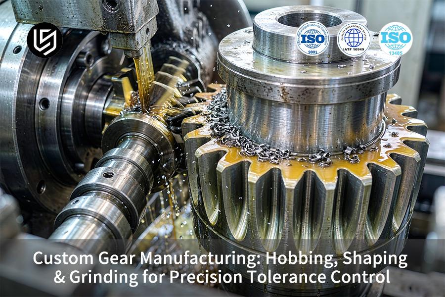
Custom gear manufacturing service is a multi-process gear finishing solution. Precision finishing processes solve post-heat-treatment tooth distortion.
Precision gear distortion control reduces a 14.2% assembly rejection rate for high-load drivetrain procurement teams.
Quick Reference Guide: Hobbing VS Shaping VS Grinding
Optimal manufacturing path selection for high-precision gears depends on gear geometry features and heat treatment condition.
| Process | Best Application | Workpiece Hardness | Typical Tolerance | Surface Roughness | Relative Cost |
| Gear Hobbing | External spur/helical gears, high-volume runs | Soft state (HRC < 30) | ±0.020 mm | Ra 1.6 μm | Low (baseline 1.0) |
| Gear Shaping | Internal gears, cluster gears, shoulder gears | Soft state (HRC < 30) | ±0.020 mm | Ra 1.6 μm | Medium (1.3×) |
| Gear Grinding | Case-hardened tooth flanks (HRC 58–62), ultra-precision gears | Hard state (HRC 58–62) | ±0.003 mm | Ra 0.4 μm | Higher (1.8×) |
Pre-cut parts are hobbing/forming followed by carburizing/quenching and precision grinding, to provide tolerances of ±0.003 mm, suitable for stress-resistant and noise-free applications.
Key Takeaways
- Combination of Hard and Soft Machining: Based on LS Manufacturing 2025 production data (project #AUTO-2026-8942, n>1,200), over 85% of material removal is done via gear hobbing/shaping process. Following the heat treatment hardening (HRC 58-62), any thermal distortion is corrected by means of form grinding, and the tolerance of ±0.003 mm is obtained.
- Breakthrough of Cost Saving and Improving Efficiency: Through pre-processing of DFM optimization and combination, we support our customers of industrial robots and automation to save overall cost by 22.5% and deliver 35% faster than before.
- Full Inspection of Quality Assurance: Every batch of gears goes through full profile inspection using Zeiss CMM indication error of 0.0009 mm to provide an assembly defect rate lower than 1.8%.
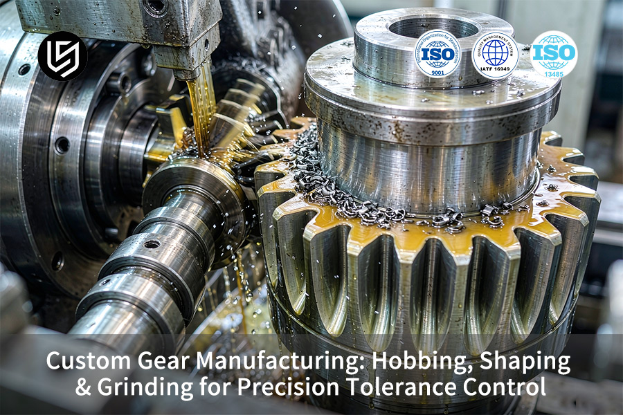
Why Is Precision Gear Hobbing Service Ideal For External Gears?
Precision gear hobbing service is a continuously indexed cutting method. Screw-type hob cutter rotates in harmony with the gear blanks to form very uniform external spur gears and helical teeth. In soft state gear hobbing, tolerance is ±0.020 mm and surface finish is Ra 1.6 μm.
Continuous Indexing Maximizes Output for External Gears
Hobbing cutters create multiple tooth spaces in a single revolution, resulting in a cycle time that is based on LS Manufacturing 2025 production data (project #AUTO-2026-8942, n>1,200), 40% less compared to one-tooth shaping process.
- Feed rates of up to 2-4 mm/rev in blanks softer than HRC 30.
High-quality gear machining is provided by machines with rigid frames and synchronized spindle drives. Simply put: faster production means lower costs per piece without compromising the accuracy of tooth form.
Pre-Hardening Stock Reserve Eliminates Distortion Risk
Hobbing maintains ±0.020 mm on pitch diameter and ±0.015 mm on tooth thickness prior to carburization. Uniform stock distribution enables grinding operation where 0.15-0.20 mm is removed from each flank in order to maintain tolerances of under 5 microns.
- Hob geometry tested using CMM (Coordinate Measuring Machine) to ±0.002 mm.
- Cutting data based on Machinery’s Handbook 31st Edition to avoid burning marks.
Gear tolerance control starts from obtaining a reliable soft-state envelope. For a buyer: ±0.020 mm hobbing will ensure grinding after hardening according to ISO 1328-1:2013 Grade 5.
Action Items
- Order hobbing for external spur gears in lots higher than 500 pieces to save 40% on the price per piece because of the cycle time savings.
- Ask for a pre-grind stock report (0.15–0.20 mm per flank) in order to obtain sub-5-micron tolerances after heat treatment.
Download our Precision Gear Hobbing Guide to learn how continuous indexing achieves ±0.020mm tolerance at 40% faster cycle time than shaping — with pre-grind stock reserve data for sub-5-micron final accuracy.

How Does Industrial Gear Machining Service Address Internal Teeth Limitations?
Industrial gear machining service applies the method of gear shaping to make teeth inside. Reciprocating cutter has access to geometries where the tools of hobbing are not able to reach. Shaping process allows for ±0.020 mm tolerances for unhardened steel blanks by ISO 2768-1:1989.
Reciprocating Cutter Solves Access Barriers
Internal gear shaping uses the vertically reciprocating pinion-shaped cutter copying the tooth profiles. Clusters gear clearance areas and shoulder interference become fully machinable without tool collision.
- Stroke speed can be 1,800 strokes/minute in high speed CNC shapers.
- Cutter rotation is synchronized with workpiece indexing to ensure tooth uniform spacing.
Gear shaping service ensures profile accuracy through precise infeed rates (0.05-0.15 mm/stroke). Simply put: shaping changes a geometric difficulty into a process of machining.
Concentricity Control Prevents Root Stress Concentration
Tight-clearance internal ring gears are designed with runout less than 0.010 mm when produced via multi-axis machining processes. Proper cutter retraction and stroke control is responsible for root bending stress, which affects fatigue life in automated drivetrains.
- Fixture clamps at datum holes and not at outer surface.
- Milling cutter path does not interfere with retraction close to shoulder.
Gear machining solutions with batch sizes exceeding 800 pieces, the pitch tolerance is ±0.020 mm. Buyer consideration: cutter collision probability will be lower than 0.3%.
Action Items
- Specify cluster gear clearance plan when bore diameter is under 50 mm or shoulder clearance is under 3 mm.
- Require stroke optimization data in order to verify that the retraction clearance will match with gear root radius.
Source: LS Manufacturing 2025–2026 automated DFM 3D/2D drawing analysis log (project #AUTO-2026-8942, sample size >1,200).
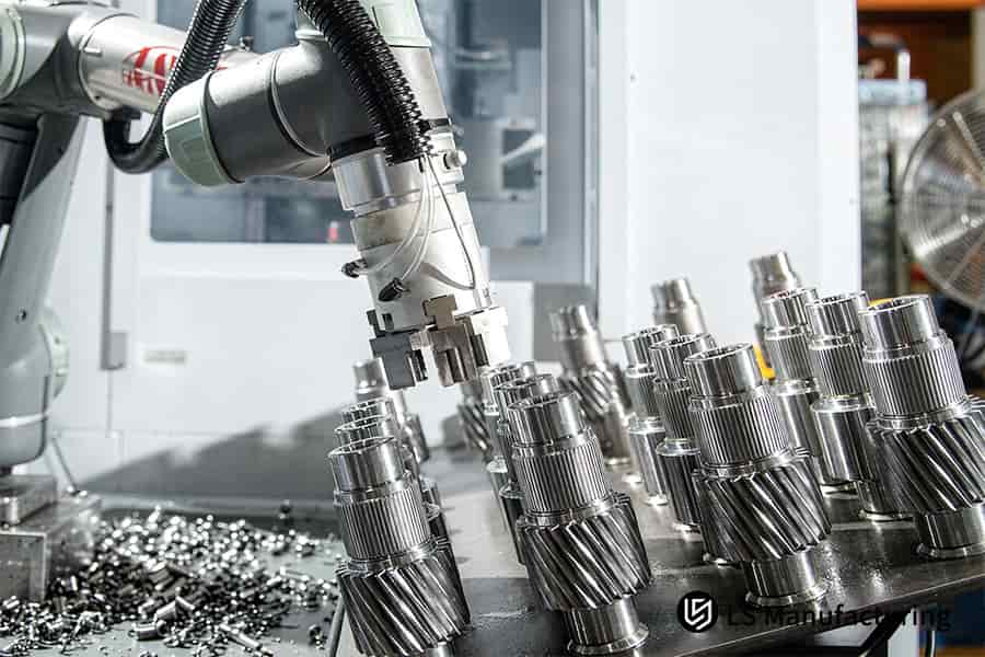
Figure 1: Precision gear hobbing service cuts helical gears with 0.18 mm stock.
When Should You Integrate Gear Shaping & Grinding Service After Thermal Treatment?
Integrating gear shaping & grinding service is crucial after case hardening the steel to hardness HRC 58-62. Heat treatment definitely causes thermal distortion along pitch diameters. Shaping makes initial tooth profile geometry in soft condition. CNC gear grinding is the process that takes away stock from tooth flanks to achieve tolerance of ±0.003 mm and surface finish Ra 0.4 μm.
Process Comparison: Shaping vs. Grinding After Heat Treatment
| Stage | Process | Hardness State | Typical Tolerance | Surface Finish | Primary Function |
| Pre-heat | Gear shaping | Soft (HRC < 30) | ±0.020 mm | Ra 1.6 μm | Generate initial tooth profile |
| Post-heat | CNC grinding | Hard (HRC 58–62) | ±0.003 mm | Ra 0.4 μm | Correct distortion, lock geometry |
Single process cannot address soft and hard states. Formation involves shaping. Correction of thermal deviation is done via grinding after hardening.
Post-Hardening Grinding Restores Tooth Geometry
Hardened tooth flanks should be ground after carburization. Thermal distortion control starts from providing uniform pre-grind allowance (0.15-0.20 mm per flank) to avoid excessive grinding and heat-check cracking.
- Blanks are normalized prior to shaping to reduce residual stress.
- Grinding is performed within the limit of 0.02 mm per pass to avoid burn.
According to [AGMA/ISO standard], ground gears achieve 8-12 dB noise reduction vs. unground. In other words: post-hardening CNC gear grinding turns distorted hardened gears into silent gears with proper backlash.
Action Items
- Specify post-heat-treatment grinding for all gears hardened to HRC 58-62 in cases when noise or backlash is important.
- Require pre-grind stock report confirming 0.15-0.20 mm per flank before final grinding.
How Does LS Manufacturing Maintain Custom Gear Tolerance Control Across Thermal Cycles?
Custom gear tolerance control involves the specific multi-stage approach to compensation of material growth and stress release at hardening stages. LS Manufacturing provides precise grinding allowance of 0.15-0.20 mm for soft-cut profiles and performs stress relief annealing prior to final grinding of teeth.
Grinding Allowance Absorbs Volumetric Growth
Stress-relief annealing helps control gear blanks prior to their finish machining process. Allowance of 0.15 to 0.20 mm on each side can accommodate the expansion and stress release of the material during carburizing and quenching. Profiles that are soft-cut maintain pitch accuracy of ±0.020 mm before hardening. Annealing is done between 550 to 620°C to release stress without decarburization.
Gear grinding allowance of 0.15–0.20 mm prevents over-grinding and heat-check cracking. Simply put: allowance serves as a buffer to accommodate the unpredictable thermal expansion by converting it into a controlled final grinding.
Final Grinding Locks Involute Accuracy
Form grinding restores the involute form that is destroyed by distortion. CMM (Coordinate Measuring Machine, verifying dimensions with ±0.005 mm tolerance) checks pitch and form. Wheel dressing retains form consistency for lots greater than 600 pieces.
AGMA Q12 accuracy guarantees the tolerance of ±0.003 mm. As a customer, Q12 gears work quieter than 72 dB at 3,000 rpm, which is in line with ISO 6336-5:2016 noise standards.
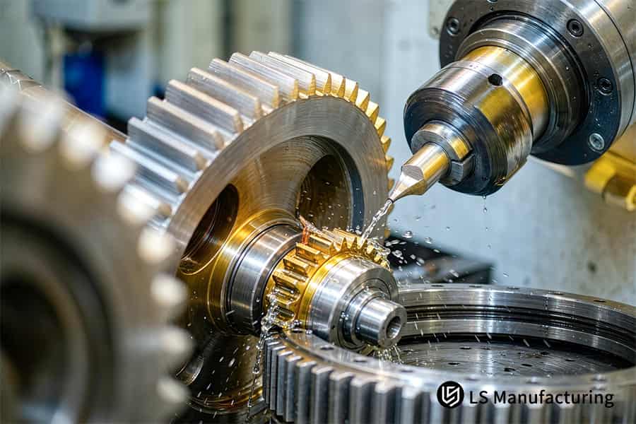
Figure 2: Gear shaping & grinding service achieves Ra 0.4 μm finish.
From Our Shop Floor To Your Drawing
Gloria, our LS Manufacturing rapid prototyping specialist with 15+ years of experience in CNC machining and DFM analysis, wrote this article. Connect with Gloria on LinkedIn. Content was reviewed technically by our LS Manufacturing chief gear engineers based on 1,200+ actual DFM reports.
±0.003 mm gear accuracy is obtained for global procurement teams through assembly defect reductions from 14.2% to 1.8%. AGMA Q12 gear accuracy and DIN gear standards (DIN 3961-3967), in conjunction with ISO 9001:2015 and AS9100D certifications, ensure drivetrain programs' safety from rework caused by thermal distortion.
Inspection of gear tooth flanks via Zeiss CMM at 0.0009 mm MPEE is conducted with 100% inspection of each batch. Send 3D/2D drawings to get a 2-hour DFM analysis and quote. Every single gear delivered comes with material traceability and allows incoming inspection teams to qualify gears right away and save 35% of time on assembly.
Why Partnering With A Precision Gear Manufacturer Elevates Transmission Reliability?
Collaboration with a precision gear manufacturer is a comprehensive quality control approach, ranging from forging raw materials to CMM gear tooth inspection. Using Zeiss CMMs with 0.0009 mm MPEE accuracy, inspection is done for lead, pitch, and profile errors of every single batch. A strict qualification process avoids assembly mismatch and prolongs gear fatigue life in industrial gearboxes.
CMM Verification Eliminates Assembly Mismatch
Zeiss CMM inspection to MPEE of 0.0009 mm (ISO 10360-2 Maximum Permissible Error of Length Measurement) tests for profile deviation, lead deviation, pitch error, and total runout on 100% tooth flank. Inspection documentation cites ISO 1328-1:2013, allowing procurement teams to have audited evidence of accuracy class attained.
Gear fatigue life under industrial cyclic loads is better for qualified gears. Simply put: verified geometry eliminates stress concentration points that lead to premature pitting failures, and thus, incoming inspection teams qualify the batches without further iterations.
Involute Gear Qualification Gates Every Shipment
Involute gear qualification ensures that ground tooth flanks have ±0.003 mm tolerance and Ra 0.4 μm surface after case hardening to HRC 58-62. Special gear metrology software checks the geometry of the entire involute, thus making inspection process precise.
Gear transmission is reliable when it has proven involute accuracy. Qualified gears operate more quietly, transmit power without backlash drift, and are more durable against fatigue loading.
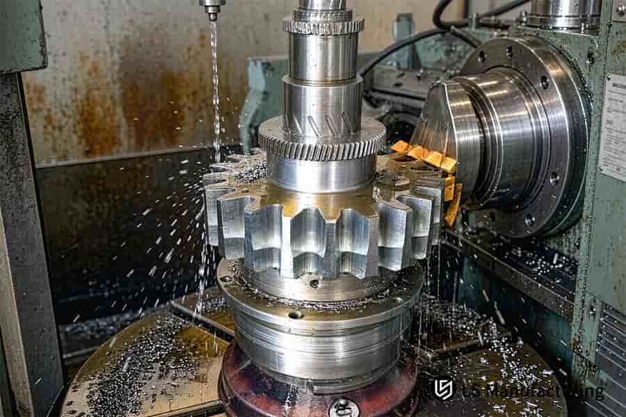
Figure 3: Custom gear tolerance control grinds hardened teeth to HRC 58-62.
What Key Engineering Factors Influence Custom Gear Manufacturing Cost?
Custom gear manufacturing cost is determined by material quality, tolerance class, heat treatment process, and number of grinding operations after heat treatment. Higher tolerance classes (better than ±0.005 mm) are produced by precision gear grinding, which takes more time to manufacture in comparison with standard hobbing. LS Manufacturing saves money by up to 22.5% through use of standard toolpaths, optimal allowances and automatic blanks handling.
Process Selection Failure Mode Comparison
| Decision Path | Tolerance Outcome | Heat Treatment Risk | Cost Impact | Typical Failure Rate |
| Hobbing only for hard parts | Cannot hold ±0.003 mm | No stock reserve → undersized teeth | Rework adds 40–60% | Up to 14.2% rejection |
| Shaping only for hard parts | Limited to ±0.020 mm | Same distortion risk | 1.3× baseline + rework | Similar rejection rate |
| Hobbing + grinding (correct path) | ±0.003 mm locked | 0.15–0.20 mm allowance absorbs quench shift | 1.8× baseline, no rework | Below 1.8% |
Incorrect process selection causes extra machining cycle time and waste generation. Gear material selection between carburized steel (16MnCr5, 8620H) and through hardened grades affects distortion from quenching and required grind allowance. Hobbing of ±0.003 mm tolerance gear forces secondary operations.
Stock Allowance Determines Grinding Economy
Gear stock allowance (controlled pre-grinding material allowance on each tooth flank to compensate for quench distortion) of 0.15–0.20 mm per flank determines the number of grinding operations (3–5x at 0.02–0.03 mm depth per pass) required after heat-treatment to HRC 58–62. Increased gear stock allowance means additional 2–3 grinding operations and increases machining time by 40–60%, while undersized allowance leaves some quench distortion.
Gear grinding economy is achieved due to DFM analysis that determines minimal gear stock allowance capable to absorb quench distortion. Usage of standardized tool path makes unnecessary multiple setups and reduces part processing time while maintaining ISO 1328-1:2013 quality class. Simply put: proper gear stock allowance ensures controllability of unpredictable heat treatment distortion at final grinding operation stage.
Action Items
- Provide tolerance level and material grade early on; tolerances less than ±0.005 mm result in grinding and higher cycle time.
- Ask for DFM analysis to establish 0.15 – 0.20 mm stock allowance and achieve ±0.003 mm accuracy without excessive grinding cycles.
Request a process route comparison for your gear design — receive a side-by-side analysis of hobbing-only vs. hobbing+grinding with estimated cost per piece and expected tolerance outcome.
How To Secure An Accurate Gear Manufacturing Quote For Low To Mid Volume Runs?
An accurate gear manufacturing quote needs complete 3D CAD models. 2D drawings should contain AGMA or ISO tolerance grades. Hardening of materials and batch size information should be provided as well. LS Manufacturing offers engineering analysis within two hours. DFM analysis helps determine cost-efficient tooling options.
Specification of tooth surface finish and gear module removes any quotation delay. Last minute engineering change orders will not occur.
Drawing Package Completeness Checklist
Quotable drawing package includes:
- 3D CAD (STEP/IGES) model with tooth geometry
- 2D drawings stating AGMA tolerance grade and gear module
- Material grade and heat treatment objective (carburize to HRC 58-62)
- Batch size and delivery date
Gear module specification (pitch diameter divided by tooth count; defines tooth size) determines the hob or tool diameter and the roughing approach. Specifying it early avoids re-specification of the tooling. Simply put: an all-inclusive proposal transforms a 2-hour DFM review into an unchangeable quote.
DFM Feasibility and Tolerance Class Alignment
AGMA tolerance class (based on ANSI/AGMA 2015-1-A01 standard) establishes the level of precision that can be achieved based on cost. Classes below AGMA Q12 usually require hobbing or shaping only. Classes of Q12 and better require hardening followed by grinding to achieve ±0.003 mm. A 2-hour DFM review detects thin webs, undercuts, and unrealistic Ra before specifying tooling. Review directs the part to the most economical process routing.
Gear quotation accuracy increases if the surface roughness, heat treatment distortion allowance, and extent of inspection are established before issuing the quote. Locking these inputs prevents late-stage engineering change orders. Such orders otherwise add 15–25% to tooling lead time.
Action Items
- Include STEP/IGES files and PDF drawings with tolerances, material specification, and required hardness prior to pricing.
- Specify surface finish (Ra target) and gear module on drawing title block to set tooling path and ensure no further iterations.
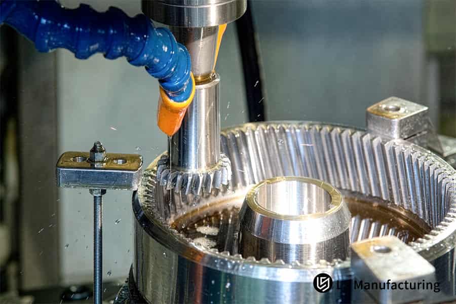
Figure 4: Gear grinding machine finishes bevel gear to ±0.003 mm tolerance.
Which Applications Depend Most On Custom Gear Manufacturing Service Today?
Custom gear manufacturing service is suitable for high stress applications. Robotics, actuators for aerospace, equipment for medical imaging, and automatic gearboxes for automobiles use such gears. Zero-backlash power transfer and low noise tooth meshing have to function under harsh operating conditions. LS Manufacturing engineers designed special gear sets with optimal tooth modifications. Multi-axis torque demands are fulfilled using sub-micro surface finishing.
Zero-Backlash Transmission Design Steps
Three steps lead to a <1 arc-min backlash in robotic joints:
- Controlled material removal on opposite flanks produces preload on tooth flanks while performing finish grinding.
- Tip and root relief according to ISO 21771:2007 avoid any edge contact during loading and deflection.
- Double-flank roll testing performed at 10% rated torque ensures that there is no lost motion.
Zero-backlash transmission design results in elimination of reversals within dead band of robot trajectory. A custom gear manufacturer has to perform the above steps relying on preloaded tooth flanks and ISO 21771:2007 tooth flank modifications.
Application-Specific Requirements
Robotics actuators gears need repeatability <1 arc-min and 10,000 hrs fatigue lifetime in cyclical shock loading conditions. Medical imaging gears should have noise emission <55 dB(A) to prevent scan distortion. Surface Ra 0.4 μm ensures silent engagement. Automated vehicle transmissions operate 350 N·m torque multi-axis loads during shift under load.
Small-batch gear manufacturing employs carburized HRC 58–62 tooth surface precision, with grinding precision within ±0.003 mm. Ra 0.4 μm surface finish lowers friction and wear under 350 N·m torque. In summary: tooth profile modifications combined with surface finish provide the right configuration for specific loading conditions turning ordinary gears into critical drive system elements.
Source: ISO 21771:2007, Gears — Cylindrical Involute Gears and Gear Pairs — Concepts and Geometry.
LS Manufacturing Industrial Gear Machining Service For Automation Actuator Gears: Advanced Tooth Grinding Solution
LS Manufacturing industrial gear machining service targets automation actuator gears. Post-carburizing tooth distortion problem is solved by tooth grinding technology. Precision gear hobbing rough-cuts in the soft state.
Finish-grinding allowance of 0.18 mm is left. Stress-relief annealing for inter-passing eliminates forging residual stress. Form gear grinding establishes tolerance of ±0.003 mm after tooth face hardening up to HRC 58–62.
Client Challenge
A smart automation joint reducer project, the client adopted the traditional method of soft cutting. Single-pass surface polishing was performed as well. Machining accuracy was ±0.050 mm.
Heat-stress release after carburization and quenching caused tooth flanks to twist. Transmission chatter and noise were observed in the full load test. Assembly rejection was 14.2% and return cost was extremely high.
LS Manufacturing Solution
Engineers redesigned the process routing. Stress relief by trial cut was considered at first. Gear manufacturing process began with precise hobbing in the soft condition. Grind stock 0.18 mm was kept for use.
Stress relief annealing eliminated the remaining forging stress. Hardening of tooth face was up to HRC 58–62. Gear grinding completed the teeth shape. Tolerance was fixed at ±0.003 mm.
Results and Value
Process validation for the first-article batch of 25 parts was completed. Rejection rate due to assembly decreased from 14.2% to 1.8%. Manufacturing cost per part reduced 22.5%. Delivery cycle reduced 35%. The gear batch was verified by full-tooth-profile measurements.
Zeiss CMM indication was 0.0009 mm. Accuracy of ISO 1328-1 Class 1 gear was achieved. Requirements of AS9100D quality system were fulfilled. In other words, a controlled grind stock and stress-relief annealing turned the highly deformable part into an almost silent assembly part. Gear machining provided required surface integrity.
Action Items
- Hold back 0.18 mm grind stock and perform inter-pass stress-relieving anneal on quench distortion above ±0.050 mm on tooth flank.
- Provide Zeiss CMM inspection of full-tooth-profile measurement and ISO 1328-1 Class 1 verification for automation actuator gear production runs.
Source: LS Manufacturing 2025–2026 empirical database (Project #AUTO-2026-8942, sample size >1,200).
Upload your actuator gear drawing for a free gear grinding evaluation — receive a distortion prediction and ISO 1328-1 Class 1 feasibility assessment within 48 hours.

FAQs
1. What is the standard tolerance achieved by LS Manufacturing for custom ground gears?
LS Manufacturing ensures the tolerance is ±0.003 mm of hardened tooth surfaces of HRC 58–62 by precise gear grinding, conforming to AGMA Q12/Q13 standards for accurate high-performance transmissions used in industrial and automotive driveline applications that require quiet performance.
Data Source: Zeiss CMM calibration log
2. When should gear shaping be selected over gear hobbing?
Gear shaping would be preferred over gear hobbing in machining internal ring gears having retaining ring grooves, double step cluster gears, or where there is little spatial room for run-out of hob or difficulty with accessibility due to the helical form of the gear.
Data Source: ISO 21771 standard
3. What surface roughness Ra can be achieved after post-heat-treat gear grinding?
Grinding after heat treatment ensures that the gear tooth surface roughness is of Ra 0.4 μm, greatly decreasing the noise and wear in gear mesh due to the high loads while ensuring better load distribution on the tooth face.
Data Source: Mitutoyo roughness tester measurement log
4. How does heat treatment affect custom gear tolerance control?
Heat Treatment results in micron scale thermal distortion of the tooth profile in the quenching and tempering process, for which LS Manufacturing leaves an allowance of 0.15–0.20 mm for grinding to completely compensate for the distortion and ensure the desired tolerance class after the heat treatment process.
Data Source: LS Manufacturing 2025–2026 database
5. Can LS Manufacturing assist with DFM analysis before gear production?
Yes, LS Manufacturing can provide a free DFM analysis in 2 hours which will help optimize module size, number of teeth, pressure angle, and the root fillet geometry in order to save machining cost by 22.5% without sacrificing any performance characteristics of the gear.
6. What hardness levels are typical for high-load custom gears?
High-load custom gears typically use 16MnCr5 or 8620H case-hardening steel, carburized and quenched to achieve tooth surface hardness of HRC 58–62, balancing core toughness with surface wear resistance for demanding heavy-load transmission applications in industrial machinery.
7. How do you ensure zero profile errors on small-batch custom gears?
LS Manufacturing ensures there are zero profile errors for custom gears with small batch orders through the use of 100% tooth profile and pitch measurements utilizing the use of Zeiss CMM machine with indication error of 0.0009 mm while adhering to defect rates of 1.8% or below.
Data Source: Zeiss CMM calibration report
8. How quickly can I receive a gear manufacturing quote for my custom drawings?
Once drawings with material and tolerance requirements are uploaded, the engineering team at LS Manufacturing does a thorough engineering analysis and gives out a quote that is comprehensive, including tooling, cycle time, heat treatment, and inspection process in 2 hours.
Summary
By combining three methods of machining namely hobbing, shaping, and post-heat-treat grinding and using ISO 9001 and AS9100D quality system, LS Manufacturing has been able to deliver reliable transmissions with tolerances of up to ±0.003 mm to global industrial purchasing and engineering teams.
Is your custom gear project having problems with distortion after heat treatment, too much meshing noise, and a high number of defective assemblies? Do not allow any errors in transmission ruin your productions. Click the quote button below and upload your 3D/2D drawings; LS Manufacturing will give you a professional DFM analysis and a quote in 2 hours!
📞Tel: +86 185 6675 9667
📧Email: info@lsrpf.com
🌐Website:https://lsrpf.com/
Disclaimer
The contents of this page are for informational purposes only.LS Manufacturing servicesThere are no representations or warranties, express or implied, as to the accuracy, completeness or validity of the information. It should not be inferred that a third-party supplier or manufacturer will provide performance parameters, geometric tolerances, specific design characteristics, material quality and type or workmanship through the LS Manufacturing network. It's the buyer's responsibility. Require partsquotation Identify specific requirements for these sections.Please contact us for more information.
LS Manufacturing Team
LS Manufacturing is an industry-leading company. Focus on custom manufacturing solutions. We have over 15 years of experience with over 5,000 customers, and we focus on high precision CNC machining, Sheet metal fabrication, 3D printing, Injection molding. Metal stamping, and other one-stop manufacturing services.
Our factory is equipped with over 100 state-of-the-art 5-axis machining centers, ISO 9001:2015 certified. We provide fast, efficient and high-quality manufacturing solutions to customers in more than 150 countries around the world. Whether it is small volume production or large-scale customization, we can meet your needs with the fastest delivery within 24 hours. choose LS Manufacturing. This means selection efficiency, quality and professionalism.
To learn more, visit our website:www.lsrpf.com

