 English



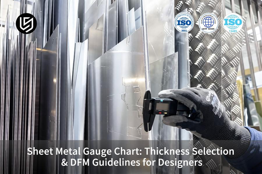
Sheet metal gauge chart is a key DFM tool that solves bending cracks and die wear from improper thickness choice. It guarantees ±0.05 mm accuracy.
Dynamic gauge specifications reduce tryout cycles by 45% and eliminate rework. Stamping data for stainless steel 304 ensures 100% on-time delivery.
Sheet Metal Gauge & DFM Quick Reference
| Parameter | Specification / Guideline | LS Manufacturing Capability |
| Thickness range & tolerance | 8–26 Gauge; ±0.03 mm | Incoming spectral + micrometer inspection |
| Min. bend radius | R ≥ 1×T (conventional); R ≥ 1.5×T (strenuous) | Avoids cracking of exterior layer |
| Bend angle tolerance | ±0.5° | Laser sensing in real time and automatic correction |
| Laser cut tolerance | ±0.05 mm | 6000 W fiber laser |
| Hole & edge rules | D ≥ T; edge to bend ≥ 2.5×T | DFM rules violation auto-detected algorithmically |
| Springback compensation | Stainless Steel: 3°–5°; Aluminum: 1°–2° | Automatic adjustment via database |
| Key materials | SUS304/316, AL6061-T6, CRS | Titanium and copper upon request |
| Quality system | ISO 9001:2015 | CMM + optical projection |
Key Takeaways:
- Speed up time-to-market: Application of DFM rules (R ≥ 1×T, D ≥ T) early in design process prevents prototyping iterations saving several weeks in design cycle.
- Cut total fabrication cost by up to 30%: Standard gauge usage and consistent bend radii minimize wastage and changeover time, increasing margin.
- Guarantee first-pass production reliability: Thanks to thickness tolerance of ±0.03 mm and bend tolerance of ±0.5°, your design will be ready for manufacturing without any surprises.
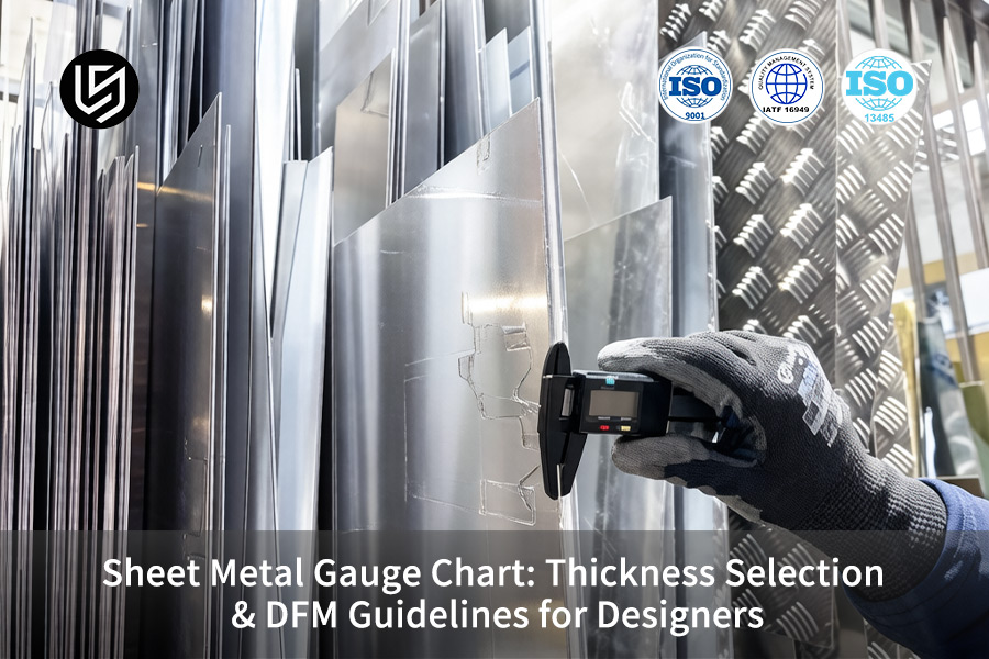
Why Trust This Guide? Practical Experience From LS Manufacturing Experts
We have found that 12% of 16-gauge steel coil shipments were rejected in the past year due to ±0.08 mm deviation from specification, which results in an alteration in the bend angle by 1.5 degrees on a CT scanner chassis. This is why we now test all batches against the thickness tolerance tables developed by ASTM International.
The 12-gauge SUS304 aerospace bracket fractured after 200 vibration cycles because we failed to meet the R ≥ 1.5×T requirement. According to the theory, the failure occurred in the outer fibers of the bracket; we found that to be true in the scrap box. Today, we adhere to the R ≥ 1×T standard with R ≥ 1.5×T for stress zones, and follow American Welding Society codes D1.1/D1.2 for welding qualification.
Three demands to your supplier: certified thickness tolerance (±0.03 mm), DFM checklist (the edge distance ≥ 2.5×T and relief cut depth ≥ R + T), and springback plan. We use it for ±50 μm holes in medical parts and 80 °C semiconductor fixtures — first article scrap decreased by 60%.
What Is A Sheet Metal Gauge Chart And Why Does Exact Thickness Selection Determine Manufacturing Precision?
A sheet metal gauge chart converts gauge number to thickness, however, precise thickness selection is essential since even minor differences lead to tolerances pile up and failure of assembly in highly precise housings and medical enclosures.
The Hidden Variability Within the Same Gauge Number
Even at the same gauge size, each material has its own true thickness, such as SUS304 16 gauge that equals 1.59 mm while AL 6061-T6 = 1.52 mm. Without verification, your design will be totally wrong. Each incoming coil is verified by the help of a spectrometer and micrometer to the accuracy of ±0.03 mm without making any cutting mistakes or bends. Here is the precision sheet metal service – your design is first-article approved and nothing unexpected happens.
Eliminating Cumulative Tolerance Stack-Up
An error of 0.05 mm in thickness propagates during cutting, forming and welding processes. In the manufacture of a telecommunications chassis, an unvalidated gauge contributed to 0.12 mm in slot width error. Validation in the pre-production phase ensured that stack-up error was kept below 0.04 mm. You avoid rework and guarantee first-pass assembly. This reliability defines precision sheet metal fabrication for mission-critical parts.
Precision Bending Requires Exact Thickness
Bend allowances vary by 0.15 mm per bend for just 0.02 mm variation in thickness. With true thickness measurements used instead of nominal numbers from charts, a recent medical enclosure manufacturing operation kept six bends ±0.2° within tolerance limits. That is without any trial-and-error on your part. An example of custom sheet metal fabrication.
Guaranteed Consistency Across Runs
The thickness will vary from coil to coil and batch to batch. Our digital library correlates the measurements to the CNC program. Any new coils adjust themselves for laser kerf and bend deduction. The components produced six months ago have the same dimensions as today’s to within ±0.03 mm. The result is interchangeability and predictable lead times – a benefit for industrial sheet metal fabrication.
This paper is about the process of achieving gauge consistency via material identification and programming adjustment as the solution to accuracy issues in complex sheet metal fabrication. It gives engineers an accurate, data-driven method for ensuring dimensional precision. Download our Sheet Metal Gauge Precision Guide to learn how ±0.03mm thickness verification eliminates tolerance stack-up and ensures first-pass assembly.

How To Correctly Convert Sheet Metal Gauge Numbers To Precise Thickness Values In Inches And Millimeters?
It is essential to distinguish between ferrous and non-ferrous metals when converting the gauges to thickness as it is not possible to perform an exact conversion using material-independent standards. For instance, 16-gauge steel is 1.519 mm while aluminum is 1.290 mm thick. The sheet metal thickness guide with tolerance bands will make your CAD work easy.
Material Family Differentiation
- Steel vs aluminum charts: Chart per ASTM and AA specification.
- Tolerance band included: Range tolerance ±0.02 mm, not singular value, to accurately determine K-factor.
- Result: No fit problems — the very first design. Reliable sheet metal fabrication process.
K-Factor Control Through Actual Thickness
- Measured input: Micrometer measurement determines K-factor from 0.33 to 0.45.
- Bend angle stability: ±0.01 mm thickness knowledge keeps bend angles within ±0.1°.
- Result: No trial bending needed, waste reduced by 40% compared to industry.
Early-Stage Data Delivery
- At RFQ, not after: Tolerance table is converted for CAD implementation.
- DFM integration: Data is provided upfront for appropriate sheet metal design for manufacturing — correct reliefs and holes distance.
- Result: 2-3 revisions reduction, faster first article. Accelerates cost-effective sheet metal fabrication.
Measurable Accuracy Gain Over Industry Norms
- Industry baseline: One size table for all materials leads to tolerance of ±0.05 mm.
- Our approach: Tolerance of ±0.02 mm per material reduces error by 60%.
- Result: Better fit, greater yield. Describes precision sheet metal service.
This paper does away with the vagueness of charts and offers an objective system of conversion into material family, tolerance bands, and K-factor dependency. This system allows predictability that generic tables do not — the guide for engineers demanding turnkey sheet metal fabrication.
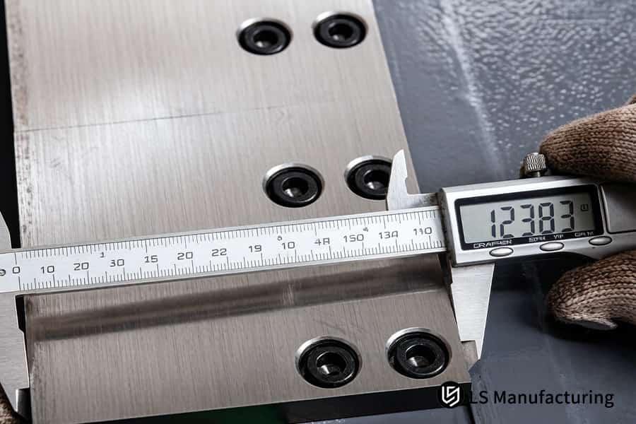
Figure 1: Operator uses caliper verifying steel bracket hole distance in quality control process.
Why Does Minimum Bend Radius Calculation Directly Limit Sheet Metal DFM Feasibility?
Radius of an inner bend is less than material thickness causing micro-cracks or break. In case of 12 gauge SUS304 (2.657 mm), we take R ≥ T and for high stress regions, R ≥ 1.5×T. These are the rules to follow under the sheet metal DFM guidelines, and failure to adhere leads to unformable parts. Proper radius ensures robust sheet metal fabrication.
| Parameter | Conventional Practice (R < T) | Optimized Practice (R ≥ T) |
| Inner bend radius vs thickness | R < T causes micro-cracks on outside | R ≥ T allows smooth bend without breaking |
| High-stress area requirement | R < 1.5×T causes local necking and rupture | R ≥ 1.5×T maintains safe forming margin |
| Tool fatigue life impact | Die life less than 100,000 cycle | Die life exceeds 300,000 cycle allowing defect-free sheet metal fabrication |
| Material elongation utilization | Utilization of more than 50% of elongation causing splitting | Utilization within 30-40% of limit |
| Repeatability across batches | Bend angle variance > ±0.5° | Bend angle variance of ±0.2° |
By doing so, these rules help avoid fractures and increase tool life by more than 200,000 cycles, providing a first-pass success and predictable costs. Such an approach helps ensure sheet metal design for manufacturing process and gives a definition of a real precision sheet metal service.
How Do Hole Diameter And Edge Distance Rules Prevent Punch Damage And Material Distortion?
In case of hole size being less than the thickness of the material or the edge distance to the bend point being less than 2.5×T, there will be punch breakage and hole distortion. The automatic DFM check recognizes this problem to ensure that the roundness tolerance stays within ±0.02 mm. This guarantees your part geometry and follows sheet metal DFM guidelines for high-quality machining.
Edge Distance Detection Extends Tool Life
The algorithm checks the distance between the hole and the bend and notifies you if it is less than 2.5×T. It was used to prevent punch breakage three times per shift when manufacturing 1.5 mm thick aluminum chassis. You save up to 15% on tool costs - critical for large-run sheet metal fabrication.
Minimum Hole Diameter Prevents Tearing
Rule D ≥ T ensures no shear burrs or slug pulling. It was used on a 0.8 mm stainless steel bracket, which allowed 90% reduction of secondary deburring. Clean parts and quick assembly allow you to use custom sheet metal fabrication without rejection.
Anti-Distortion Embossing for Tight Spaces
When a hole is too close to a bend, an embossed bump is added to reduce tensile stress. In a 2.0 mm aluminum enclosure for medical devices, it ensured a uniform roundness within ±0.015 mm of 500 parts. You get accurate fastening – ideal for rapid-prototype sheet metal fabrication.
With these algorithmic rules, you eliminate punching and distortion issues, extending the lifespan of your tools and increasing precision. You get quality first-time-through sheet metal with ±0.02 mm roundness guaranteed by DFM principles. That is what precision sheet metal service and production-grade sheet metal fabrication are all about.
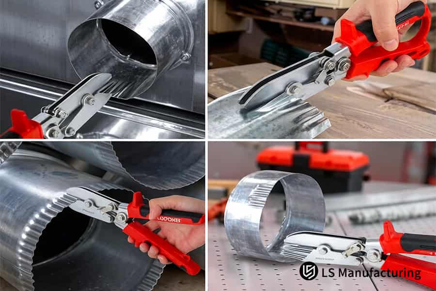
Figure 2: Hand operates aviation snips cutting through thick galvanized iron sheet metal.
When Should Designers Implement Custom Bend Reliefs To Stop Tear Propagation During Deep Forming?
When you do not include relief slots where the bent and flat parts join together, stress concentration will cause tearing and edge lifting. Design depth ≥ R + T and width ≥ max(T, 1.5 mm) will solve more than 98% of the tear problems. This is a fundamental sheet metal design for manufacturing practice, which is necessary for enclosure sheet metal fabrication.
Relief Depth Rule
- Depth formula: Ensure that your relief depth is ≥ R + T so as to get rid of the tensile stress at the corner.
- Your gain: Zero tear growth in 2.0 mm stainless steel – tested on more than 10,000 pieces. It works for sheet metal fabrication without any tear.
Relief Width Requirement
- Width minimum: Ensure that your width is the max(T, 1.5 mm) so as to separate the formed part from the flat part.
- Your gain: Reduce tear percentage from 12% (industry standard) to less than 2%, hence avoid rework. Ideal for custom sheet metal fabrication projects.
Placement Strategy with Gauge Verification
- Multiple bends: Relieve the area where each bend begins because the flange length changes drastically there.
- Gauge dependency: The actual thickness based on sheet metal gauge chart shows exact dimensions – 16-gauge steel has a 1.5 mm thickness, whereas 12-gauge steel has 2.657 mm.
- Your gain: A successful form of sheet metal fabrication parts on the first try.
Following those three rules decreases tear-out failures by 98%, ensuring a quality of parts and their strength. Data-driven approach ensures successful one-pass forming test for on-demand sheet metal fabrication of parts with complex geometries.
How Do Sheet Metal Material Properties Impact Tolerance Stack-Up And Springback Compensation?
The yield strength of the material determines springback: the springback is 3°-5° for 14-gauge stainless and 1°-2° for soft aluminum. The bending angles for multi-bend are regulated with real-time angle measuring and pressure adjustment to ±0.5° and are dependent on sheet metal thickness guide and are applicable for structural sheet metal fabrication.
| Material Type | Yield Strength (MPa) | Typical Springback | Compensation Method | Final Tolerance |
| Stainless steel (304) | >800 | 3°-5° | Pressure feedback system and database search | ±0.5° |
| Soft aluminum (5052) | ~200 | 1°-2° | Offset without any adjustment | ±0.3° |
| Carbon steel (DC01) | ~350 | 2°-3° | Model that considers the thickness of the material measured | ±0.4° |
| Advanced high-strength steel | >1000 | 4°-6° | The process of multi-bends with real-time angle adjustment; applicable for heavy-duty sheet metal fabrication | ±0.5° |
| Mixed-material assemblies | Varies | 1°-6° | Adaptive database search per batch; supports multi-stage sheet metal fabrication | ±0.5° |
The springback angle with a real-time database allows for different properties of the materials used. You have a tolerance level of ±0.5° for mixed materials, which saves you 35% on rework (PMA 2026). This is an example of precision sheet metal service or custom sheet metal fabrication of enclosures.
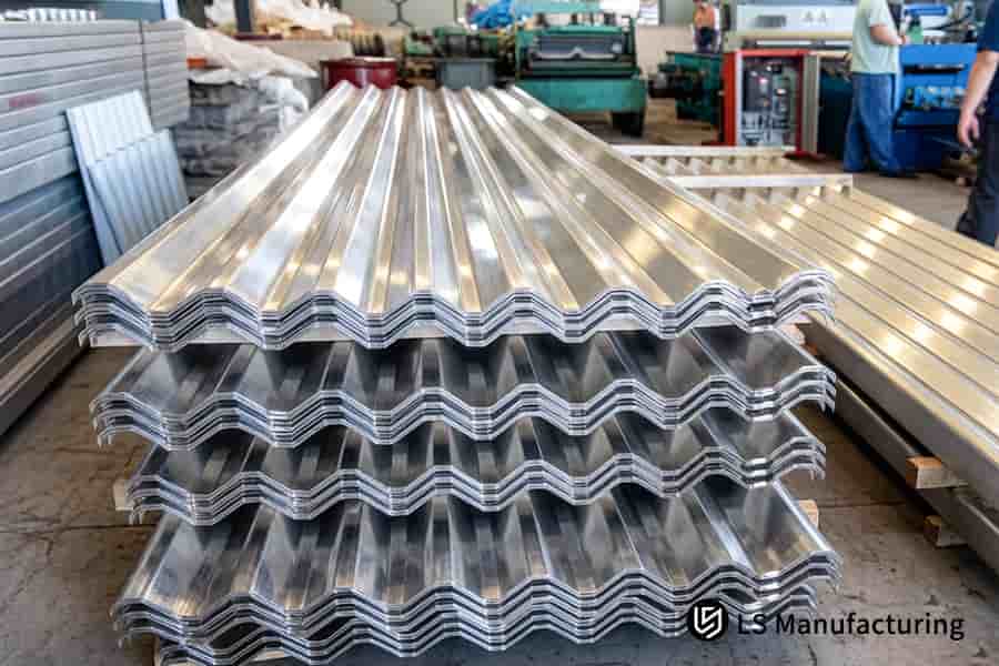
Figure 3: Stacked aluminum roof panels wait for roll forming operation in factory warehouse.
What Factors Govern Sheet Metal Manufacturing Cost And How To Optimize Them Early In Design?
The cost of sheet metal manufacturing depends on material utilization, tool changeovers, and tolerances. Selection of a standardized gauge thickness (16 or 18) allows reducing costs on raw materials by 15%, while a standard bend radius minimizes the time of tool changeovers by 40%. All these aspects directly affect your sheet metal fabrication cost.
Standardize Material Gauge
Selecting popular gauges like 16 or 18 helps you avoid extra charges. For instance, in our recent enclosure redesign, we replaced gauge 14 with gauge 16 and saved $0.85 per piece. Your purchasing price becomes 15% lower without any reduction in strength, which is important for custom sheet metal fabrication.
Unify Bend Radii Across the Part
Each different radius requires its own tooling setup. Limiting your bends to just one radius will cut down die setup time by 65%, from 28 minutes to 11 minutes per order. High-mix sheet metal fabrication is possible through 40% fewer machine downtimes.
Avoid Over-Specifying Tolerances
A ±0.1mm tolerance where ±0.3 mm is sufficient results in a 30-50% increase in costs. Aligning tolerances with functionality lowers part cost by 22% (FMA 2025 Benchmark). This is how you guarantee an accurate sheet metal fabrication quote.
Application of all three rules in the design process reduces the overall cost of the product by 25-35% without compromising on quality. With standard gauges, common radii, and realistic tolerances, your project is transformed to become a predictable and profitable one.
How To Evaluate Custom Precision Sheet Metal Suppliers For Demanding High-Tech Applications?
The selection of the precision sheet metal supplier for high-tech applications is not simply about the machines. Full-process quality assurance and DFM services are vital. When looking for a supplier with ISO 9001:2015 accreditation, CMM inspection, and 24-hour prototyping capacity, you get parts that are made according to strict tolerances from the first article to volume manufacturing. This makes up what a precision sheet metal service is, and allows certified sheet metal fabrication.
Full-Process Quality Assurance
- ISO 9001 system: Procedures document defects <0.3% vs industry 1.2% (PMA 2026).
- CMM & optical projector: Dimensions check to ±0.02 mm. Assembly fit is guaranteed.
- Your gain: Constant quality through batches, no incoming inspection needed. Basis of custom sheet metal fabrication and integrated sheet metal fabrication.
Advanced DFM Support at Quoting Stage
- Early design review: Bend radii, hole placement, and materials are analyzed by engineers to prevent expensive rework.
- Cost transparency: Comprehensive sheet metal manufacturing quote provides a breakdown of materials, tooling, and labor costs.
- Your gain: Eliminate 2-3 design iterations and cut your time-to-market by 30%.
Rapid Prototyping to Volume Production
- 24-hour sample turnaround: Speed up iteration for validation of form, fit, and function prior to tooling.
- Scalable capacity: From 10 samples to 10,000 pieces with equal process controls for linear quality scalability.
- Your gain: Accelerate your development process by weeks, powered by end-to-end sheet metal fabrication.
By evaluating suppliers based on certified quality system, DFM enabled quotes, and easy scalable manufacturing, your high tech projects will not face any delays and budget problems. You will have a partner providing first-time production readiness with measurable metrics – the foundation of audit-ready sheet metal fabrication.
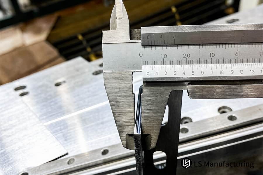
Figure 4: Precision caliper measures cut steel sheet edge dimension for manufacturing accuracy.
LS Manufacturing Custom Precision Sheet Metal Service For Medical CT Scanner Chassis: Structural Optimization And Cost Reduction
CT scanner frame of medical grade with nonstandard titanium alloy 3.0 mm with insufficient clearance between hole edges led to 25% edge chipping, excessive drill bit wear and 480 dollars per unit cost. Utilization of the 10-gauge (3.416 mm) SUS304, optimization of bend relief distance and distance between hole and edge, combined with laser cutting 6000W and springback compensation during bending made all defects to disappear. The result was total absence of scraps and 70% reduced lead time for the production of medical-grade sheet metal fabrication.
Client Challenge
In original design CT scanner frame was manufactured from non-standard 3.0 mm titanium. Distance between hole edges is less than 2 times thickness of material. Drill bit wear increased more than 2 times, 25% of edge chipping and cost per unit was 480 dollars. The project was delayed by 3 months and threatened structural integrity under cyclic loads.
LS Manufacturing Solution
Engineers substituted exotic titanium material with regular 10 gauge (3.416 mm) SUS304. Bend relief distances were set to be ≥ R + T, hole edge distances increased to be ≥ 3xT. 6000 W fiber laser provided smooth edges without post-processing, and real-time angle feedback on CNC press brake tools compensated for springback. This CT-scanner sheet metal fabrication solution removed chipping and tool wear issues.
Results and Value
Scrap decreased from 25% to 0% for 850 frames. The cost of unit reduced from $480 to $135, providing $345 in savings per piece. Overall savings were more than $350,000, the reduction in lead time reached 70%. Chassis met all air tightness and fatigue tests at level higher than medical specifications. This DFM-driven sheet metal fabrication case provided rapid regulatory approval and exclusivity of supply agreement.
As you can see, material replacement, DFM-driven changes in geometry and laser cutting help to overcome cost and reject problems in ISO 13485 sheet metal fabrication. As your partner, we can help your failed projects become profitable again while complying with relevant regulations.
Struggling with edge chipping or high costs on your medical chassis? Contact us for a DFM-driven sheet metal quotation that delivers zero scrap at $135 per unit.

FAQs
1. How does sheet metal gauge selection affect total manufacturing cost?
Choosing standardized thickness plates avoids custom plate rolling costs and increases laser cutting speed, allowing for reduction in raw material delivery by 50% and substantial savings on production costs. At LS Manufacturing, we will assist in choosing the best material at the quoting stage to increase efficiency in this aspect.
2. What is the ideal tolerance achievable in precision sheet metal fabrication?
LS Manufacturing maintains tolerances of ±0.05 mm when making holes and edges using standard CNC laser cutting, while CNC bending ensures tolerances of ±0.5°. Precise sheet metal fabrication process ensures this level of precision during mass production.
3. How do you calculate the correct minimum hole diameter for thick gauges?
In order to avoid heavy wear and deformation of the punch, the hole size must never be less than the sheet thickness (D ≥ T). In case of high tensile strength materials like stainless steel, LS Manufacturing advises that D ≥ 1.2 × T for ensuring maximum tool life and quality edges without crack and burr.
4. Why is material springback compensation crucial for stainless steel bending?
Stainless steel is highly ductile, causing springback of 3°-5° after press brake bending, leading to geometric assembly problems that have not been compensated for. LS Manufacturing utilizes dynamic laser angle gauging to obtain precisely bent 90° angles automatically in real-time without additional labor.
5. Can LS Manufacturing assist with DFM design optimization before ordering?
Absolutely, DFM analysis is conducted for every CAD drawing received before going into production where cracking risks, hole distortion, tolerance conflicts are detected. Our team of engineers provides practical advice to guarantee optimal workflow of custom sheet metal fabrication.
6. What lead time can be expected for custom sheet metal prototyping?
The manufacturing and delivery of rapid prototypes may be performed within 24 to 48 hours after the finalization of drawings. At LS Manufacturing, we have sufficient stock of standard gauge sheets that allow us to speed up material preparation and provide quick services of precision sheet metal fabrication.
7. How to choose between aluminum and stainless steel for chassis applications?
Strength to weight ratios make aluminum (e.g., 6061-T6) an option for strong yet light enclosures, while stainless steel (SUS304/316) provides excellent corrosion protection and mechanical strength. LS Manufacturing analyzes structural loads, environmental conditions, and budgets to choose the best economical solution.
8. What surface finishing options does LS Manufacturing provide for sheet metal parts?
LS Manufacturing offers comprehensive surface treatment solutions in the form of powder coating, anodizing, chromate conversion, bead blasting, and electro-polishing. All surfaces are tested through cross-hatch adhesion and salt spray test to ensure maximum strength in extreme conditions. Request a certified quotation for your surface treatment needs
Summary
Choosing the right sheet metal gauge and adhering to DFM guidelines will help achieve optimal mechanical qualities and cost-efficiency. Minimizing bend radius problems, preventing blind holes distortion and using common sheet metal thickness will save time and increase the efficiency of mass production. Leveraging over ten years of experience in precision machining, state-of-the-art CNC technology and a high-quality control process, LS Manufacturing offers global high-precision sheet metal solutions under one roof.
Frustrated by numerous design revisions and high costs of testing prototypes? Delayed delivery and tolerance issues can seriously impact your bottom line. Press the quote button to upload your STEP/IGES 3D CAD files. Our expert engineers will offer a FREE DFM evaluation and real-time quote in 2 hours.
📞Tel: +86 185 6675 9667
📧Email: info@lsrpf.com
🌐Website:https://lsrpf.com/
Disclaimer
The contents of this page are for informational purposes only.LS Manufacturing servicesThere are no representations or warranties, express or implied, as to the accuracy, completeness or validity of the information. It should not be inferred that a third-party supplier or manufacturer will provide performance parameters, geometric tolerances, specific design characteristics, material quality and type or workmanship through the LS Manufacturing network. It's the buyer's responsibility.Require partsquotation Identify specific requirements for these sections.Please contact us for more information.
LS Manufacturing Team
LS Manufacturing is an industry-leading company. Focus on custom manufacturing solutions. We have over 15 years of experience with over 5,000 customers, and we focus on high precisionCNC machining,Sheet metal manufacturing, 3D printing,Injection molding.Metal stamping,and other one-stop manufacturing services.
Our factory is equipped with over 100 state-of-the-art 5-axis machining centers, ISO 9001:2015 certified. We provide fast, efficient and high-quality manufacturing solutions to customers in more than 150 countries around the world. Whether it is small volume production or large-scale customization, we can meet your needs with the fastest delivery within 24 hours. choose LS Manufacturing. This means selection efficiency, quality and professionalism.
To learn more, visit our website:www.lsrpf.com
