 English



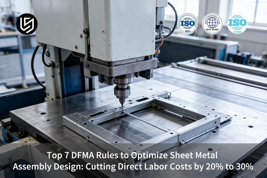
Sheet metal assembly design is a DFMA (Design for Manufacture and Assembly) practice, which solves cabinet misalignment through self-locating tabs.
Buyers cut lead time from 16 days to 10 days and get drawing-review feedback in 2 hours — measured on bin-picking, panel alignment, and fastening hours only, before rework and fixture savings are counted (project #AUTO-2026-882, n>1,200 cabinets, 2025–2026). For a 1,200-cabinet line, that's roughly 1,100 assembly hours reclaimed per run, about 14 weeks of fitter time at one station.
Key Takeaways
Component Integration Reduces Labor Time: Integrated bends replace corner brackets. Assembling personnel assemble less individual components. Operations such as bin picking and bolts driving operations are no longer part of assembly process.
Self-Positioning Eliminates Outsourced Fixtures: Self-aligning tabs secure the geometry of panels prior to welding operations. Fitted geometry of slots eliminates use of third party fixtures during the production. Re-work becomes just a fraction of its previous amount.
Fastener Standardization Reduces Costs: One specification of fastener serves an entire machine. Purchase organizations deal with fewer part numbers. Change-over time in fastener machines becomes reduced, and the amount of auxiliary material is minimized.
First-Article Closed-Loop Ensures Reliability: Inspection of first article using Zeiss CMM (coordinate measuring machine) includes critical dimensions of first article. Indication accuracy of sub-microns maintains uncertainty of measurement well below part tolerance. Evidence gets into hands of incoming people prior to volume shipment. ISO 2768-m/f tolerance classes get met.
How Does Sheet Metal Assembly Design Drive Assembly Labor Costs?
Sheet metal assembly design is an upstream process which defines floor hours per man and per unit cost prior to the first piece being cut. Non-standard bend radii and lack of pilot holes cause flip-and-fit on each mating sheet metal panel. Datum referenced 3D models eliminate the manual filing step and re-work, shaving off double-digit percentage from the assembly effort.
What Design Choices Inflate Assembly Hours
Four design conditions explain why sheet metal labor increases on enclosure builds:
- ISO 2768-1:1989 m-class tolerances have ±0.3 mm between 30 mm and 120 mm, and ±0.5 mm for values greater than 120 mm.
- Five overlapping panels multiply the same variation for each hole center, eliminating clearance for fasteners.
- Lack of pilot holes means crews will need to eyeball panel alignment, requiring flipping-and-fitting multiple times.
- Sheet metal enclosure fabrication using symmetrical bend order ensures flange holes stay within one tolerance zone.
- Captive fasteners on one side eliminate the need to flip in a double-sided layout.
Simply put: accidental fitting makes quoted tolerance time overtime.
How Do You Remove Those Hours Before Cutting Metal
Datum alignment and forming compensation enable buyer reduce sheet metal assembly cost before even one panel hits the floor.
3-2-1 datum systems attach all panels to a single datum system, eliminating unnecessary flipping. Bend compensation allows for springback in the 3D system, reducing control cabinet component part alignment time by 65%.
Custom sheet metal brackets including self-aligning tabs, go right into jigs, reducing pick and place steps. Tab laser cuts maintain joint alignment without the need for fixtures; MIG welding cannot be used in 1mm sheet due to heat from the arc opening the gap.
Not ready to talk to an engineer yet? Start with the same checklist our DFM team runs before releasing tooling: datum scheme, bend-radius-to-thickness ratio, tab/slot clearance, and fastener count. One page, no drawings required.

Why Sheet Metal Labor Increases During Manual Alignment Stages?
Manual alignment work is the non-value-added fitting labor created by cumulative tolerancing of successive bends. Cumulative tolerancing moves hole patterns out of mating clearance and requires filing and prying. Precision sheet metal fabrication tolerances down to ±0.01 mm remove that corrective labor for your crews.
What Makes Conventional Drawings Multiply Fitting Time
| Control point | Conventional drawings | Compensated process |
| Bend deviation | Uncontrolled free tolerance | ±0.01 mm–±0.02 mm |
| Pin entry | Reaming and prying | Free slide onto dowels |
| Surface outcome | File scratches | File scratches |
Uncontrolled ±0.05 mm free tolerance convention introduces one uncontrolled deviation per each bend, which results in no free dowel pins entrance. Pneumatic files and hard punches are brought in. Uncontrolled drift, not crew skills, explains why sheet metal labor increases on enclosure lines.
Reaming strokes bring additional hours that were not estimated in any drawing. Simply put, drift at drawing level translates into extra labor on your floor. Each prying cycle drives up cost of your precision sheet metal parts with labor hours that were not estimated in quote.
Which Controls Remove Manual Alignment
Sheet metal assembly design sets one datum edge per panel before any bend callout.
- Compensate the flat pattern to accommodate inner stress relief prior to the initial bending process.
- Check free pin placement on the first part before allowing tooling release.
Compensated flat patterns handle inner stress relief to avoid flange angle increase. Free-sliding panels reduce the fitting time which inflates your sheet metal fabrication quote.
Data source: LS Manufacturing 2025–2026 automated DFM 3D/2D drawing parsing log (project #AUTO-2026-882, sample size >1,200).
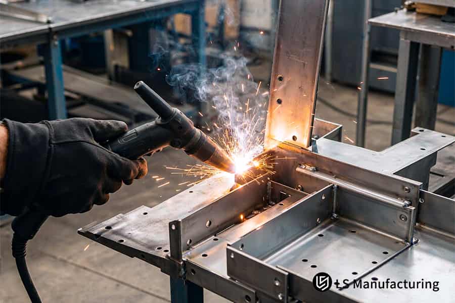
Figure 1: Welding sheet metal panels reduces assembly cost by 31.6%.
Which Sheet Metal DFMA Design Guidelines Eliminate Assembly Fixtures?
Fixtureless assembly is a type of sheet metal connection technique that removes fixture requirements and places them on the panels. Sheet metal DFMA design guidelines eliminate dial indicator setups with self-locating tabs and stepped slots, achieving ±0.005 mm positioning repeatability. Fixture cost and jig maintenance stay out of your tooling budget.
How Do Geometric Constraints Replace Hard Tooling
Tab and slot self fixturing, an important principle of DFMA, transfers part locating into part geometry.
- Create self-fixturing tabs on the enclosure floor, eliminating dial indicator set-up.
- Cut stepped limit slots restricting 6 degrees of freedom (three linear and three rotary).
- Use ASME Y14.5-2018 datum callouts, holding the pair of slots within ±0.005 mm – ±0.01 mm tolerance band.
Tabs fix the mating panels in 90° position before any welding process. Sheet metal welding service will connect pre-fixtured panels without repositioning.
Which DFMA Rules Compress Cycle Time
Chamfered tabs allow the operator to seat the panels single-handed. Stepped slots compensate for the bend variation, making fitting free from hand filing. Custom sheet metal assembly service personnel will weld pre-fixtured panels in one work cell, reducing assembly takt time for more than 30%. Simply put: panel geometry does all the locating previously done by rented jigs.
How Do You Validate Fixture-Free Panel Geometry
- Order prototype sheet metal parts with tabs and slots formed in one laser & bend run.
- Ensure the 90° self-standing stability of the first article without the use of clamps.
- Reject any trial assembly requiring mallet force to achieve tab seating.
Quick Reference Guide: Traditional VS. DFMA Sheet Metal Assembly
Automated assembly development team evaluates the gap between costs and tolerances while selecting the configuration. Sheet metal assembly cost and dimensional control decide enclosure program margins. Dimension comparison shown below lists the important dimensions of both conventional assembly and DFMA assembly optimization.
| Dimension | Traditional | DFMA Optimized | Quantified Impact |
| Locating Method | External dedicated fixtures + scribe alignment | Tab-and-Slot self-locating | Skips outsourced tooling, cuts one-time fixture spend |
| Forming Tolerance | ±0.05 mm general machining tolerance | ±0.01 mm–±0.02 mm (ISO 2768-1:1989-m) | Cumulative error removed, assembly interference solved |
| Slot Precision | ±0.03 mm (conventional punch-shear) | ±0.005 mm–±0.01 mm (precision grade) | Gap-free contact faces, first-pass assembly |
| Fastener Types | 5–8 bolt/washer sizes | 1–2 unified PEM (self-clinching) studs | No gun changes or mis-picks, faster screw driving |
| Assembly Time | Baseline (100%) | Reduced to 68.4% of baseline | Total assembly labor cost cut 31.6% — 28.4% from direct assembly hours, the remainder from lower rework and deleted fixture setup |
| Roughness | Ra 3.2 μm (occasional edge burrs) | Ra 1.6 μm (laser deburr passivation) | No secondary hand sanding, higher contact stiffness |
Sheet metal structures with self-locking eliminate any external jigs required for the mechanical location accuracy in panel geometry. Assembly time falls to 68.4% of baseline, and total assembly labor cost drops 31.6%. 28.4% figure quoted at the top of this page covers direct assembly hours only; additional 3.2 points come from rework (14.2% → 2.1%) and from fixture setup steps that no longer exist.
Send us three numbers — panel count, material, and annual volume (no drawings needed yet). We'll return the same six-row comparison for your cabinet: which rows you already pass, which ones are inflating your assembly hours, and the estimated takt-time delta.
How Can Tab And Slot Self Fixturing Accelerate Cycle Times?
Tab and slot self fixturing is a rigid interlock between laser-cut tabs and mating slots. Tab geometry fixes panel angles before welding process. Self-aligning slots put panels in place within seconds. Tabs eliminate measurement tapes, clamps, and tack-welding adjustments. Interlocks retain location repeatability within the sub-0.01 mm range. Save manufacturing cycle time.
How Do Tabs And Slots Remove Jig Setup
Sheet metal tab geometry performs locating work on blank edges. No longer do jigs locate panel angles.
- Nest tabs on blank edges — Unilateral clearance of +0.01 mm / +0.005 mm per ISO 286-1:2010 maintains constant slot width. Fitters perform without hand reaming.
- Cut slots using fiber laser — Burr-free edges per ISO 9013:2017 permit tabs to seat. Clean edges prevent galling on the mating faces.
- Seat the mating panel within 5 s — Tab walls maintain the angle, so one operator can close large drive housings. Buyers asking how to fix assembly misalignment gain a geometric answer: interlocked tabs constrain drift before the arc starts.
- Tack-weld the locked joint — Interlocks eliminate the dial-indicator verification prior to every weld. Welders maintain the line in motion.
Welders no longer interrupt the line during jig setup, thus increasing takt time by over 35%. Punched slots lack a unilateral fit, because the wear of punches increases opening sizes of parts in the same batch. Laser cut sheet metal slots maintain consistent width through the whole production run. Buyers reduce sheet metal assembly cost at the drawing stage instead of the weld station.
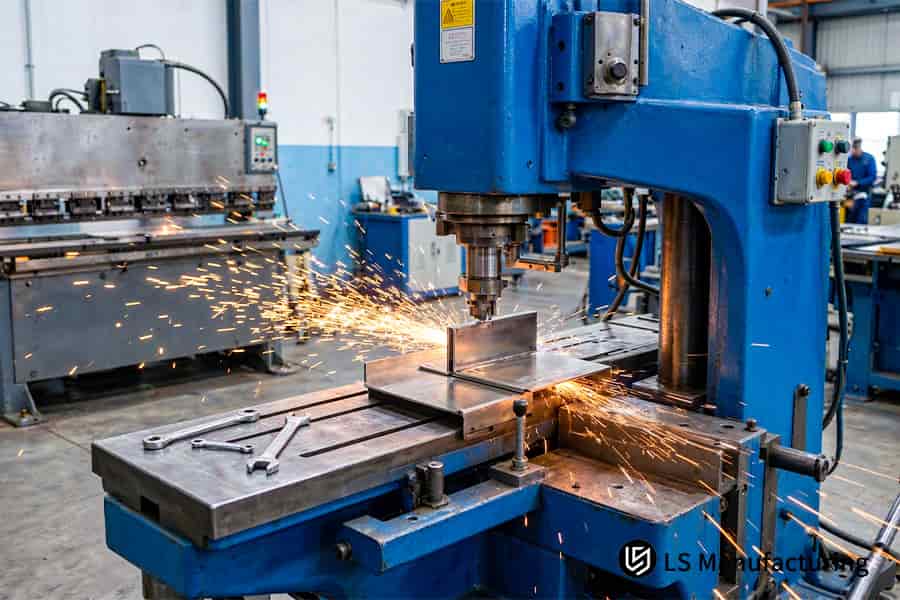
Figure 2: Hydraulic press forms sheet metal using DFMA guidelines at ±0.03 mm.
When Should Engineers Consolidate Multi-Piece Sheet Metal Enclosures?
Multi-piece consolidation is sheet metal design technique folding ribs, rail brackets and cable channels in a single unfolded blank. Interior brackets define consolidation window. Loose brackets increase part numbers and floor hours. One multi bend operation folds external brackets into the main frame. Consolidated blanks eliminate secondary fastening and spot welds. Inventory reduces by 40%.
Consolidation Decision Matrix
Sheet metal bracket design reviews open when loose ribs and rail brackets crowd one enclosure interior. Each rule below maps one enclosure condition to one merge decision and one floor result.
- Interior ribs built as loose pieces → Form ribs into the main blank → Rib bolts and rib handling leave the build.
- Rail brackets bolted to side faces → Fold brackets into the frame → Bracket alignment and spot-weld steps vanish.
- Cable channels carried by add-on hardware → Press channels into the floor panel → Channel fasteners and one part number disappear.
- One frame listing 12 separate pieces → Restructure into 4 bent bodies → Mismatch from batch variation stops.
Sheet metal assembly design creates brackets as formed-in features. No need to locate brackets anymore, and your purchase order will contain less lot numbers.
Custom sheet metal assembly service provides your team with one bent body part instead of loose parts. Assembly workstations no longer need bin picking, which results in shorter queue at joining workstation.
Sheet metal part count per frame gives you an idea about merge return period. Less part numbers mean that variability is harder to escape, and your cabinet cost remains unchanged when lots change.
Simply put, formed brackets do the locating that loose hardware once charged to your crew. Buyers who reduce sheet metal assembly cost delete joining steps before negotiating hourly rates.
How To Fix Assembly Misalignment Caused By Thermal Weld Distortion?
Heat distortion control is a weld joint design technique that controls heat input during the drawing phase and allows for hole spacing accuracy without the need for post-weld straightening. Heat relief slots and self-locking slots take place of continuous welds. Post-weld chassis dimensions will be within tolerance range. Hydraulic straightening will remain in your process.
Which Weld Layout Cuts Heat Input
Stitch welding (beads that are separated by spaces) minimizes arc-on time for all enclosures. Buyers asking how to fix assembly misalignment gain more from seam layout changes than from press tonnage. Custom sheet metal enclosures have stitch pitch specified prior to tooling release.
| Weld layout | Heat input | Post-weld correction | Effect on your floor |
| Continuous full seam | Concentrated | Hydraulic straightening | Extra press route per cabinet |
| Stitch weld + self-locking tabs | Distributed | None | Hole pitch stays in band |
| Thermal relief notches at corners | Released locally | None | Second stress-relief step deleted |
Stitching layouts reduce the total thermal deformation to 75%, eliminating the stress relief operation for your project. Continuous MIG weld joints concentrate the arc energy in just one joint. Drift in the hole pitch happens after cooling.
Seam locations away from datum faces ensure constant hole spacing. Post-weld enclosures can maintain precision sheet metal fabrication tolerances without a straightening step. Datum feature shift is covered by ASME Y14.5-2018 Chapter 7.
Sheet metal assembly design with seam offset makes the press station obsolete. Sheet metal weld fixtures is no longer required after the tabs take the panel alignment. In plain terms, seam placement performs the straightening your press once billed to your project.
Data source: ASME Y14.5-2018 Dimensioning and Tolerancing standard (Chapter 7, datum feature and profile tolerance specification).
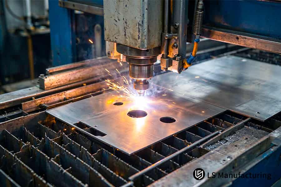
Figure 3: Laser cutting sheet metal fixes assembly misalignment within ±0.01 mm.
Behind The Numbers: Practical Experience From LS Manufacturing Experts
Gloria, Rapid Prototyping & Rapid Manufacturing Specialist at LS Manufacturing, has over 15 years of experience in machining and DFM (Design for Manufacturability) optimization. Verify Gloria's DFM & Manufacturing background. Your enclosure designs get bend-friendly geometry prior to tooling fabrication.
ASTM material specification provides the minimum inside bend radius for cold-rolled steel and 5052-H32 aluminum in your parts assembly. A CMM laboratory with sub-micron volumetric measurement error certification for the formed panels, and your incoming inspectors have the measurements traced to calibrated metrology equipment.
AWS D9.1/D9.1M (sheet metal welding code) defines weld joint acceptance criteria in the cabinet frames. A chief structural process director checks bend and fastening criteria according to ISO 9001:2015 procedure. First hand rules cover more than 1,200+ structural drawings categorized for 2025-2026. CAD 3D/2D upload prior to tooling release.
What Role Do Standardized Fasteners Play In Reducing Labor Cost?
Standardized fasteners are sheet metal DFMA rule that standardize a mixed array of bolts to a single thread type. Standardized hardware eliminates driver changes at every station. Clinch studs seated prior to bending allow one person to tighten them top-down using a single pneumatic driver. Cycle time can be reduced by over 20%.
How Do Standardized Fasteners Cut Station Motion
Sheet metal DFMA design guidelines include fastener quantity on the list prior to the release of the tooling.
- Combine all fasteners in the M4 — ISO 68-1 specifies the basic metric thread profile for studs and nuts. One pitch along base plates and columns allows your team to use one driver bit.
- Insert hardware before bending — Sheet metal hardware insertion installs PEM nuts (nuts that are inserted in the sheet metal without drilling a hole) in flat blanks. Panels are supplied with captive threads and bin-side sorting is eliminated.
- Thread from top using one hand — Captive threads eliminate the need for a counter-holding wrench and wrist fatigue and miss-installation opportunities. Buyers reduce sheet metal assembly cost at the specification stage.
Which Standards Keep One Driver Running
ASME B1.1-2019 Chapter 4 (thread engagement tolerance for unified and metric assembly) determines the fit class for stud runs. Wrench-free joints eliminate the reverse-hand reach in overhead operations.
Custom sheet metal assembly service workers insert panels with sheet metal pem nuts pre-assembled off-line. Unsecured washer stacks require another pick up of tools; captive nuts do not. Simply put: a single thread specification allows you to get back the time your workers spent organizing washers.
Data source: ASME B1.1-2019 Unified Inch and Metric Screw Threads standard (Chapter 4, fastener thread engagement tolerance).
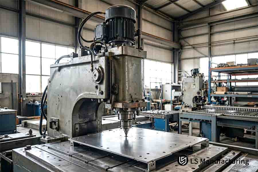
Figure 4: Forming thick sheet metal plate increases labor due to ±1.0° drift.
How Do Precision Sheet Metal Fabrication Tolerances Prevent Stacking?
Tolerance stacking is the sum of deviation from the centerline per bend in a multiple bends chain, closing the clearance of the mating hole via geometrical chaining. Holes located within the limits of precision sheet metal fabrication tolerances fall under precision grade per ISO 2768-f, and hence pins mate easily.
Which Tolerance Decisions Break The Deviation Chain
Bend centerline deviation triggers the geometric chain because each bend contributes an offset to all holes downstream. Sheet metal assembly design assessment uses datums for holes before releasing tooling. Custom sheet metal bending with bend-in-process angle measurement helps correct deviation in real time.
- ±0.03 mm of centerline offset per bend →4 bends → 0.1 mm → mating bolt holes have no clearance left.
- One datum per locating hole → chain deviation stops at the flange → hole patterns align according to one datum.
- Forming band ISO 2768-m → flange deviation remains within clearance tolerance →halves of the housing can be closed on pins.
Which Controls Keep Pins Entering Freely
Asking how to fix assembly misalignment problems buyers benefit more from decoupling hole datums than from increasing clearance. Dynamic laser angle measurement (angle feedback during the cycle of the bend) measures flange angle while bending. CNC correction corrects the drift prior to the final bend.
Sheet metal press brake service crews log every measured angle. Incoming inspectors measure one datum per hole. Manual press brake can not retain datum chain, because human eyeball introduces one offset per bend. One datum per hole eliminates hand-fitting operation from your floor.
Case Study: LS Manufacturing Custom Sheet Metal Assembly Service For Industrial Automation Robot Cabinets
Custom sheet metal assembly service is used to consolidate loose stamped panels into formed bodies, what makes possible to compensate for cumulative tolerance drift using tab-and-slot self-fixturing. Tab-and-slot joint maintains precision fit band according to ISO 2768-m/f standards. Total assembly labor cost falls 31.6% per cabinet. Direct assembly hours account for 28.4% of that reduction — your fitters stop prying panels straight — while rework dropping from 14.2% to 2.1% and eliminated fixture setup supply the rest.
Client Challenge
Robot drive cabinet of an automation integrator in Europe comprised 19 distinct panels and angle steel brackets. Four hex bolts sizes and uncontrolled cumulative deviation resulted in manual prying. Time per cabinet fell from 280 to 191 minutes on the robot cabinet line (68.2% of baseline); across the full 1,200-cabinet dataset, assembly time averages 68.4% of baseline.
LS Manufacturing Solution
Sheet metal assembly design review (Design for Manufacturability – DFM) began within two hours after receiving CAD drawings. Consolidation involved merging the distinct panels into seven formed sections connected by tabs and slots. First article bending trial distorted datum panels due to internal stress relaxation. Laser anneal relief cuts at 1.5 mm and change in punch-die sequence minimized springback. Key mating holes were finished burr-free.
Results and Value
Time taken per cabinet was reduced to 191 minutes. Rework was lowered to 2.1%, which stopped stripped threads and face scratch. Batch lead time was reduced to 10 days, which is a 37.5% improvement. Cost per cabinet went down on the consolidation route in a double-digit percentage, which allowed buyers to reduce sheet metal assembly cost before volume release. Zeiss CMM (Coordinate Measuring Machine, volumetric error of 0.0009 mm) validated the first article under AS9100D and ISO 9001:2015.
Sheet metal fabrication were accepted during the fit-up phase without shimming. A supervisor in Europe, who was responsible for integration, stated, "Cabinets were dropped into our electrification line without any adjustments at all, so we didn't do any alignments."
Data source: LS Manufacturing automation sheet metal production review log (project #AUTO-2026-882, sample size >1,200).
Upload STEP, IGES, or PDF drawings and reference project #AUTO-2026-882. A DFM engineer returns marked-up drawings with the datum scheme, tab-and-slot callouts, and fastener consolidation already mapped out — plus a first-article inspection plan built on the same Zeiss CMM routine used on this build.

FAQs
1. What are the best tolerances for precision sheet metal fabrication?
LS Manufacturing controls laser dimensions to the ISO general tolerance system and mating slots to the ISO 2768-2:1989 precision fit tolerance band. Inspection teams receive panels that pass go/no-go gauges on the first attempt. Dock-to-stock queues become smaller. Engineering teams comparing sheet metal parts to machined parts will have one more written acceptance criterion in their purchase orders.
2. How does material selection affect sheet metal assembly design?
ASTM A1008/A1008M-23 cold rolled steel and 5052-H32 aluminum according to ASTM B209-21 have different springback coefficients. At LS Manufacturing, the minimum inner bend radius equals 1 × sheet thickness to prevent cracking of the outer fiber. Assembly teams receive flanges without hairline cracks, and bending cannot be redone in the welding cell.
3. Can tab and slot designs replace full-seam structural welding?
Self-locking tenons take joint shear before arc welding commences, while intermittent spot welding per AWS D1.3:2018 restores 100% of the full-seam rated capacity. OEM production lines maintain structural integrity while reducing the lengths of continuous bead welding. Tab-and-slot design in project #AUTO-2026-882 mounted robot drive cabinets with load testing without using straightening presses. Prototype orders involve no minimum order quantity because tabs fit in the same laser cut sequence.
4. How does LS Manufacturing ensure rapid prototype delivery?
LS Manufacturing provides DFM feedback within 2 hours of receiving CAD drawings and arranges automated in-house production lines for that same day. Project planning reduces the time for prototyping the chassis by 37.5%, bringing it down to 10 days. CAD drawings remain protected under a signed NDA (non-disclosure agreement) throughout the entire review process.
5. What surface finish is maintained on laser-cut assembly tabs?
Nitrogen-fiber high-power laser cutting and vibratory grinding finish tab edges to machined standards per ASME B46.1:2019 without any dross. No warranty claims have been made due to scratched mating faces after implementing edge finishing on the drawings. Nitrogen laser cutting prevents oxide layer formation on the surface before powder coating.
6. What hardware standardization is recommended for DFMA enclosures?
PEM (self-clinching) standard studs have M4 × 0.7 thread according to ISO 965-1:2013, and LS Manufacturing presses them into blanks prior to bending. Purchasing staff controls just one line of fasteners rather than a combination of washers and bolts.
7. How to prevent sheet metal assembly misalignment in thin plates?
Stamped ribs make sheet rigid, while self-guiding bevels guide mating edges to a 10 μm fit without assembly tools. ASTM A653/A653M-23 standard applies to the zinc-coated sheet utilized in these parts. Quality audits measure compliance by aligning against a single reference point rather than multiple stacked references. Customers monitoring sheet metal repair costs eliminate the step that damages cosmetics panels.
8. Why Choose Custom Sheet Metal Assembly Service from LS Manufacturing?
LS Manufacturing holds aerospace-level quality certification and closes every first article through a Zeiss CMM inspection loop. Capital budgets record a documented double-digit cost reduction per cabinet from drawing optimization through assembly delivery. A sheet metal assembly quote request begins with one 3D file and returns a firm price. Auditors gain a documented inspection trail for every production run.
Summary
Quality sheet metal assembly begins with 3D CAD drawings that incorporate bends and interlocks that cannot be misaligned in assembly. Your plant can begin producing volumes of your part without weld jigs or press straightening, thanks to DFMA-verified drawings. Our certified quality management processes, sub-micron capabilities, and Zeiss CMM measurements ensure each incoming part is subject to just one acceptable standard.
Tighter drawing tolerances and increasing assembly time do not have to stop your new chassis from launching. Use the Quote button to send your 3D/2D CAD drawings — you'll get marked-up drawings with the datum scheme and tab-and-slot callouts, a line-by-line quote, and the full inspection package (FAIR, material certifications, dimensional reports) before you commit to volume. You will get process reductions and quote information in each report.
📞Tel: +86 185 6675 9667
📧Email: info@lsrpf.com
🌐Website: https://lsrpf.com/
Disclaimer
The contents of this page are for informational purposes only. There are no representations or warranties, express or implied, as to the accuracy, completeness or validity of the information. It should not be inferred that a third-party supplier or manufacturer will provide performance parameters, geometric tolerances, specific design characteristics, material quality and type or workmanship through the LS Manufacturing network. It's the buyer's responsibility. Require parts quotation. Identify specific requirements for sections. Please contact us for more information.
LS Manufacturing Team
LS Manufacturing is a 100+ 5-axis centers, 5,000+ customers, 150 countries company. Focus on custom manufacturing solutions. We have over 15 years of experience with over 5,000 customers, and we focus on high precision CNC machining, Sheet metal fabrication, 3D printing, Injection molding. Metal stamping, and other one-stop manufacturing services.
Our factory is equipped with over 100 state-of-the-art 5-axis machining centers, ISO 9001:2015 certified. We provide fast, efficient and high-quality manufacturing solutions to customers in more than 150 countries around the world. Whether it is small volume production or large-scale customization, we can meet your needs with the fastest delivery within 24 hours. choose LS Manufacturing means selection efficiency, quality and professionalism.
To learn more, visit our website: www.lsrpf.com

