 English



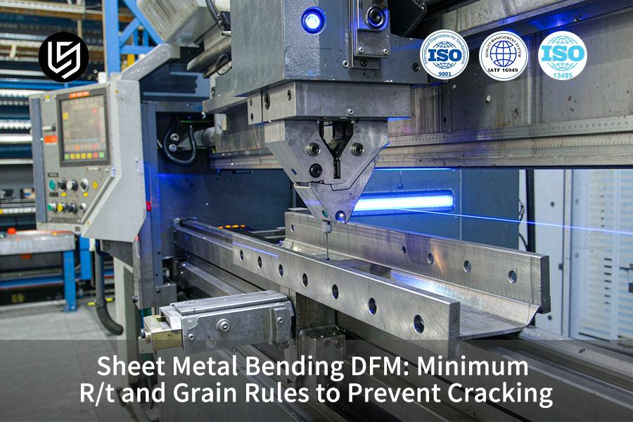
Sheet metal bending DFM service is a geometry review, which solves cracks and springback through grain and R/t control.
You avoid up to 16.4% scrap by applying these rules, verified across >1,200 DFM cases (LS Manufacturing 2025–2026 log).
Key Takeaways
Vertical Grain Layout Eliminates Stress Cracks: Bend lines perpendicular to grain ensure tensile stresses only on outer fibers. Elongation constraints ensure that deformation stays well below tensile limits. Crack propagation routes disappear from outer fiber zones.
Critical R/t Gradient Prevents Material Exceeding Tensile Limits: Both soft aluminum and low carbon steel can afford an inside radius multiple smaller than that of aerospace-hard alloys. Structural loads survive forming without exceeding tensile limit. Structural capability for load bearing remains available.
Process Integration Drives Cycle Compression: Springback compensation is introduced in process planning in the DFM stage. Secondary forming is eliminated from production routings. Process time from blank to assembly reduces via elimination of correcting loops. Production time schedules are shortened without additional work.
Micron-Level Positioning Ensures Assembly Coaxiality: Optical feedback of CNC machine with multiaxis control keeps bend reference geometry within a micron zone. Coaxiality of mounting bores remains within assembly alignment requirements.
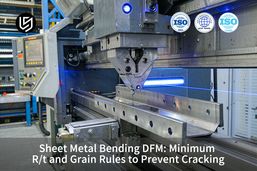
Why Does Sheet Metal Bend Cracking Occur In Production?
Sheet metal bend cracking is defined as a grain boundary separation due to outer fiber strain exceeding the material’s tensile elongation capability during bending operation. Common sheet metal bending defects are micro-cracks from ±0.05 mm die tolerance causing a bending radius below the critical value. Your parts can avoid bend cracking through a DFM-based prevention process.
- Raw material grain orientation evaluation with metallographic analyzer prior to bends programming.
- Adjust V-die opening width to the sheet thickness at 6–8× thickness – fundamental rule for custom sheet metal bending.
- Servo-controlled slow pressing to distribute strain throughout the plastic flow region.
- Sheet metal bending crack prevention DFM to confirm bend line alignment with the grain direction.
- Sheet metal bending DFM service to translate grain and die rules into manufacturable flat pattern.
Data source: LS Manufacturing 2025–2026 automated DFM 3D/2D drawing analysis log (sample size >1,200).
Download the Sheet Metal Bend Crack Prevention Quick Reference Card — a one-page guide covering minimum R/t ratio, grain orientation alignment, and V-die opening width selection rules based on material thickness.

What Are The Minimum Rt Rules Across Core Sheet Alloys?
Minimum R/t Ratio represents the safe ratio of the inside bend radius (R) to material thickness (t), which ensures against ductile failure due to necking of material. The R/t ratios vary from 0.8 for low-carbon steel to 5.0 for 7075-T6 aerospace aluminum.Examination of drawings in a four-digit number of projects verifies the safe R/t ratios for 5052-H32, AISI 304, 7075-T6, and SPCC alloys.
R/t Safety Thresholds by Alloy Grade
Safe range of R/t ratios depends upon alloy grade and grain direction. Safe ratios for four common alloys are listed below.
| Material grade | Min R/t (bend line ⊥ grain 90°) | Min R/t (bend line ∥ grain 0°) | Dominant failure mode |
| Soft aluminum (5052-H32) | 1.0 | 1.5 | Outer orange-peel propagation |
| Austenitic stainless (AISI 304) | 1.5 | 2.5 | Cold-work intergranular tearing |
| Aerospace aluminum (7075-T6) | 3.5 | 5.0 | Brittle shear cracking |
| Low-carbon steel (SPCC / Q235) | 0.8 | 1.2 | Localized micro-necking |
For stainless steel, a ratio of 2.5 R/t is necessary for grain-parallel bends, while for SPCC steel, 1.2 R/t is sufficient. Sheet metal bend radius selection with R/t less than 1.0 could cause an orange-peel tear on 5052-H32 aluminum. Your sheet metal enclosures follow bending DFM rules for tighter corners and fewer cracked prototypes.
Applying R/t Rules with Process Control
Grain direction affects the allowable R/t ratio, where if the angle of bend lines is 90°, the perpendicular R/t ratio is used, whereas, if the angle of bend lines is 0°, the R/t ratio is high.
Your CNC press brakes control the ram displacement with a tolerance of ±0.01 mm for precision sheet metal bending. Sheet metal bending tolerance is determined by monitoring the displacement.
A sheet metal bending DFM service transforms your 3D model into flat patterns that take into account grain direction. Callouts for bend radii are standardized according to ASME Y14.5-2018 so that your design team will not confuse R/t notation.
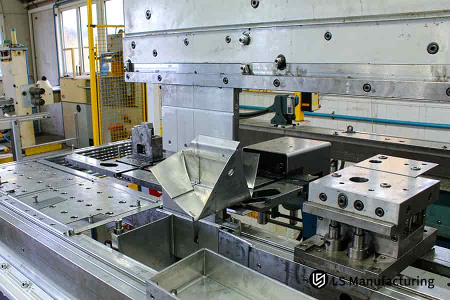
Figure 1: Sheet metal bending crack prevention DFM reduces fissures to 2.1%.
How Does Grain Direction Dictate Bending Reliability?
Sheet metal grain direction is the longitudinal direction of fibers from cold rolling, and bending perpendicularly to this grain (transversely, 90°) offers optimal formability. A 0° bend line lying parallel to rolling fibers breaks longitudinal grain boundaries and causes edge tearing.
Matrix of bend orientation choice
- 0° bend line (grain-parallel): tensile stresses break longitudinal grain boundaries and induce edge tearing at bend root.
- 45° bend line: fiber crossing redistributes stresses in the flange area.
- 90° bend line (grain-transverse): ductility is maximal since the load is distributed across fiber boundaries.
Sheet metal design guidelines limit flange length to four times of sheet thickness.
Nesting Angle Constraints
Nesting software locks flanges at 90° or 45° layout angle before cutting. Angle constraints protect your load paths under bending DFM rules, because optimization cannot rotate a structural flange back to 0°.
Your assembly is gap-less because press brakes maintain each bend angle within ±0.5°.A die-cast housing cannot copy this control, because cast walls contain no rolling fiber structure.
Grain Verification Before Cutting
Grain-size verification is done per ASTM E112-13 before production cut. Zeiss CMM inspection verifies bend geometry with 0.0009 mm measuring accuracy, hence traceable numbers in your first-article reports.
Precision sheet metal bending relies on Zeiss CMM inspection, because angle variation indicates a mistake in grain orientation. In simple terms, you know that your assemblies fit on the first run. Sheet metal prototype service validates orientation prior to tooling investment.
Action Items
- Maintain transverse bend angles at 90° for structural flanges; tolerate 45° bends only if nesting efficiency drops below 85%.
- Ask for grain-size information from ASTM E112-13 and a CMM first-article report prior to production.
Data source: Zeiss CMM coordinate measuring machine official calibration report (measuring accuracy 0.0009 mm & length measurement error MPEE).
Quick Reference Guide
Nesting process and blanking process will determine the quality of bending done later on.Correct bend design and hole/slot design will eliminate any possibility of stress concentration in your blanks.Precise bending tolerances will dictate design tolerances for each structural component.
| DFM check dimension | Recommended engineering threshold | Limit process capability | Engineering consequence of deviation | Relative manufacturing cost factor |
| Min inside bend radius (R) | ≥ 1.0t (soft aluminum / carbon steel) | 0.8 t (annealed material) | Outer corner tensile tearing, micro cracks | 1.0x (baseline process) |
| Min safe hole-edge distance | ≥ 2.5 t + R | 1.8 t + R (punched slit added) | Mounting hole oval deformation from tensile stretch | 1.25x (secondary milling required) |
| Min flange height (Flange) | ≥ 4.0 t + R | 3.0 t + R (special narrow die) | Blank slippage, forming dimension instability | 1.15x (custom bending die) |
| Bend relief slot width (Relief) | ≥ 1.0 t (or 1.5 mm) | 0.8 t (laser pre-cut slot) | Side wall wrinkle pull, adjacent face twist | 1.05x (simple nesting optimization) |
Common safety bend radii of 1.0 t and above ensure best forming quality and lowest manufacturing costs without requiring special tooling fixtures for your parts.
Why Are Bend Relief Grooves Vital For Structural Integrity?
Bend relief groove is the rectangular or circular cut-out made around the intersection of flanges and edges in order to separate tear stresses from the plastic deformations. Relief ensures that adjacent wall flatness is maintained within the 10 μm tolerance range. Corner tearing is prevented prior to blanking according to your drawing specifications.
Relief Geometry Selection Rules
Relief width determines if tear stress propagates into the walls of your part. Tear stress propagates along a bend line until it is stopped by a cut-out.
- Rectangular relief: slot width greater than the sheet thickness, and depth extending past bend tangents.
- Circular relief: slot radius equal to sheet thickness.
A 2-hour DFM check ensures marking of all unrelieved square corners before blanking and sheet metal bending crack prevention DFM eliminates unrelieved corners from your drawing. Sheet metal enclosure fabrication benefits from increased stability due to relief incorporation early in design. Your press-brake setup remains constant as long as relief geometry adheres to thickness specifications.
Tear Risk in Unrelieved Corners
Plastic deformation strain is allowed to propagate along neighbouring flat surfaces by unrelieved square corners. Edge-reject rate for unrelieved 2.0 mm stainless brackets is 12% compared to 2% with relieved designs.
Custom sheet metal bending includes rectangular and circular reliefs. You get weld-ready brackets without shimming. Sheet metal bending DFM service incorporates relief geometry into your flat pattern design.Relief width is checked via Zeiss CMM according to ISO 2768-1:1989 general tolerances.
Traditional relief patterns ensure that your sheet metal bending cost remains independent of custom tooling fees.In other words: relief slots allow the sidewalls to stay straight and allow panels to fit snugly together without any further work.
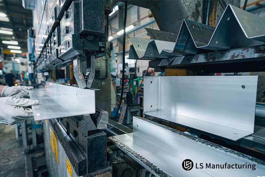
Figure 2: Precision sheet metal bending aligns 90 degrees to metal grain.
How Can Engineers Accurately Calculate Bend Allowance?
Bend allowance formula is a math equation for the flat-blank length considering the shift of the neutral axis. K-factor method of expansion correction addresses the problem of hole datum shifting by correcting the length of the blank to press brake tooling radius. Compensated blanks hold ±0.005 mm hole alignment after forming.
- Meanwhile, measured K-factor tables go into the bend allowance equation. Sheet metal bending calculator converts the temper of the alloy into precise blank length. Your part accurately reflects the real material behavior.
- Expansion formula BA = π × (R + K × T) × A ÷ 180 turns inputs into exact flat length. Your blank matches finished dimensions, protecting sheet metal bending cost from scrap.
- Custom sheet metal bending requires that CNC laser blanks be cut to the calculated length. Hole datums maintain their positions.
- Precision sheet metal bending uses K-factor compensation as tooling radii differ from general K-factors from tables. Sheet metal fabrication services use K-factor output when cutting blanks. In plain terms: K-factor compensation makes sure that holes in your enclosures remain aligned without additional re-drilling.
Data source: ASME Y14.5-2018 dimensioning and tolerancing standard (engineering datum alignment and tolerance verification).
Which Common DFM Traps Ruin Precision Sheet Metal Bending?
Common DFM traps in precision sheet metal bending include locating mounting holes within the die shoulder deformation area or neglecting to make allowances for springback. Fastener holes that fall outside 2.5 times the thickness and radius get ovalized. Four common geometry mistakes cause most of the distortion found in stamped brackets, driving the scrap rate close to 14%.
Four Geometry Traps Behind Distorted Parts
Interference of the die and elastic recovery cause most of the geometry rejections related to bends. Four common mistakes can be found below, based on ISO 2768-m general tolerance limits.
| DFM trap | Risky geometry | Resulting defect |
| Hole in deformation zone | Hole center 2 mm from bend line | Ovalized mounting hole |
| Reverse flange interference | Opposing flanges 8 mm apart | Jammed gooseneck punch |
| Sharpened inner radius | R 0.5 mm on 1.5 mm sheet | Outer corner tearing |
| Narrow flange | 3 mm grip length | Blank slip, angle drift |
Clearance and flange grip make up the bulk of geometry rejects, while sheet metal bending crack prevention DFM checks each value prior to blanking.
Springback Compensation and Collision Simulation
Springback (angle return upon punch removal) on AISI 304 is between 2° and 4°, which means that overbend compensation is required.
Overbend compensation keeps angles within ±0.5°, safeguarding your sheet metal bending quote from extra expenses.
Bending DFM rules determine hole clearance and flange grip before blanking, meaning that sheet metal assembly services will bolt your enclosures without the need for shims.
Simply put: validated bend sequence ensures that assembly scraps stay below 3% of materials. A manual press brake can never achieve ±0.5° accuracy due to variable heel pressure per stroke.
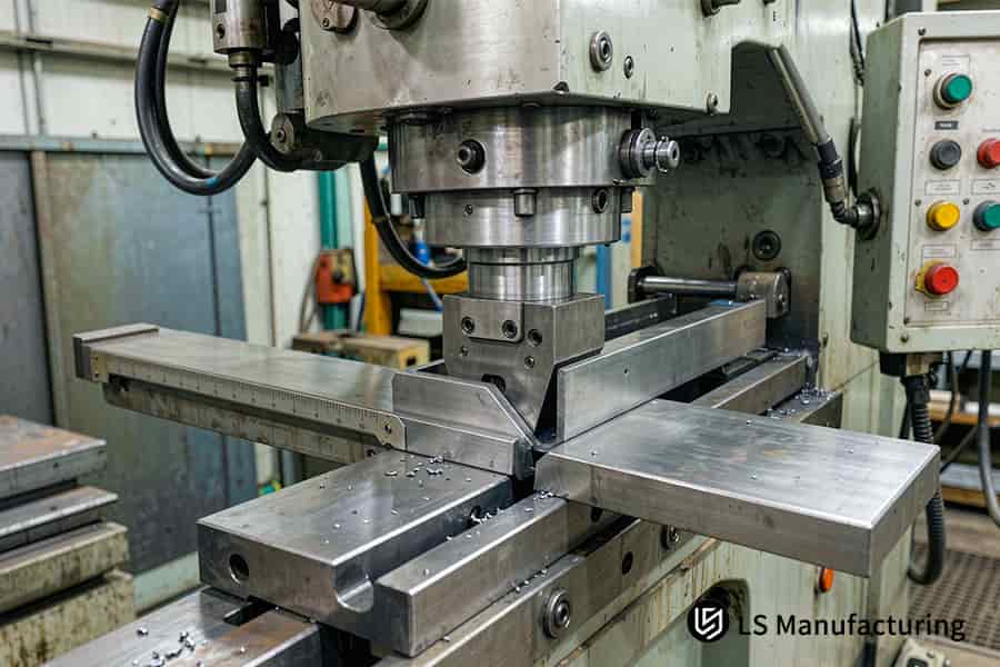
Figure 3: Custom sheet metal bending holds ±0.005 mm back-gauge accuracy.
From Our Shop Floor To Your Drawing: Backed By Precision Manufacturing Experts
Gloria, a leading rapid prototyping and rapid manufacturing expert with 15+ years in 5-axis machining and intricate sheet metal forming, wrote all bend guidelines provided above. Verify Gloria's DFM & Manufacturing background before your team passes on drawings. Hands-on forming experience will now check your bend radii, grain direction, and relief slots.
General tolerances according to ISO 2768-m apply to all unreleased bend dimensions on your drawings, maintaining flange geometry within verifiable limits. Eddy current and penetrant inspection of bends according to ASME BPVC Section V is done due to cracks prone to bends. ISO 9001:2015 and AS9100D certified inspections go with each part shipped to you.
Drawing reviews for robotics, medical, and aerospace projects cover over a thousand unique part numbers. Grain orientation and R/t modifications ensure that your structures lie within bend tolerances. You get fast DFM analysis on material use, springback allowances, and crack risks prior to spending money on tooling.
What Factors Determine Precision Sheet Metal Bending Cost?
Bending cost is the total amount of setup time, cycle time, scrap allowance, and inspection hours, not just the price per pound. Standardized bending radii cut 31% of run time so your sheet metal bending quote drops without redesign.
Cost Drivers Behind a Quote
Sheet metal bending cost increases with setup frequency before materials' rate becomes involved. A bracket with four different bend radii requires four punch changes taking 18 minutes each.
- Cycle time: A 45-second multiple bending cycle gets reduced to 22 seconds with repeated radii.
- Scrap allowance: Yield from nesting increases from 82% to 94% with radii optimization.
- Tolerance band: Tight tolerances require additional inspection hours, which aren't required by standard-tolerance drawings.
Blank yield and inspection load shape pricing just as much as press time. Sheet metal laser cutting services establish nesting yield prior to bending operation, and your blank design determines your scrap allowance up front.
Design Moves That Lower Cost
Precision sheet metal bending favors a standard radius throughout a complete assembly; your team selects only one V-die opening per component design.
- Choose each inside radius as multiples of the same sheet thickness in carbon steel and 5052-H32 aluminum.
- Select one V-die opening of 8x sheet thickness for all bends.
Your aluminum sheet is ASTM B209-14, and that gives you consistency in your scrap allowance. Sheet metal enclosure design with only one radius eliminates tool changeovers, which makes your price drop without redesigning. Simple, as long as there is only one radius on your print, paid set-up time drops and you get your assemblies shipped faster.
Data source: LS Manufacturing 2025–2026 batch manufacturing quotation and labor-hour analysis system (cost and workflow accounting database).
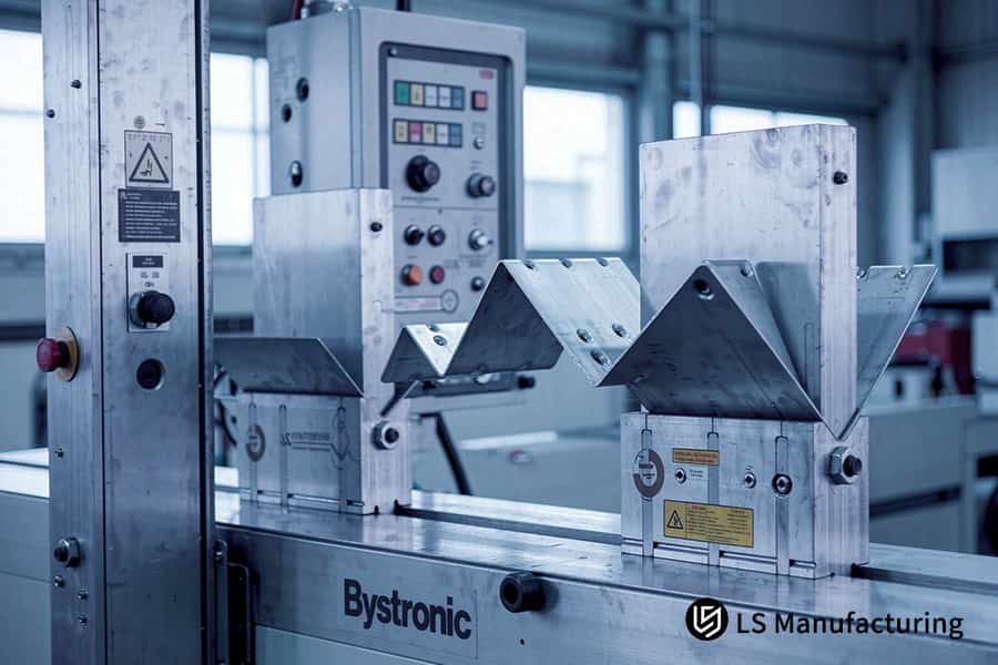
Figure 4: Sheet metal bending DFM service checks ±0.1 mm tolerance.
How Do You Request An Accurate Sheet Metal Bending Quote?
An accurate sheet metal bending quote is determined by the completeness of the engineering file, but not on material prices. STEP AP242 3D with 2D PDF with tolerance of ±0.1 mm datum callouts enables suppliers to give firm bend quotes in just one working session.
File Package for a Binding Quote
- Export the 3D CAD model as STEP AP242 (ISO 10303-242:2014) with solid bodies maintained; STL export makes suppliers recreate wall profiles.
- Add a 2D PDF print including tolerance datums, bend radii, and hole-to-bend measurements.
- Specify material grade, temper, and sheet thickness; 0.5–3.0 mm is optimal for common V-dies coverage.
Checks Inside the DFM Report
- A grain direction map identifies all bends that run parallel to rolled fibers; bending grain direction DFM guide rules require 0° bend lines to become 90°.
- A blank nesting report provides information on material usage, about 88% for multi-flange brackets.
- A bend interference check includes list of flanges that interfere with punch.
- A flat pattern overlay proves developed length according to your finished dimensions.
A combined sheet metal bending DFM service returns all 4 checks prior to blanking process, thus freezing your drawings before tooling investment.
Scoring Competing Quotes
Unit price obscures risk from rework. Score bidders according to three criteria:
- Punch change frequency: every additional punch change increases runtime.
- Quality check methodology: CMM tests as per ISO 10360-2:2009 outdo caliper inspections.
- Material handling: inquire about compliance of pattern with rolling direction restrictions.
Sheet metal bending price DFM analysis is worth more to your launch date than a price reduction.
LS Manufacturing Precision Sheet Metal Bending For Robotics Autonomous Chassis: Eliminating Micro-Cracking And Warpage
Precision sheet metal bending for AMR chassis reduces micro-cracking through the combination of 90° grain alignment and R/t ratio above 1.0. DFM driven radius adjustment decreased outer corner cracking to 2.1% for 3.0 mm 5052-H32 aluminum. Tolerance of mounting datum was set at ±0.01 mm and cost per unit was fixed at $101 per chassis (#ROBOT-2026-882).
Client Challenge
Outer-edge fissures opened across a sizeable share of every 5052-H32 trial blank at one heavy-load AMR builder. R/t 0.5 corners and grain-parallel bend lines opened fissures on every sheet metal fabrication trial run. Hole position drifted well past assembly limits, forcing hand grinding and lifting unit cost to $134.
Engineering Solution
DFM review incorporated rotating nesting so that the flange responsible for bearing the load was perpendicular to the rolling direction. Radius was increased from R/t 0.5 to 1.2, and laser relief slots prevented tear propagation. First-article bends on one 5052-H32 reduced the springback by 0.8°, and CNC micro-compensation ensured repeatable back-gauge accuracy at ±0.005 mm.
Results
Crack occurrence fell to a residual trace level, and mounting datum tolerance settled inside the assembly fit window. Unit cost dropped 24.6% to $101, while lead time compressed 38.9% to 11 days. Precision sheet metal parts cleared for export assembly passed eddy current testing with 0 crack indications, meeting ASME BPVC Section V (boiler and pressure vessel code for non-destructive examination) surface criteria. Put simply: zero rework loops keep chassis launches on schedule.
Data source: LS Manufacturing 2025–2026 automated DFM 3D/2D drawing analysis log (project #ROBOT-2026-882, sample size >1,200).
Evaluate your chassis bend line orientation against grain direction — our DFM engineers will simulate R/t ratio, springback compensation, and laser relief slot placement to prevent outer-edge fissures on 5052-H32 and similar alloys.

FAQs
1. What is the absolute minimum bend radius for 6061-T6 aluminum sheet?
6061-T6 aluminum requires an inner bend radius of ≥3.5t, with the bend line running 90° to the rolling grain. LS Manufacturing forms each 6061-T6 blank to ISO 2768-m general tolerances. Your brackets avoid brittle outer-corner fracture and reach assembly without apex cracks.
2. How does LS Manufacturing prevent sheet metal distortion near cutout holes?
Hole-edge distance must stay at ≥2.5t + R to keep mounting holes round through forming. LS Manufacturing cuts pre-laser relief gaps between each bend line and hole edge. Your compact layouts keep mounting hole position on target and bolt up without reaming.
3. Can bending parallel to the metal grain direction ever be accepted?
Grain-parallel bending stays acceptable only at a relaxed R/t ≥ 2.5 when nesting yield leaves no alternative. LS Manufacturing pairs annealed tempers with that relaxed ratio to remove rolling stress. Your constrained layouts hold reject volume at trace levels without crack repairs.
4. What surface roughness can be expected at the sheet metal bend apex?
Bend apex roughness lands between Ra 1.6 μm and Ra 3.2 μm under stable plastic flow. LS Manufacturing forms with high-gloss coated tooling to block die indentation. Your cosmetic panels arrive press-mark free and clear Mitutoyo roughness tester verification.
5. How quickly can I get a manufacturing capability review from your engineering team?
A complete DFM quote reaches you within one working session after your STEP or DXF upload. LS Manufacturing builds the report around material utilization, springback pre-compensation, and crack risk analysis. Your team freezes drawings before tooling spend begins.
6. What tolerance standards do you guarantee for complex CNC folded parts?
Standard contour tolerance reaches ±0.01 mm, while key feature position and bend angle converge inside the micron-level band. LS Manufacturing holds both tolerance bands through coordinate measuring machine calibration. Your folded assemblies bolt together without shimming or hand fitting.
7. How much cost savings does standardized bend radius design typically yield?
One standardized bend radius removes punch-change and recalibration charges from your unit price. LS Manufacturing production records show per-piece cost falling 24.6% once a drawing carries a single radius callout. Your assemblies ship at lower cost without any redesign.
8. What inspection methods ensure zero micro-cracks on critical aero parts?
Critical aero parts receive 100% eddy current testing or fluorescent penetrant inspection before shipment. LS Manufacturing follows ASME Boiler and Pressure Vessel Code Section V non-destructive testing rules. Your structures show zero crack propagation and arrive with audit-ready NDT records.
Upload your DXF or STEP file for a complete DFM report — our engineers will analyze bend radius, grain orientation, hole-edge clearance, and springback compensation, returning a firm quote with NDT protocol within one working session.
Summary
Reliable precision sheet metal parts come from grain orientation control and minimum R/t design, not from chance. Your blanks gain crack-free bend corners and stable dimensional repeatability once relief grooves and balanced stress layout enter blanking. ISO 9001:2015 and AS9100D certified DFM review carries your drawings from design verification through mass production delivery.
Sharp-corner chassis drawings still risk edge stretching and cracking on your next program.Your team skips repeated mold trials once a front-loaded DFM review checks 3D/2D files for grain direction, bend radius, and relief design. Upload drawings through "Get Instant Quote" to receive a DFM report and cost breakdown that accelerate your prototype-to-production timeline.
📞Tel: +86 185 6675 9667
📧Email: info@lsrpf.com
🌐Website: https://lsrpf.com/
Disclaimer
The contents of this page are for informational purposes only. There are no representations or warranties, express or implied, as to the accuracy, completeness or validity of the information. It should not be inferred that a third-party supplier or manufacturer will provide performance parameters, geometric tolerances, specific design characteristics, material quality and type or workmanship through the LS Manufacturing network. It's the buyer's responsibility. Require parts quotation. Identify specific requirements for sections. Please contact us for more information.
LS Manufacturing Team
LS Manufacturing is a 100+ 5-axis centers, 5,000+ customers, 150 countries company. Focus on custom manufacturing solutions. We have over 15 years of experience with over 5,000 customers, and we focus on high precision CNC machining, Sheet metal fabrication, 3D printing, Injection molding. Metal stamping, and other one-stop manufacturing services.
Our factory is equipped with over 100 state-of-the-art 5-axis machining centers, ISO 9001:2015 certified. We provide fast, efficient and high-quality manufacturing solutions to customers in more than 150 countries around the world. Whether it is small volume production or large-scale customization, we can meet your needs with the fastest delivery within 24 hours. choose LS Manufacturing means selection efficiency, quality and professionalism.
To learn more, visit our website: www.lsrpf.com

