English



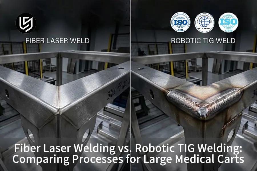
TL;DR: Though fiber laser welding offers negligible thermal distortion with a very narrow heat affected zone (HAZ) of 0.4 mm, robotic TIG welding reduces capital outlay and allows for tolerances of up to 0.25 mm in joint fitting. Breakeven occurs at 48 carts, tilting decision making towards fiber laser welding beyond this mark.
Procurement teams and mechanical engineers in the design and manufacture of reliable medical equipment enclosures commonly run into a critical point where the trade-off of aesthetic flatness versus cost becomes paramount: deciding between high-power-density fiber laser welding and TIG welding is necessary in order to weigh the pros and cons in terms of thermal energy input, tolerances, post-weld grinding, and multi-pass pieces cost per unit. Below follows a technical analysis for the decision of which mechanical joining method is feasible, as well as comparative cycle metrics and an empirical manufacturing cost analysis.
Key Takeaways
- In case the cart has elongated and slender 316L and 304 panels, then you should use fiber laser welding. Distortion and finishing will be minimal in such case.
- The appropriate choice will be Robotic TIG welding when the gap is larger than 0.25 mm and frequent change of joint path is present or when appearance follows gap bridging in order of priority.
- Take into account 48 units as economic criteria for the cart under discussion rather than the whole industry because of different weld lengths and fixtures.
- Neither process should be specified for 3.0 mm 316L joints requiring full penetration without prior welding procedure qualification (PQR) and empirical coupon testing.
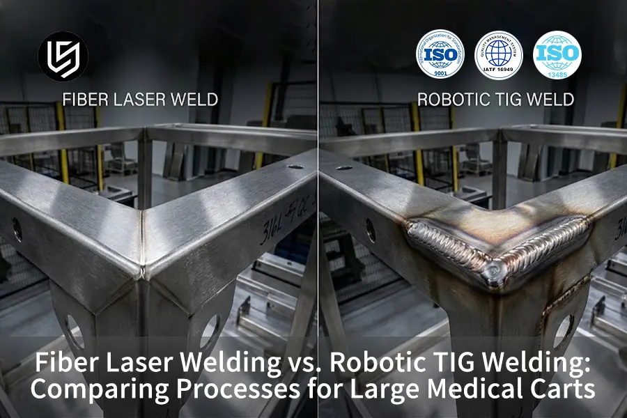
Fiber Laser vs. Robotic TIG Welding Across Critical Fabrication Thresholds for Medical Carts
The following table represents the fastest way to make a production decision that is defensible. It does not provide a definitive winner but rather the process that meets the restrictive constraint first.
|
Dimension |
Fiber laser welding |
Robotic TIG welding |
Selection threshold / recommendation |
|---|---|---|---|
|
Precision deviation, 316L 1.5 mm |
±0.12 mm |
±0.25 mm |
Below 0.15 mm envelope movement favors fiber laser welding |
|
Welded-face Ra |
Ra 3.2 μm |
Ra 6.3 μm |
Ra below 6.3 μm for visible panels favors fiber laser welding |
|
HAZ width |
0.4 mm |
2.6 mm |
Thin panels and long seams favor fiber laser welding |
|
Joint fit-up |
0.10 mm demonstrated maximum |
0.25 mm demonstrated maximum |
Gaps above 0.15 mm normally favor robotic TIG welding |
|
Welding cycle |
7.4 min/cart |
14.9 min/cart |
Runs above 48 units favor fiber laser welding |
|
Daily output |
320–420 units |
180–230 units |
High-mix capacity planning may still favor robotic TIG welding |
|
Direct unit cost, 100 pcs |
$71 |
$118 |
Calculate against cart-specific weld length and fixtures |
|
Post-processing cost, 100 pcs |
$8,400 |
$14,500 |
Cosmetics and cleaning-sensitive carts favor fiber laser welding |
The matrix demonstrates that fiber laser welding dominates in distortion, heat input and production rates, whereas robotic TIG welding is better for joint tolerances and adaptation to poor quality blanks. Therefore, evaluating fiber laser vs tig welding for medical carts begins with fit-up constraints first and batch volume second.
Why Trust Our Empirical Engineering Data?
LS Manufacturing has fiber laser welding line and robotically operated TIG welding line in its Dongguan, Guangdong manufacturing facility, with nationwide certified partners network that supports it. This comparison is meant to be neutral because the processes are recommended depending on the shape of parts, the fit-up and the order quantities.
This article was written by Gloria, Rapid Prototyping & Rapid Manufacturing Expert with 15+ Years of Precision Engineering Experience, and technically reviewed by the LS Manufacturing welding engineering department. LS Manufacturing is ISO 9001, ISO 13485 and IATF 16949 certified.
For readers to understand the author's cross-process manufacturing expertise, you can visit Gloria's Cross-Process Expertise on LinkedIn.
Which Process Delivers Tighter Tolerance for Medical Cart Enclosures?
Fiber laser welding provides the tighter tolerance result for the tested medical cart enclosure as long as the blank, bend, and fixture process ensures that the joint remains within the tight fit-up window of the laser welding process.
Tolerances achieved are fiber laser ±0.12 mm and robotic TIG ±0.25 mm in a 316L, 1.5 mm side-panel assembly. When evaluating laser vs tig welding for thin enclosures, the tolerance difference stems directly from heat input physics. Fiber laser welding focuses radiant optical energy into a sub-millimeter spot, generating a tight 0.4 mm heat-affected zone (HAZ) and mitigating cumulative angular shrinkage along long panel seams In comparison, robotic TIG welding forms 2.6 mm HAZ on the same material and thickness, leaving longer seam with more opportunity to cause movement of the panel despite proper fixturing.
The choice should take into account the entire chain of fabrication process and not simply the welding rate. It requires laser-ready blank, precise bending, edge condition control, and fixture that controls the bow and twist. Robotic TIG welding is the safer tolerance process if a change of sheet-metal is necessary to produce the joint.
- Tolerance base: fiber laser welding (±0.12 mm) and robotic TIG welding (±0.25 mm)
- Heat Affected Zone (HAZ): fiber laser welding (0.4 mm) and robotic TIG welding (2.6 mm)
- Trigger: use fiber laser welding when the envelope movement should be less than 0.15 mm
How Do Fiber Laser Welding and Robotic TIG Welding Manage Heat Distortion?
Fiber laser welding mitigates heat distortion through reduced overall heat input and small HAZ; robotic TIG welding mitigates heat distortion through pulse modulation, welding sequence and effective fixturing. According to LS Manufacturing test, fiber laser welding achieved 0.28 kJ/mm while robotic TIG welding achieved 0.72 kJ/mm.
Managing fiber laser vs tig welding heat distortion requires understanding metallurgical boundary conditions. According to the 2024 AWS Welding Journal empirical dataset on 316L stainless steel, longitudinal bending increases from 1.2 mm to 3.6 mm as linear energy rises from 0.3 kJ/mm to 0.472 kJ/mm, while carbide precipitation in the HAZ accelerates under prolonged peak temperatures.This gives the physical explanation of the boundary but cannot substitute for part-specific welding procedure. Medical carts need a proper welding sequence, balanced welding and verified fixture clearance since periphery joints tend to accumulate movement with low heat input.
The principle is to have the process match the frame condition. Fiber laser welding should be used where part design and supply chain will allow tight fit-up. Robotic TIG welding should be used where heat needs to be modulated during variable joint pathways or where existing enclosure cannot be modified for laser tolerance.
- Heating effect: fiber laser welding (0.28 kJ/mm) vs. robotic TIG welding (0.72 kJ/mm)
- Deviation of panels: fiber laser welding (±0.12 mm) vs. robotic TIG welding (±0.25 mm)
- Distortion management: low heating effect is used in fiber laser welding; pulse welding is used in robotic TIG welding
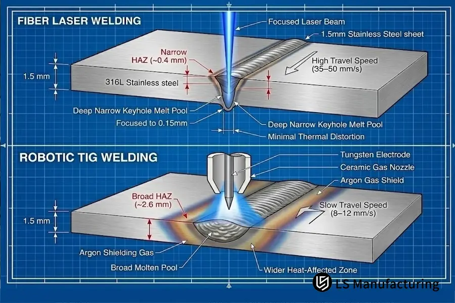
Figure 1: Thermodynamic cross-section comparison. Top: Deep, narrow keyhole profile in fiber laser welding (~0.4 mm HAZ). Bottom: Conduction-mode melt pool in robotic TIG welding with dynamic argon shielding (~2.6 mm HAZ).
Which Welding Process Is More Cost-Effective for 50 to 500 Medical Carts?
For Robotic TIG Welding process, it tends to be cost effective at around 48 carts because of absence of fixture cost. For fiber laser welding, it tends to become cost effective after absorbing the $2,250 fixture and programming cost into a long run.
A rigorous fiber laser vs tig welding cost comparison reveals that at 100 units, the LS Manufacturing measured piece price is $71 for fiber laser welding versus $118 for robotic TIG welding. This 40% unit cost advantage incorporates torch arc time, shielding gas, replacement tips, and rework labor, excluding purchased raw stock. Breakeven point can be calculated using the following formula.
Q = Tooling Cost / (Unit Price B – Unit Price A)
Q = $2,250 / ($118 – $71) = 47.87 units
From this, it equals 48 units. When analyzing robotic tig vs fiber laser welding volume, fiber laser welding's rapid 7.4-minute cycle time and reduction in post-weld surface grinding continue to compound between 50 and 500 carts. At 500 carts, the fixture burden becomes negligible relative to total production cost, allowing ongoing labor savings to dominate.
|
Quantity |
Fiber laser welding |
Robotic TIG welding |
Interpretation |
|---|---|---|---|
|
20 pcs |
$181/pc |
$118/pc |
Robotic TIG welding is cheaper |
|
48 pcs |
$118/pc |
$118/pc |
Processes reach the measured breakeven |
|
100 pcs |
$71/pc |
$118/pc |
Fiber laser welding is 40% lower |
|
500 pcs |
$37/pc |
$63/pc |
Fiber laser welding remains lower |
These numbers apply to the 316L, 1.5 mm medical cart used in the case study. A new model will be required based on new geometry, weld length, gap, and local costs before the breakeven quantity of 48 is used in a different program.
- Unit cost at 100 units: fiber laser welding ($71) vs. robotic TIG welding ($118)
- Tooling and setup: fiber laser welding ($2,250 fixture/programming) vs. robotic TIG welding ($0)
- Breakeven at 48 units in the current program
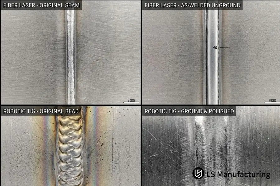
Figure 2: Macro profilometer surface study across finishing states. Top: As-welded fiber laser seam achieving an unground Ra 3.2 μm finish. Bottom: As-welded robotic TIG ripple (Ra 6.3 μm) compared with post-weld abrasive blending marks.
When Should Joint Fit-Up Determine Fiber Laser or TIG Welding?
Fit up must dictate the process choice as soon as the gap size reaches the minimum level where the laser penetration remains repeatable. LS Manufacturing's measured fit up window was 0.10 mm for fiber laser welding and 0.25 mm for robotic TIG welding in 1.5 mm 316L.
But tight fit up is not the only risk of bad fit up. Mismatch of edges, variability of the root opening size, distortions caused by previous bending and variable part presentation can all result in an unstable laser keyhole. Robotic TIG welding is able to weld using ER316/316L filler, accommodate small gaps and provide variable heat across the seam. However, this advantage comes at a price of increased cycle time and finishing cost.
The decision must start with the design stage. If fit up within 0.10 mm is achievable by laser cutting, bending and proper fixturing, then fiber laser welding is the preferred process. But if it involves too costly blank change or introduces any supply chain risks, robotic TIG welding is a better choice despite being a more expensive process per part.
|
Joint condition |
Fiber laser welding |
Robotic TIG welding |
Recommended decision |
|---|---|---|---|
|
Gap ≤0.10 mm |
Good metallurgical and cosmetic repeatability |
Slower and thermally heavier |
Fiber laser welding |
|
Gap 0.11–0.25 mm |
Requires weld trial and possibly filler laser welding |
Normal operating window |
Robotic TIG welding |
|
Mixed visible and structural seams |
Excellent cosmetic result; joint must be laser ready |
One process can cover visible and non-visible seams |
Hybrid cart route |
|
Existing enclosure with variable blanks |
Higher fit-up risk |
More adaptable |
Robotic TIG welding |
- Fit-Up Threshold: Fiber Laser Welding (0.10 mm) vs. Robotic TIG Welding (0.25 mm)
- Filler Characteristics: In fiber laser welding, it is autogenous, while in robotic TIG welding, there is the addition of filler
- Safety Measures: Test joint suitability by welding samples prior to the creation of fixtures
What Are the Feature Feasibility Boundaries Between Fiber Laser and TIG Welding?
Feasibility of features must come first since some requirements are easier to meet in terms of physical constraints in one process even if both processes have the capability of making an excellent weld.
The list below pertains to large medical carts and not abstract coupon welding.
The first 10 seconds feasibility screen is to check if the longest seams, tightest visible radii, thinnest panels, and largest gaps variability can be done without redrawing the blank and tolerances in bending. If the answer is no, split the routes per feature and not force a single process for the entire cart.
|
Feature or requirement |
Fiber laser welding |
Robotic TIG welding |
Recommended route |
|---|---|---|---|
|
Long flat visible panels |
Best thermal stability and lowest finishing |
Higher risk of cumulative movement |
Fiber laser welding |
|
Visible Class-A seams with no post-grind allowance |
Narrow weld and smaller heat tint |
Usually requires blending |
Fiber laser welding |
|
0.11–0.25 mm joint gaps |
Requires special processing |
Standard operating range |
Robotic TIG welding |
|
Frequent design changes before fixture investment |
Process-sensitive and tooling dependent |
More adaptable to program changes |
Robotic TIG welding |
|
Internal brackets and non-visible structural members |
Fast, but fit-up control is critical |
Strong gap tolerance and deposition control |
Robotic TIG welding |
|
Continuous long seam exceeding 3 m |
Low heat input preserves panel shape |
Thermal accumulation needs active control |
Fiber laser welding |
|
Hybrid cart with both classes of feature |
Best for cosmetic panels |
Best for variable joints and brackets |
Hybrid route |
The hybrid route is not a compromise but entails fiber laser welding for cosmetic and distortion-sensitive assemblies and robotic TIG welding for variable brackets and structural interfaces. LS Manufacturing produces the tested cart in this manner in order to cut down on finishing operations without making the entire system laser-ready.
As for the tested program, the hybrid route would be recommended whenever more than 40% of welded length is either non-cosmetic or has a fit-up exceeding 0.10 mm. Less than this percentage would make one laser-ready operation easier to fixturing and inspection.
LS Manufacturing Fiber Laser Welding vs. Robotic TIG Welding for Medical Imaging Cart Enclosures: 36% Lead-Time Recovery Through Process Splitting
An OEM in the field of medical imaging fabricated a 316L cart consisting of side enclosures, a base frame, brackets, and removable covers. Initially, the OEM planned to fabricate the entire cart using robotic TIG welding. The OEM required flat side panels, a cleanable surface finish and stability for the product launch.
First article parts satisfied strength requirements; however, there was an issue regarding the movement of long panel seams during welding. The robotic TIG welding resulted in 2.6 mm HAZ and ±0.25 mm deviation in the side panels. Even though 0.25 mm gap tolerance of the robotic TIG welding absorbed blank variance, the accumulated heat affected the exposed surfaces of the part.
LS Manufacturing performed a design-for-manufacturing analysis on this part, performed sample of both technologies under same fixture and inspection conditions, and allocated features accordingly. LS Manufacturing used fiber laser welding for long exposed side and cover seams while keeping robotic TIG welding for brackets and interfaces where 0.25 mm fit-up tolerance was needed.
The program experienced a production issue while trying to introduce fiber laser welding commissioning. It involved laser cutting that left edge burr and localized inconsistent gaps within the tolerances set by the supplier but too irregular for laser penetration consistency. Higher power settings resulted in burn-through instead of joint closure. Engineering redesigned the edge control, introduced a locating fixture, and reduced heat buildup using balanced welding. Post-weld flatness was consistent at ±0.12 mm without extending the cycle time.
This gave a cycle time of 7.4 minutes for fiber laser welding and 14.9 minutes for robotic TIG welding on the cart that was tested. The percentage scrap reduced from 22% when using the initial process to 4% with the process and fixture modifications. The improvement in delivery time over the initial process is 36%.
The materials and processes used in this cart had traceable record of ISO 9001 and ISO 13485 for LS Manufacturing. For engineering teams determining how to choose fiber laser or tig welding, the primary takeaway is clear: select joining processes at the individual feature level rather than compromising exterior flatness or overall cost to force a single welding method across an entire medical cart.
Project Identifiers: #MED-2026-318A and #MED-2026-318B.Data Source: LS Manufacturing 2025-2026 cross-process measured database; n = 1,512 parts.
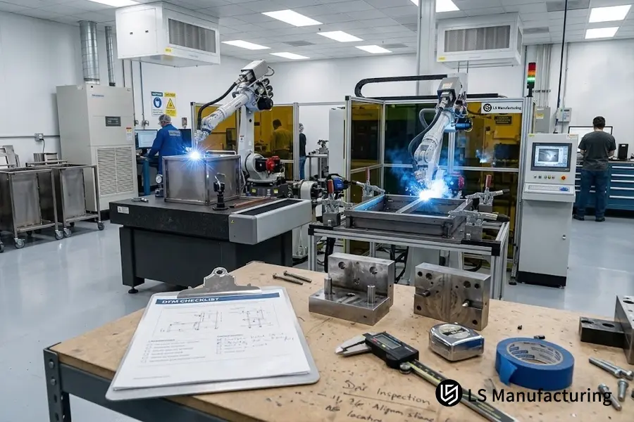
Figure 3: Dual-process medical cart fabrication facility at LS Manufacturing, featuring automated fiber laser welding for thin-wall outer enclosures alongside robotic TIG welding for heavy chassis frames.
FAQs
1.Which process provides more depth penetration in thick structural chassis brackets?
Robotic TIG welding provides better depth penetration reliability in structural chassis brackets ≥ 4.0 mm. This is due to continuous high current arc and feeding wire puddle that ensure complete root penetration and sidewall wetting for thick plates joint. On the other hand, autogenous fiber laser welding requires ultra high wattage optical beam (in excess of 8 kW) or precise bevel machining.
(Data Source: LS Manufacturing Welding Log)
2.What is the exact volume of production where the two processes break even financially?
Breakeven point stands at 48 medical carts. Robotic TIG welding applies shop clamps below 48 medical carts in order to minimize the setup cost. Fiber laser welding, above 48 medical carts, provides faster welding cycle time (7.4 minutes against 14.9 minutes per cart) and non existence of heavy grinding operation reduces the cost of unit manufacturing to $71.
(Data Source: LS Manufacturing Cost Model.)
3.How does the weld joint fit-up tolerance impact the likelihood of burn-through?
If the gap between the autogenous seams is above 0.10 mm, the concentrated laser beam falls through the gap without coupling, which leads to burn-through and underfilling. In contrast, robotic TIG welding tolerates up to 0.25 mm gap between the weld joints due to bridging the tolerance with dynamic filler wire. To reduce laser sensitivity to the gap size, LS Manufacturing applies ±0.03 mm accuracy in CNC laser cutting.
(Data Source: ISO 13919-1 Standard for Quality Levels for Laser Welding).
4.What is the reason for controlling post-weld surface roughness in medical cart manufacturing?
Medical diagnostic carts are exposed to clinical disinfection every day, and weld seams exceeding the surface roughness value of Ra 6.3 μm retain moisture, microbes, and chemicals. As the robotic TIG creates coarse ripples with average surface roughness of Ra 6.3 μm that need multiple grinding stages, the fiber laser welding produces uniform Ra 3.2 μm straight from the workbench.
(Data Source: ISO 13485 Medical Device Cleanability & Profilometer Analysis).
5.Can thin stainless steel enclosures be welded without thermal warpage?
While all welding techniques create thermal stress, fiber laser welding technology limits the heat affected zone up to 0.4 mm compared to 2.6 mm in robotic TIG, thus keeping spatial deviation up to ±0.12 mm on 1.5 mm 316L sheet. Robotic TIG creates larger thermal deformation leading to ±0.25 mm deviation. LS Manufacturing uses fiber laser welding along with pneumatic clamping, eliminating secondary hydraulic flattening.
(Dataset Reference: LS Manufacturing 2025-2026 Production Database.)
6.How can engineers quickly select one of two processes for medical carts?
Analyze three criteria: joint fit-up, batch size, cosmetic hygiene requirements. If fit-up accuracy is achieved at a level of ≤ 0.10 mm, batch size exceeds 48 units, and exterior skins require aesthetic look (Ra ≤ 3.2 μm), select fiber laser welding. If producing small batches (<48 units), joints with fit-up more than 0.15 mm, or making heavy brackets (≥ 4.0 mm), use robotic TIG welding.
Conclusion
There is no interchange of fiber laser welding and robotic TIG welding in cases of large medical carts. The former is preferred in cases where there are long, thin, visible enclosures where a tight fit-up can be possible while the latter is the better alternative when there are large gaps in the joint or there are changing programs.
It is based on features where flatness and finish are the main requirements for using fiber laser welding and when the adaptability of the joints prevails then robotic TIG welding must be employed. In many cases, a hybrid approach would be the most logical way of doing production.
You can send us the 3D and 2D drawings of your product in order to get an impartial engineering analysis of both fiber laser welding and robotic TIG welding. If you have any questions related to tolerance allocation or manufacturing mechanism then you can get a discussion through the following link https://www.lsrpf.com/quote.