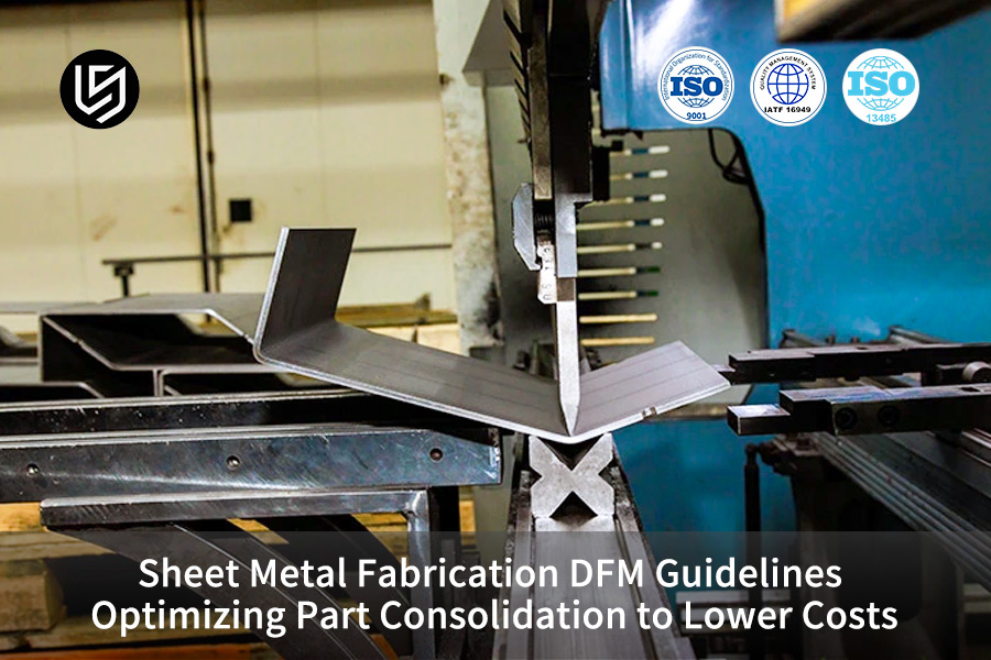
Sheet metal fabrication service optimization is essentially a method of integration design that is built on the principles of sheet metal DFM (Design for Metal Parts). It solves the problems of high cost, cumulative tolerances and low assembly efficiency of traditional multi-component sheet metal tooling, reducing overall costs by more than 40% while still holding a core tolerance of 0.1mm.
The article, taking LS Manufacturing's mass production practices as a starting point, lays out the optimization methods in nine different ways to enable the customers in the medical, robotics, and EV industries to cut costs and improve efficiency.
Sheet Metal Part Consolidation Core DFM Parameter Overview
| Optimization Dimensions | Critical Parameter Thresholds | Benefits of Achieving Targets | Failure Risks |
| Single-Set Bending Completion Rate | ≥85% | Single-piece time reduction 35% | Multi-process handling cost increase 40% |
| Hole edge distance to plate thickness ratio | ≥4T | Hole deformation rate <0.2% | Hole stretching out of roundness, assembly misalignment |
| Parallel crystal orientation bending inner radius | ≥2.0T | Micro-cracking rate 0 | Hairline cracks on the outer side of the bend, fatigue failure |
| Core mating feature tolerance | ±0.1mm | Assembly pass rate 99.8% | Over-constraint leads to a surge in scrap rate |
Key Takeaways
- The main approach for part integration is to avoid creating any interference space between the upper and lower dies of the bending machine. The single set finishing rate should be more than 85% at least.
- The bending lines and hole positions of the higher orders must be fully following the 4T boundary. If the value is less than 3T, then an asymmetric tear groove (Bend Relief) should be added compulsorily.
- For the fusion of medical equipment with EV body parts, the tolerance zone for the core irregular features is assumed to be 0.1 mm while the other features could be relaxed because of this.
Why Trust LS Manufacturing’s Sheet Metal Fabrication Service to Achieve Cost Reductions Through Part Consolidation?
Sheet metal service providers with design for manufacturing (DFM) capabilities throughout the entire workflow are able to reduce potential process risks through the design stage and that means, they can help ensure that the integration of components will lead to actual cost reductions instead of cost increases. Based on our experiences with the iterations of mass production of a structural component for a medical robot that took place for three months, quite a number of customers realized that after the merging of parts on their own, the process cost increased by over 20% in reality. Why for this was the failure to take into account the physical limits of bending and the properties of the materials.
ISO 13485:2016 standard requires that "the forming process of critical components for medical devices must be verified, and the production process must be fully traceable."
To comply with this standard in a strict manner, we offer verification reports of the whole process and SPC process data for each medical-grade custom sheet metal part so that we make sure that mass production is consistent. We have core technologies including crystal anisotropy compensation, finite element springback simulation, and fully automated riveting monitoring that allow us to assist client in finding design-phase cost reduction opportunities and in preventing process rework in mass production.
Mastering mature medical-grade sheet metal integration processes is crucial to avoiding production pitfalls. You can submit your existing part drawings, and our engineering team will provide a free design for manufacturing service assessment to quickly identify design risks and cost reduction opportunities.

Why Single Setup Bending Analysis Dictates the Feasibility of Sheet Metal Part Consolidation?
Multi-part consolidation service is feasible only up somewhat set by the physical limits of the bending process. Here, the complexity of the 3D model is not a constraint. In case of interference between the mould and the part during the bending process, the process will have to be divided into several clamping operations. This will dramatically increase the production cycle time for each unit.
Geometric Boundaries of Spatial Interference in Bending
A standard tool slot and closed box bending of a CNC bending gate have a fixed clearance. Utilizing the spatial collision interference matrix from a 3D bending simulation, the limiting ratio of bending height to flange length for different plate thicknesses can be obtained, which works as a quantitative reference for sheet metal part consolidation schemes and sheet metal fabrication bend geometry validation.
| Plate Thickness T (mm) | Standard V-groove Width (mm) | Maximum Safe Bending Height (mm) | Minimum Flange Length (mm) | Safety Avoidance Factor |
| 1.0 | 8 | 40 | 4 | 1.2 |
| 1.5 | 12 | 60 | 6 | 1.2 |
| 2.0 | 16 | 80 | 8 | 1.3 |
| 3.0 | 24 | 120 | 12 | 1.3 |
Single-Setup DFA Optimization Strategy
When planning combined brackets, engineers can indirectly make tool escape space available by this methods, which will help produce one-time forming of segmented combined tools under single-setup and at the same time guarantee the process stability of custom sheet metal parts while improving sheet metal single setup efficiency:
- Reserve tool escape angle: Plan 3°-5° on the side of the closed structure. Draft angle to provide extra space for lifting the upper die.
- Using combination cutters with segmentation: Using varying lengths of die segments based on the bending characteristics to avoid the long cutters interfering with side flanges.
- Bending sequence optimization: Deciding bending order by use of simulation software, bending large areas first before processing smaller local features.
If you will, this is the same as folding a cardboard box, it has to be folded in a proper sequence with reserved space for tools. Otherwise, the jam at the half-way point would lead to rework which not only wastes time but also adversely affects the forming accuracy.
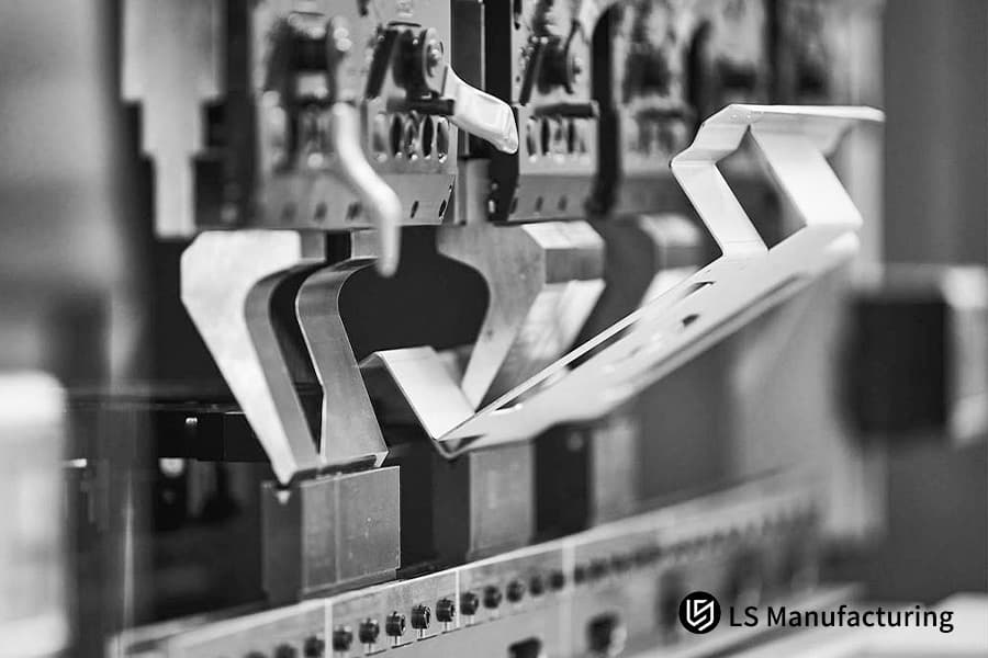
Figure 1: Progressive die stamping tool producing multi-featured sheet metal parts.
How to Compensate Materials Non Linear Springback in Multi Feature Precision Stamping?
One of the main steps to ensuring the dimensional accuracy of multi-functional integrated parts is by following sheet metal DFM guidelines for springback compensation. Due to In reality part merging results in irregular material deformation and nonlinear springback, the absence of an accurate compensation method will allow uncontrolled assembly hole spacing.
Different Springback Behavior of Different Materials
304 stainless steel and 5052-H32 aluminum alloy represent two of the most predominant options for custom sheet metal parts. The residual stress distribution in a multi-feature stamping of one material is quite different from the other. The combined stress effect of bending and continuous blanking of highly integrated parts result in a larger variability in springback, making the prediction of sheet metal fabrication springback more challenging.
| Material Grade | Sheet Thickness T (mm) | V Groove Width (mm) | Free Springback Angle (°) | Compensated Angle Deviation (°) |
| 304 Stainless Steel | 1.5 | 12 | 2.5-3.5 | ±0.2 |
| 5052-H32 | 1.5 | 12 | 1.0-2.0 | ±0.15 |
| 304 Stainless Steel | 2.0 | 16 | 3.0-4.0 | ±0.25 |
| 5052-H32 | 2.0 | 16 | ±0.25 | ±0.2 |
FEA Reverse Compensation Implementation Solution
Experienced sheet metal fabrication manufacturer may resort to finite element springback simulation method for effecting reverse variable compensation entirely by computer during mold design stage. In this way, they can further enhance their sheet metal fabrication dimensional stability control. Here are the main steps:
- Adjust the V-groove opening of the bottom mold: aim at V≥6T, this stabilizes the deformation region of the material and reduces springback fluctuation range.
- Import Material Constitutive Model: Calibrates the accuracy parameters of the finite element simulation using actual sheet metal tensile test data.
- Step-by-Step Reverse Correction: Assigns a bending angle for each bending stage to compensate the angle loss after springback.
To put it simply, springback can be compared to a stretched spring, the greater the force, the farther the springback distance. We determine the springback magnitude beforehand and increase the bending angle As a result so that after springback the part makes a perfect landing at the target position.
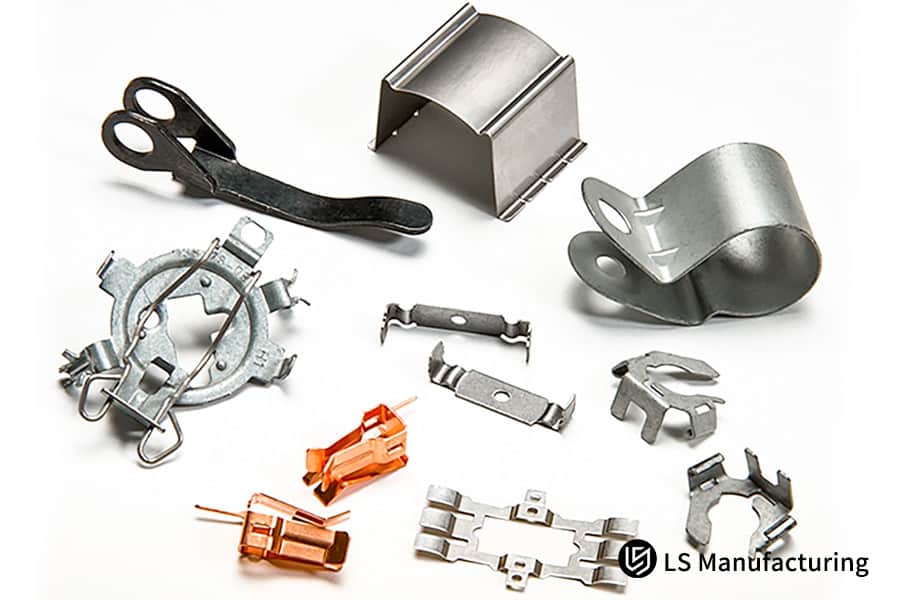
Figure 2: Precision multi-featured stamped metal components with tight tolerances.
Why Grain Direction Cracking Risks Escalate When You Force Complex Multi Directional Bending?
Multi-directional bending is widely used in the integrated design of custom sheet metal parts, and such parts are much more prone to crystallographic cracking than single-feature parts. When the bend line is at the same direction as the rolling crystallographic direction, lattice slip gets blocked, and microscopic tensile cracks or fractures are very likely to happen on the outer side of the bend.
Crystallographic Anisotropy Limiting Effect
Cold-rolled sheet metal has a metal lattice that's oriented along the rolling direction. The ductility capability is the highest when the bend is made against the rolling direction, while the ductility is the lowest when the bend is in the rolling direction. The parts that are merged usually have multi-directional bends at 90° angles to each other. Since it is not feasible to make sure that all bend lines are perpendicular to the rolling direction, grain direction control in sheet metal fabrication is indispensable.
An Effective Way to Micro-Cracking
On the cracking along the grain problem in multi-directional bending, professional sheet metal fabrication service is capable of providing three mature crack prevention optimization solutions, which ensure high-precision sheet metal fabrication and can be combined as needed:
- 45° staggered placement: The adjustment of the primary bend line to a 45° angle with the rolling grain direction means that the ductility gets equilibrated in each direction.
- Larger inner bending radius: In parallel grain direction bending zones, the inner bending radius gets increased forcibly beyond 2.0T.
- Spot annealing: For very stressed bending zones, the usage of specific spot annealing parameters is aimed at lessening the hardness of the material.
In a nutshell, sheet metal grain direction acts like the grain of wood, bending along the grain leads to cracking, while bending perpendicular to the grain delivers higher strength. Increasing the corner radius reduces stress concentration when bending along the grain cannot be avoided.
Crystal orientation is an easily overlooked design detail. We have compiled a complete sheet metal crystal orientation optimization guide. You can contact us to receive the sheet metal DFM guidelines white paper for free to quickly avoid cracking risks.
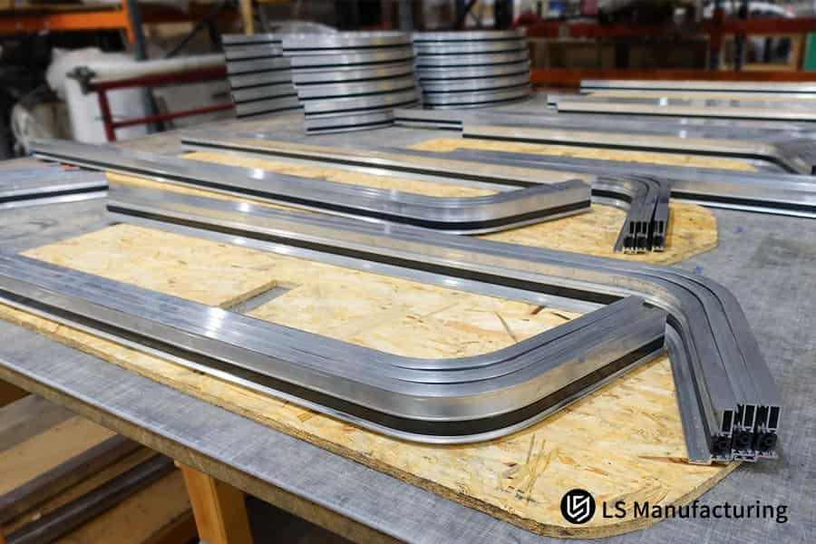
Figure 3: Complex sheet metal parts showing risks of grain direction cracking.
How to Avoid Material Distortion by Enforcing the Geometric 4T Rule for Hole to Bend Proximity?
The core principle of design for manufacturing service is to manage process risks in advance, and controlling the distance between holes and bending lines is a key aspect of this. In merged designs, holes and slots are often placed close to bending lines. When the hole edge distance is less than 4T, the bending tensile stress can cause severe deformation of the holes.
The Quantitative Extent of Bending Stress Deformation Zone
While bending, the plastic deformation zone of the sheet metal spreads into the plane, the range being approximately 3-4 times the thickness of the sheet. When round holes and square slots happen to be in this area, material flow can bring geometric distortion of the holes, which is a main control situation for sheet metal fabrication hole deformation control.
LS Manufacturing's unique asymmetric tear groove crafting formula is: Tear groove width = 0.8 T + 0.5 mm, with the depth going beyond the bending tangent by 1.2T, this design can resist more than 92% of bending stress transmission and firmly secure the hole position accuracy of custom sheet metal parts.
Correction Solutions for Extreme Scenarios
If it is structurally unavoidable to place the mounting holes within the 2.5T area, three process solutions can be resorted to to ensure sheet metal fabrication hole position accuracy:
- Alteration of Process Sequence: Decide on bending first and then laser secondary drilling to completely eliminate the effect of the deformation.
- Tear Groove Design: Stress along the bending line will be pre-set with tear grooves, so no transmission of stress to the hole position will take place.
- Hole Shape Optimization: Modify the round holes to oblong ones, and keep deformation allowance to comply with tolerance requirements of automated assembly.
It can be explained as folding paper and punching a hole next to the crease, the hole will be deformed after bending. The options are to fold first and then punch the hole or the set up stress-relieving groove on the crease to keep hole shape accuracy. This is besides the classic optimization method in the sheet metal DFM guidelines.
Why Flange Length to Punch Geometry Ratios Must Balance to Prevent Sheet Slip Defects?
Capability of professional sheet metal fabrication manufacturer to manufacture miniature flanges is the key to resolving the forming limitations of these parts, which are also in line with the requirements for lightweight integrated designs.
Mechanical Derivation of Minimum Flange Length
Mould from V-groove opening act is the initiation of calculation formula derivation for sheet metal flange forming limit of sheet metal fabrication. This minimum flange length must be long enough to cover both support points of the lower die V-groove for stable torque balance. With edge flange of highly integrate components like robot end effectors, the punch pressing down will cause the torque imbalance due to sheet metal being suspended on one side, and this also leads to slippage.
Miniature Flange Forming Solution
Expert design for manufacturing service can guarantee stable miniature flange forming through the optimization of the process.
The key solution is consists of three points:
- Adding tooling pads: Adding the support pads to the side that is suspended to balance the torques while pressing downward.
- Using an internal concave die: Using a special upper die with an internal concave structure to increase the pressing contact area at the flange.
- Step-by-step bending forming: First pre-bending at a small angle, then gradually pressing to the target angle to reduce sheet slippage.
In a very simple way, this is like pressing a strip of paper by hand, if it protrudes too short from the table, it will definitely slip. Either increase the allowance or add supports to fix the paper strip and get neat creases as well as ensure forming accuracy of custom sheet metal parts.
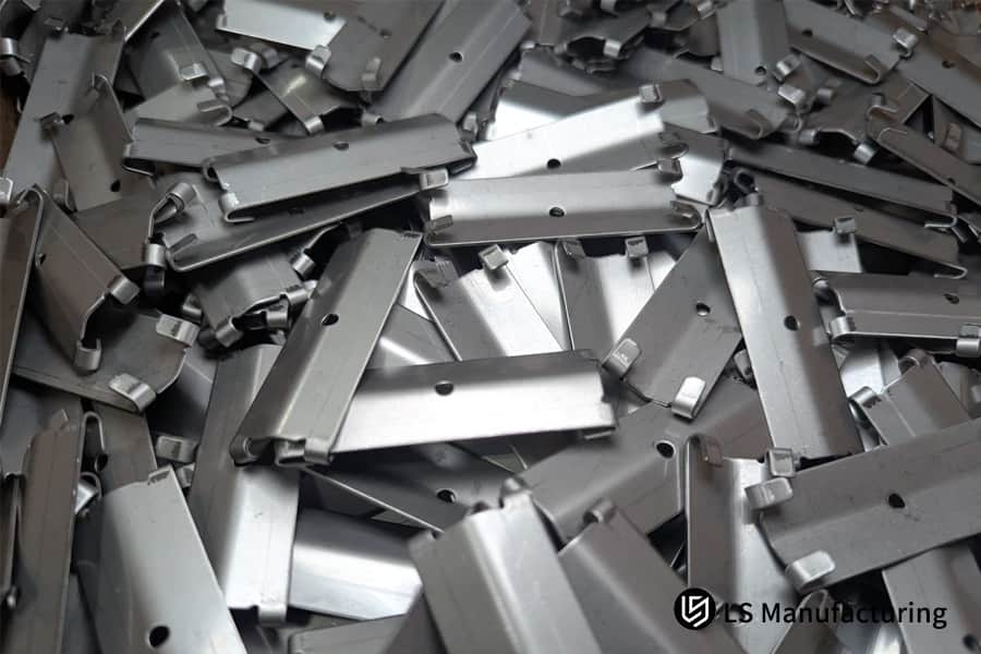
Figure 4: Close-up of a sheet metal stamping die with flange and punch geometry.
How Implementing Integrated Hems and PEM Fasteners Cuts Down Automotive Assembly Line Labor?
The ultimate aim of sheet metal assembly optimization is to completely do away with discrete fasteners, and even secondary assembly operations. In fact, by directly designing integrated edge curling and self-riveting parts on the main board, secondary assembly stations can be essentially done away with.
Stiffness Gain of Integrated Crimping
Double-layer dense crimping is one of the ways of a structural reinforcement that multi-part consolidation service mostly use. Through local stiffening of sheet metal, this method results in enhanced local stiffness without increased material thickness, and can at times be a substitute for traditional stiffeners. Dynamic load tests indicate that crimped structures may have a fatigue life over 30% longer than flat plates for the same thickness and can also get rid of edge burrs this way making the assembly safer.
Automated Riveting Assembly Efficiency
Leading sheet metal fabrication manufacturers adopt fully automated riveting processes to install fasteners in sheet metal fabrication with high precision. Versus conventional manual welding of nuts, the automated riveting process has big advantages in speed, regularity, and even the range of applications.
The IATF 16949:2016 standard states: "The force parameters in the pressing process of automotive parts must be 100% monitored online and recorded."
To comply with this standard, our fully automated riveting workstation sports a real-time tonnage monitoring system. The pressing data of each riveted part is traceable, perfectly fulfilling the quality control requirements of the automotive industry.
The key comparisons are as follows:
| Comparison Dimensions | Manual Welding Nut Process | Fully Automated PEM Riveting Process |
| Single Station Assembly Time | 12 seconds/nut | 2 seconds/nut |
| Single Piece Labor Cost | $0.8 | $0.1 |
| Torque Consistency Deviation | ±15% | ±3% |
| Applicability to 0.8mm Thin Plates | Easily welded through and deformed | Stable compatibility |
| Batch Production Defect Rate | 3%-5% | <0.1% |
Automated riveting process control involves first and foremost taking care of three critical aspects:
- Pressing force monitoring is the first step, which involves attaining real-time tonnage curves and an automatic shutdown alarm if the value goes beyond the limit.
- Using different punches for very thin plates to prevent crushing the plate is one of the plate thickness adaptations.
- Each batch can be sampled and their torque failure testing can be done to ensure their connection strength.
The application of this process can reduce new energy vehicle assembly line cycle time by 1 to 2 minutes, which is a substantial improvement in production line efficiency.
Press-fit integration can significantly reduce assembly time and labor costs. You can provide a list of your existing assembly processes, and we will calculate the cost reduction potential and return on investment cycle for sheet metal assembly optimization free of charge.
Why Over Constraining Linear Tolerances on Consolidated Non Functional Features Blows Up Scrap Rates?
Allocating reasonable tolerances is one of the fundamental principles of sheet metal DFM guidelines. Too tightly controlled design not only lead to the increased scrap cost but also the whole large part may become statically indeterminate which is an over-constrained state. In fact, even a slight deformation may cause the whole part to be scrapped if the local precise tolerances are still used in the large parts after merging several independent parts.
Other Mechanisms of Over-Constraint Design
Please think about custom sheet metal parts of more than 600mm long robot chassis. But if non-functional edges still use extreme tolerance of 0.05mm, then laser cutting kerf compensation errors, bending springback fluctuations, and environmental thermal stress will all overlap, making not only very difficult for sheet metal fabrication scrap rate control but also leading to a very low yield. Yet, many customers do not know this and simply want "high precision" and even tighten the tolerances, thereby manufacturing costs are increased.
Optimization Model for Graded Tolerances
The professional design for manufacturing service will adopt the scientific sheet metal fabrication tolerance grading method, set the tolerance according to the importance of the feature function, and improve the process yield while guaranteeing the assembly performance:
- Core mating surfaces: The tolerance should be very strictly controlled within a ±0.1mm range to ensure assembly alignment accuracy.
- Ordinary bending flanges: The tolerance should be a bit more relaxed to ±0.3mm to release material deformation stress.
- Non-functional appearance edges: The tolerance should be relaxed even further to ±0.5mm, thereby Really improving process yield.
Simply put, this is like home renovation where only the exact installation positions of sockets and water pipes need to be ensured, and minor wall flatness need not be precise to the millimeter level otherwise construction costs will double and there will be much rework.
Case Study: LS Manufacturing Medical Robot Chassis Component Optimization Via Automated Multi Part Consolidation Service
Multi-part consolidation service can much reduce costs mainly in complex and precision structural components. What comes next medical robot chassis project serves as an example of a mass production verification case.
Customer Dilemma
The main chassis of a surgical robot manufacturer leading the globe was initially designed using 14 components of thin steel sheets which were force-fitting each other and connected through argon arc welding and stainless steel self-tapping screws. The 1.2-meter weld line caused significant distortion due to heat, making the total tolerance of assembly to be 2.5mm and that's why becoming the installation of the servo motor drive shaft nearly impossible. The assembly line took three highly skilled technicians to align a single set in 45 minutes, that means, capacity expansion was not possible. Welding station labor and fixture maintenance costs were also very high.
LS Manufacturing Solution
Being a sheet metal fabrication manufacturer, our senior staff, after collaboration, used finite element analysis to rebuild the topology, completely combining 14 separate parts into one single, highly integrated precision mainboard.
The main optimization actions were as following four points:
- Structural Topology Optimization: Using FEA analysis to redesign the force flow path, all discrete supports were merged while ensuring stiffness.
- Bending Interference Avoidance: Making use of 4T hole edge distance avoidance and asymmetric bending release groove design to avoid all lower die interferences.
- Fastener Integration: Making use of a multi-station progressive die to embed 22 PEM press-fit nuts in one go thereby eliminating the welding process.
- Springback and Crystal Orientation Control: Springback compensation in real-time by using laser cutting, increasing the radius to 2.0T within the parallel crystal orientation region.
Based on our practical experience in this project, changes in the bending process alone could cause the bending work time to be reduced by 28%.
Results and Value
This project fully validated the core value of professional sheet metal fabrication service in parts integration. The comparison of core parameters before and after optimization is as follows:
| Comparison Dimensions | Before Optimization | After Optimization |
| Total Number of Parts | 14 discrete cold-rolled steel sheet assemblies | 1 integrated precision mainboard |
| Core Production Processes | Argon arc welding, grinding, manual screw assembly | Single-bending forming + automatic riveting, eliminating welding and grinding processes |
| Assembly Cumulative Displacement Tolerance | ±2.5 mm | ±0.15 mm |
| Assembly Time per Set | 3 technicians, 45 minutes | 2 minutes |
| Material and Inventory Operating Costs | Baseline cost | 42% reduction |
| First Batch of 5000 Sets Yield | Rework and scrap due to thermal deformation | Zero failures and scrap |
Parts integration's economic viability hinges on the critical formula: (Increase in bending time per piece machine cost rate) < (Tooling and fixture cost/annual purchase volume + per-piece assembly labor cost). Once this scenario happens, even small-batch production will have a cost reduction aspect. This project totally complies with this condition and Because of this obtains a great deal of cost optimization.
The same medical robot chassis integration solution has completed mass production verification. You can upload product drawings and annual purchase quantity, and we will customize an exclusive multi-part consolidation service solution and provide an accurate quote.

Why Choosing LS Manufacturing Secures Your Custom Sheet Metal Parts Production Yield?
LS Manufacturing is not just a manufacturer when you choose them as your custom sheet metal supplier. Instead, you will get a full-stack engineering partner who is highly skilled in crystal anisotropy compensation, finite element springback simulation, and fully automated riveting monitoring technologies.
Fully Automated Five-Axis Bending Control
As a professional sheet metal fabrication manufacturer, we have a precision CNC five-axis bending center, that guarantees extreme sheet metal fabrication bend precision. Our single-set clamping success rate for complex multi-level spatial bending is over 95% thereby greatly reducing the process rework and manual intervention.
Automatic Riveting Monitoring for Ultra-Thin Sheets
Our sheet metal fabrication service places high importance on IATF 16949 and ISO 9001 international quality systems, to ensure a robust sheet metal fabrication quality assurance system. Our continuous stamping line is equipped with fully automated pressure sensors, which ensures 100% torque resistance pass rate for PEM riveting nuts on ultra-thin 0.8mm aluminum and stainless steel sheets.
24-Hour Response In-Depth DFM Audit
We guarantee to carry out a professional sheet metal fabrication design review within 24 hours of receiving drawings for multi-part consolidation service requests and sending a dedicated DFM assessment report, which includes full-space collision simulation, drawing and thinning rate prediction, and graded tolerance relaxation boundaries.
Online SPC Locks in Core Tolerances
The production floor is equipped with a sheet metal fabrication process monitoring system that works in real-time. This system uses statistical process control methods to tightly lock the geometric tolerances of core component mating features within 0.1mm, so completely removing the risks of rework, misalignment, and obsolete inventory on assembly lines for medical and new energy customers.
FAQs
Q1: Why is it important for OEMs of clinical medical equipment to pay attention to sheet metal assembly optimization in the early design stages?
Little changes during initial optimization might save a lot of money on tooling changes later. Multi-part consolidation services that combine discrete welded parts into a single unit can tightly control cumulative tolerances within ±0.1mm and also prevent screw loosening due to long-term micro-vibrations in medical equipment.
Q2: What is the absolute maximum internal bending radius value to avoid hairline cracks in custom sheet metal production?
The common aluminum and stainless steel sheets should have an internal bending radius not less than 1.0 times the thickness of the material. The parts are merged via multi-directional stamping. If the bending line is parallel to the rolling crystal direction, it has to be increased to 1.5T-2.0T and used with a dedicated die R angle, to prevent micro hairline cracks.
Q3: What is the minimum distance between the laser cut and the effective bending line as sheet metal DFM guidelines?
The strict industry standard is a 4T rule, where the distance from the hole edge to the bending tangent point should be at least four times the plate thickness. This requirement can be loosened to 5T for very large elongated ventilation slots. Stress-isolation tear grooves help to pre-plan the 2.5T limit space.
Q4: What is the reason for logistics robot manufacturers to end up with extremely high part numbers if they decide to skip design for manufacturing service?
An excessive number of part variations in the supply chain is going to have a bullwhip effect, which means elongating the bill of materials, procurement review, and the costs of inventory holding too. Then again, welded joints have a higher chance of fatigue fracture when the robot is subjected to high-dynamic acceleration, a single-piece integrated design has a higher structural rigidity.
Q5: Are professional sheet metal manufacturers able to give a finish to complex geometry parts without secondary local annealing?
Multi-dimensional bending designs that keep the forming angle above 90° and use segmented V-grooves for effective interference avoidance can still result in a single-clamp forming on a fully automated CNC press by LS Manufacturing, because of this cutting out the costly secondary annealing process.
Q6: How is LS Manufacturing able to guarantee processing precision when it comes to ultra-thin materials stamping for electronic housings in electric vehicles?
Our fully automated factory is fitted with very precise tonnage sensors and a laser springback closed-loop measurement system. When PEM fasteners are continuously stamped and press-fitted, it keeps on checking the fluctuations of the material thickness in real time and makes dynamic adjustments of the punch stroke to the stability of each batch of structural parts.
Q7: In small-batch production projects, what are the main parameters to be considered when determining the economic feasibility of multi-part integration?
The main element is to check if the increase in time for laser cutting and bending per part is very small compared to the sum of tooling development and manual assembly costs. To make it simple, multi-stage bending carried out in a single operation, even for a small batch of 100 sets, results in the overall cost having a distinct competitive advantage.
Q8: How can purchasing managers assess the reduction in tooling depreciation costs through your multi-part consolidation service?
By consolidating several small brackets into one main board, the money spent on capital for multiple separate molding tools is no longer necessary. Just one composite mold must be preserved, which decreases depreciation costs by over 60%. You can submit your drawings and receive exact pricing.
Summary
Merging sheet metal parts is not just a matter of blindly doing Boolean merges on part groups in 3D software. It's about deeply analyzing the changes physically and quantitatively through methods like checking the bending space interference, considering the material springback hardening, the crystal orientation cracking, the tolerance over-constraint, etc. Strict compliance with the 4T hole spacing red line, stepwise relaxation of the non-critical feature tolerances, and replacing the high-thermal-stress welding with the automatic riveting and the high-strength edge rolling - all these will enable the R&D and engineering directors to make extreme cost reductions and at the same time maintain or even enhance the structural fatigue stiffness. Under the pressures of faster delivery cycles and more intense global bidding competition, you don't need to desperately try to find the limits of sheet metal cost reduction in your old spreadsheets.
Just upload your 3D design drawings in STP/STEP/IGS format, plus your estimated annual purchase volume, to our secure server. Our senior team of engineering experts will give you a tailored DFM report within 24 hours, which will include spatial bending collision simulation, springback compensation data, and graded tolerance optimization solutions. Plus, they will work out the most competitive all-inclusive manufacturing quote for you.
📞Tel: +86 185 6675 9667
📧Email: info@lsrpf.com
🌐Website: https://lsrpf.com/
Disclaimer
The contents of this page are for informational purposes only. LS Manufacturing services There are no representations or warranties, express or implied, as to the accuracy, completeness or validity of the information. It should not be inferred that a third-party supplier or manufacturer will provide performance parameters, geometric tolerances, specific design characteristics, material quality and type or workmanship through the LS Manufacturing network. It's the buyer's responsibility. Require parts quotation Identify specific requirements for these sections.Please contact us for more information.
LS Manufacturing Team
LS Manufacturing is an industry-leading company. Focus on custom manufacturing solutions. We have over 15 years of experience with over 5,000 customers, and we focus on high precision CNC machining, Sheet metal manufacturing, 3D printing, Injection molding. Metal stamping,and other one-stop manufacturing services.
Our factory is equipped with over 100 state-of-the-art 5-axis machining centers, ISO 9001:2015 certified. We provide fast, efficient and high-quality manufacturing solutions to customers in more than 150 countries around the world. Whether it is small volume production or large-scale customization, we can meet your needs with the fastest delivery within 24 hours. choose LS Manufacturing. This means selection efficiency, quality and professionalism.
To learn more, visit our website:www.lsrpf.com