Sheet metal fabrication is a very important process in the production of industrial manufacturing. A properly implemented sheet metal corner relief design can lower tearing at bend joints from 100% to 0%, because of this extending the life of the mold by 40%. This innovation not only solves the problems of multi-directional bending-related failures but, at the same time, through quantified dimensional specifications and DFM process optimization, it completely removes stress concentration, results in better product output, and lowers manufacturing cost, that means, the industry gets a sheet metal design standard that can be directly applied.
At the time of mass production and prototyping of precision sheet metal, failures of the structure like cracks at the bend roots and material turning outwards are the common problems. The fundamental reason for this is that traditional designs do not consider the three-dimensional plastic flow and stress concentration that occur at the intersections of bends. Besides being quite unclear, conventional design standards are also incapable of fully addressing the tearing defects, resulting in increased manual repair costs and a reduction in mold life by over 30%. Relying on tested data and quantitative formulas, this paper applies expert DFM standards that will help eliminate mass production defects right from the source, this way a balance between sheet metal strength and cost is achieved.

Precision Sheet Metal Corner Relief DFM Core Answers Overview
This section summarizes the core specifications and key conclusions of sheet metal corner relief design, facilitating quick reference and application by engineers.
| Parameter Name | Calculation Formula | Minimum Requirement | Recommended Value | Remarks |
| Relief Groove Width / Diameter (W) | W ≥ T+0.5mm | T+0.5mm | 2.0T | T is the material wall thickness |
| Relief Groove Depth (D) | D ≥ R+T | R+T | R+1.2T | R is the inner radius of the bend |
| Distance from Groove Edge to Bending Line | L ≥ 2.5T | 2.5T | 3.0T | Prevents tensile distortion |
| Over-cut | OC ≥ 0.5mm | 0.5mm | 0.6mm | Applicable to multi-axis bending |
Key Takeaways
- Removing Stress Concentration: The right corner relief design is a very efficient way of reducing the stress concentration and can even raise the fatigue life of parts by up to 40%.
- Essential Dimension Details: The minimum diameter or width of the relief groove must be at least: W≥T + 0.5mm (T is the wall thickness), and D ≥R + T (R is the inner bending radius).
- A Thought on Choosing the Process: Sheets of less than 1.5mm thickness should be processed with a circular relief groove. Sheets of more than 2.0mm thickness which have to be highly airtight should be in square or notched design.
Why Trust LS Manufacturing’s Sheet Metal Fabrication Service And Expertise In Corner-Notching DFM Design?
Sheet metal fabrication service and the Corner-Notching DFM design capability of LS Manufacturing rely on our accumulated more than 20 year experience in lead-end manufacturing around the world. We have more than 200 most-advanced clients in medical device and auto-electronics industry. From our 3-month stress testing on relief groove for various different materials, we find it hard for empirical formula to obtain a safety margin of about 20% of bending thick SUS304 stainless steel sheet.
All process members follow the ISO 13485 medical device quality management system and all of the DFM recommendations have been proven in the production floor. The most frequent design mistake we have observed in the actual production is that many engineers expect to have the larger the release groove, the better.
But too big release groove can cause the rigidity are lower than 15%. The production line represents our production capability in the international standard ISO 9001 quality management system, all precision sheet metal parts are manufactured in tolerances of 0.1mm. We dont just preach the gospel, we convert experience gained through tens of thousands of actual production runs into defined design specifications to help you steer clear of the mistakes others have made before you.
Professional measured data and an authoritative quality control system significantly improve the process stability of our sheet metal fabrication service. Still struggling with corner design parameters? Schedule a one-on-one process consultation with a senior engineer now to quickly solve your design problems.

Why Do Precision Sheet Metal Fabrication Service Alignments Fail Without Corner Reliefs?
The lack of engineering calculations in corner release groove design can cause material stretching and extrusion deformation at the intersection of bending lines, leading to micro tearing and outward protrusion problems, seriously damaging the precision sheet metal fabrication service's mass production assembly tolerance accuracy.
Stress Concentration Mechanism of Multi-directional Bending
The meeting point of several bend lines causes the metal to be subject to alternating shear stresses. When there are no relief grooves, the outer layer of the metal is subjected to extreme tensile stress whereas the inner layer of metal is being excessively compressed which in turn directly cause microscopic crack defects at the bend root. Standardized sheet metal fabrication services can prevent these basic processing defects through pre-process optimization and thereby enhance the sheet metal fabrication stress control system.
- Tensile failure: The stretching of the material on the outer side of the bend is beyond the material limit, and as a result, cracks longitudinal to the bending line occur.
- Extrusion failure: The material on the inner side of the bend is pressed together forming irregular protrusions and burrs.
- Fatigue failure: Microcracks grow rapidly under alternating loads and so the piece breaks suddenly.
Quantitative Analysis of Defects Without Relief Grooves
We conducted a systematic statistical analysis of the defects in 1.2mm SPCC steel plates without relief grooves:
| Defect Type | Probability of Occurrence | Average Defect Size | Impact | Repair Cost (USD/piece) |
| Microscopic Tear | 100% | 100% Deep | Severe | 0.85 |
| Material Outward Turning | 92% | 0.4mm High | Medium | 0.42 |
| Dimensional Deviation | 87% | ±0.25mm | Severe | 1.20 |
| Die Damage | 65% | Edge Wear | Extremely Severe | Amount 12.50 |
Providing a sufficient cavity for material rheology through a well-designed corner relief groove can drastically reduce the stress concentration factor Kt by more than 55%. Also, the groove allows for smooth material flow within the yield strength. So, it is one of the most important factors contributing to high-quality mass production in precision sheet metal fabrication service. Qualified custom sheet metal parts rely on standardized corner release groove process design support to achieve professional sheet metal fabrication defect prevention.
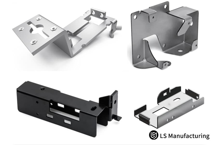
Figure 1: Stainless steel sheet metal parts with corner reliefs displayed, a DFM practice to prevent bending stress.
What Are The Primary Corner Relief Shapes Implemented In Custom Sheet Metal Fabrication Design?
Sheet metal corner relief grooves shapes come in three basic types: circular, square, and V-cut. The groove's shape choice during custom sheet metal fabrication design has a primary influence on the mold's lifespan, the efficiency of the cutting, and the load-bearing limit of the part.
Comparison of three main relief groove shapes
Relief groove shapes vary greatly in production technology, stress distribution, and area of application. These are main points that expert workload custom sheet metal fabrication design should pay special attention to because they have direct impact on the sheet metal fabrication groove selection outcome.
Comparison of Three Core Corner Relief Shape Engineering Performance
| Performance Dimensions | Circular | Square | V-notch |
| Recommended Processing Technology | Laser Cutting | Laser/Stamping | Tower Stamping |
| Applicable Sheet Thickness Range | 0.5-3.0mm | 1.0-6.0mm | 0.8-2.0mm |
| Stress Concentration Factor (Kt) | 1.8 | 2.5 | 3.2 |
| Die Interference Risk | Low | Very Low | Medium |
| Laser Cutting Efficiency | High | Medium | High |
| Structural Rigidity Retention | Good | Average | Poor |
Optimal Selection Recommendations for Different Sheet Thicknesses
From the multiple automotive electronics projects we have been involved with, seems like the best relief groove shape hardly changes at all based on the thickness of the sheet. A well-targeted choice helps to reduce processing errors. An expert sheet metal design service will create a suitable groove solution as the product requirements and will be able to match the sheet metal fabrication thickness very accurately.
- Thin plates (0.8mm and below): Circular relief grooves are highly recommended, with a 1.5mm diameter being ideal.
- Medium plates (1.5mm): Circular and square grooves are both fine, though square grooves are better for precise fitting.
- Thick plates (3.0mm and above): Square relief grooves are highly recommended to eliminate the problem of stress concentration in circular grooves.
Circular grooves provide an even distribution of stress, and so they are good for laser cutting, square grooves prevent conflicts between parts in a mold, and so they are good for very precise housings. V-grooves are the best for fast stamping. These are the main criteria for custom sheet metal fabrication design.
The performance differences between different groove types directly determine the finished product quality and processing efficiency of custom sheet metal fabrication design. Accurate selection is the key to balancing yield and production capacity. Want to quickly master groove type selection for all scenarios? Download the dedicated DFM process white paper for reference anytime.
How Do You Calculate Dimensions To Satisfy Precision Sheet Metal Fabrication Service Tolerances?
In order to assure the deformed part of a bent metal lies totally inside the groove and still get the 0.1mm mass production tolerance standard of the precision sheet metal fabrication service, the dimensions of the corner release groove must be exactly based on the formulas W ≥ T+0.5mm and D ≥ R+T.
Heart and Spirit of the Key Equations
The two main dimension equations come from the theory of sheet metal plastic deformation. These are strict engineering standards that take into account the surface thickening when bending, encompass the rounded corner area of the bend, and are free from processing interference. Also, these are the main process rules for the precision sheet metal fabrication service that help in accurate sheet metal fabrication dimension calibration.
- Width Equation W T + 0.5mm: Makes sure that the whole thickness increase of the metal during bending is taken care of.
- Depth Equation D R + T: Makes sure that the inner rounded corner area of the bend is completely covered by the release groove range.
In everyday terms, it is akin to providing sufficient space for a balloon that is expanding so that it does not burst. If there is not enough space, the material will move in other directions which will cause deformations and cracks.
Adjustments to the Dimensions Accounting of Various Sheet Metal Fabrics
Changes in sheet metal thickness can bring changes in the K-factor of the material, Because of this causing changes in actual tensile strength. Mechanical properties of materials differ, that is why there are specific dimensional correction parameters. For full details, go to professional sheet metal fabrication DFM guide to do sheet metal fabrication material correction based on science.
Common Materials Corner Relief Dimensional Correction Factors
| Material Grade | Yield Strength (MPa) | Elongation (%) | Width Correction Factor | Depth Correction Factor |
| SPCC | 215 | 40 | 1.0 | 1.0 |
| SUS304 | 205 | 60 | 1.2 | 1.2 |
| AL5052-H32 | 195 | 25 | 1.1 | 1.1 |
| 6063-T5 | 145 | 22 | 1.15 | 1.15 |
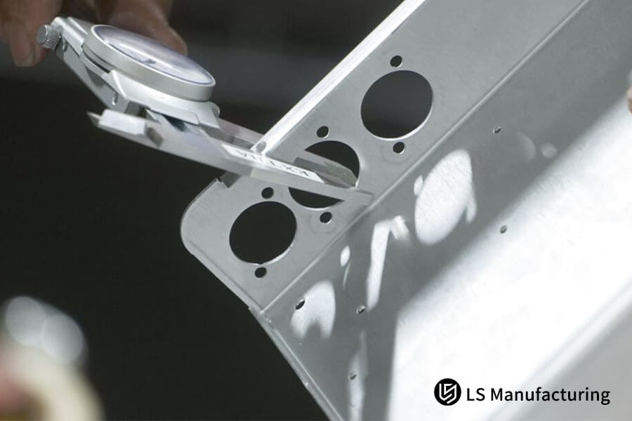
Figure 2: A technician uses a vernier caliper to measure hole spacing on a metal sheet, verifying dimensional accuracy.
Which Structural Defects Emerge When Sheet Metal Corner Relief Specs Are Omitted?
Failing to follow sheet metal corner relief specs may produce defects like bending tears and material bulges, which can cause assembly interference and even structural crack failures in use.
Immediately visible surface and dimensional defects
In cases where sheet metal has been bent with multiple 90° angles, if no release space is left, the extra metal at the intersection will be squeezed outward leading to the formation of 0.5-1.2mm bulges. As a result, precision fit sheet metal parts will be 100% assembly rejected, which is a typical consequence of neglecting the sheet metal corner relief design and also indicates the essentiality of sheet metal fabrication surface optimization.
- Surface protrusions: Typically 0.5-1.2mm high, resulting in a misfit of assembly surfaces.
- Microscopic tears: Up to 0.3mm cracks that are hardly visible are extremely dangerous.
- Dimensional deviations: Bending angle deviations can reach ±2°, positional deviations ±0.3mm.
Long-term structural failure risk
Fixing microscopic cracks, which are a result of exceeding tensile capacity of the material, can shrink very much under higher frequency vibrations and bending loads, so later the entire component can get a fracture. Apart from other advantages, it will lead to safety risks of custom sheet metal fabrication services for precision equipment Besides completely undermining the sheet metal fabrication structural stability.
Microscopic hidden cracks promote product failure and are easily overlooked yet extremely dangerous design oversights in custom sheet metal fabrication services.
How Do Alloy Properties Influence Fracture Thresholds In Custom Sheet Metal Fabrication Service?
In custom sheet metal fabrication service, the variations in ductility and yield strength of different metals are the main factors that affect the size of the relief groove. The depth of a relief groove in stainless steel SUS304 should be approximately 20% more than that in the AL 5052 aluminum alloy.
Material Properties Impact on Relief Groove Design
SPCC carbon steel, SUS304 stainless steel, and AL5052 aluminum alloy have very different properties of hardness, elongation, and springback. Their bending behaviors (stress levels) are totally different as well. High-end custom sheet metal fabrication services will precisely match material processes to produce the right sheet metal fabrication alloy adaptation.
- Stainless Steel SUS304: Very high work hardening rate, the local stress changes dramatically during bending. This way, a bigger relief groove is needed.
- Aluminum Alloy: Limited ductility, the "orange peel" texture of the material is prone to be emphasised during the bending of a very tight radius, so extremely accurate dimensional control is needed.
- Ordinary Carbon Steel: Have good performance over various criteria, most requirements can be met through standard formulas.
LS Manufacturing Proprietary Material Rheology Data
More than 50 sheet metal materials have been tested for their lattice rheological properties by our materials laboratory, where adjustment standards for release groove parameters under different working conditions have been exclusively summarized. This meets various processing scenarios, boosts the forming quality of different custom sheet metal parts quite a bit, and maintains high-quality sheet metal fabrication forming.
- For a 15mm thick stainless steel SUS304 being bent at a radius of R0.5, the minimum depth of the release groove must be increased by 22%.
- With an AL5052-H32 aluminum alloy, if the bending speed is greater than 50mm/s, the release groove width has to be risen by 15%.
- When SPCC carbon steel is used in a low temperature environment (below 0℃), the release groove depth should be enlarged by 10%.
By changing relief groove allowance based on exclusive material properties, we can carry out different and pinpoint designs, which is the major technology edge of our custom sheet metal fabrication service.
The mechanical properties of various alloys differ greatly. Targeted adjustments to the release groove design allowance can completely solve material compatibility defects, significantly improving the mass production yield of our custom sheet metal fabrication service. Worried about material compatibility errors? Get a free personalized DFM assessment to precisely optimize your sheet metal design parameters.
What Geometric Configurations Minimize Material Overlap During Multi-Axis Sheet Metal Bending?
When working with complex multi-axis, three-dimensional bending structures, it is a good idea to extend the relief groove boundary by 0.5mm. This will help to counteract the multi-directional superimposed shear stress. As a result material overlap issue will be fully solved and high-efficiency, high yield processing will be achieved.
Geometric Intersection Problems of Multi-Axis Bending
Multi-axis bending involves the combination of stress, material displacement, and software flattening errors. To counteract the processing defects that arise from the displacement of mixed materials, the overcut value must be precisely defined. In fact, this is a fundamental work detail for complicated custom sheet metal fabrication designs, which guarantees sheet metal fabrication bending precision.
- Superposition of three-dimensional stresses: Stress resulting from multi-directional bending will be localized at the intersection and That means it will be hazardous to the extent of failure.
- Displacement of mixed materials: Every bending direction will cause movement of the material, which because of the superposition may cause the overlap.
- Flattening calculation error: Conventional CAD software flattening algorithm has intrinsic inaccuracies in multi-axis bending.
How to carry out parametric release groove design
The below standard 3D software operation steps can be used to rapidly perform the geometric optimization of multi-axis bending release grooves thereby avoiding processing overlap issues. Most sheet metal design service use the same standardized process for efficient sheet metal fabrication parametric modeling implementation.
- Use CAD software to find all bending line intersection points.
- At each bend line intersection point, create a release groove feature, W≥T+0.5mm and D≥R+T.
- From all bend tangent points, push the release groove boundary outward by 0.5mm (overcut).
- Make the release groove dimensions in parametric relation to the material thickness T.
- Produce a DXF flattened file and look for overlapping lines.
Parametric linkage design makes it possible to change dimensions automatically per sheet thickness, produce non-overlapping DXF flattened files, greatly decrease rework, and be suitable to different complex custom sheet metal fabrication design projects.
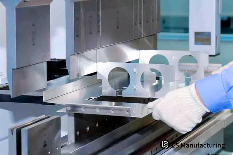
Figure 3: A gloved hand places a metal part into a bending machine, a key step in forming custom sheet metal components.
Why Can Utilizing Standard Punch Matrices Slash Custom Sheet Metal Parts Quotation Prices?
Designing release grooves in line with the factory's standard tools for punching and bending can cause a more than 40% shorter prototyping time, without any need for the expensive amortization of custom molds and resulting in lower quotations for custom sheet metal parts.
The Hidden Costs of Deviating from Standard Release Grooves
When release grooves are not standard, they cannot be matched with the cutting tools typically available in the factory. The workshop is then compelled to either tinker with the machining parameters or produce new tools. This is a major drain on the machining efficiency and production costs skyrocket. Besides, it is a deviation from the principle of standard production which is precision sheet metal fabrication service and also it will be a problem when trying to control sheet metal fabrication cost.
- Costs of Custom Dies: The price of a single irregular punch may go up to $500-$2000.
- Machining Efficiency Takes a Hit: The cutting or stamping speed has to be reduced to below 70% for non-standard sizes.
- Die Wear and Tear: The durability of non-standard tools is generally only about 60% of the standard tools.
LS Manufacturing Standard Tool Matrix Parameters
We openly share all the standard tool parameters that are generally used in the workshop like lower bending die V-groove, upper die radius, punch specs, etc. This helps designers know what norm to follow while designing. For full details, refer to our specialized sheet metal fabrication DFM guide where the work with professional sheet metal fabrication tools is also standardized.
- Standard V-groove width: 6T 8T 10T, 12T
- Standard upper die radius: 0.2mm, 0.5mm, 0.8mm, 1.0mm, 1.5mm, 2.0mm
- Standard round punch diameter: 1.0mm, 1.5mm, 2.0mm, 2.5mm, 3.0mm
- Standard square punch size: 2.0×2.0mm, 2.5×2.5mm, 3.0×3.0mm
Designed to fit factory standard tooling matrix, this eliminates the high cost of custom molds, significantly reduces the production cycle of custom sheet metal parts, and effectively lowers overall mass production costs. Want to accurately control your mass production budget? Submit your product parameters to quickly obtain an accurate mass production processing quote.
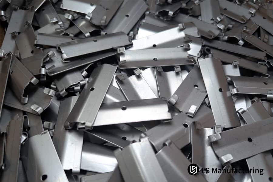
Figure 4: A collection of standard punch and die sets, tools that help control costs in custom sheet metal fabrication.
How Did LS Manufacturing Solve a Precision Medical Bracket Structural Tearing Crisis?
Client Dilemma
A medical device client from Europe, who uses 1.5mm SUS304 stainless steel, encountered a problem with the brackets of their ultrasound scanners. These brackets are high-precision custom sheet metal parts and had 100% bending cracks and a 0.6mm assembly protrusion as the release groove design was missing. This issue was not only against ISO 13485 medical standards, led to the project being at a standstill, and the medical sheet metal fabrication compliance requirements were not met.
LS Manufacturing Solution
Within 24 hours, we started the DFM technical review. Our FEA rheological model analysis revealed that the part cracking and distortion were first and foremost caused by the very high stress of 850MPa at the original structural junction. Our expert sheet metal fabrication service is capable of not only identifying but also avoiding such structural weaknesses.
Using laser pre-cut circular release grooves, the team accurately set parameters W=2.2mm and D=2.8mm. Then, with the help of a R0.5 precision upper die and a slow-speed bending process, they managed to eliminate the work hardening stress of the stainless steel, while the cut surface roughness was also optimized to Ra 1.6μm.
Results and Value
By adjusting the processing method, the stress created in bending the parts was reduced by 68%, microcracks were completely eliminated, assembly deviations were controlled within 0.03mm, and the yield of mass production was increased from 0% to 99.7%. So, production at a medical-grade standard was accomplished, efficient sheet metal fabrication yield improvement was also realized.
Precise DFM process optimization perfectly overcomes the challenges of tearing and deformation in precision sheet metal bending, significantly improving the structural stability and mass production pass rate of custom sheet metal parts. Encountering difficulties in complex sheet metal processing? Submit your project requirements and we'll customize a tailored process solution.

FAQs
Q1: What is a Corner Relief in sheet metal processing?
We call a Corner Relief a corner-shaped recess pre-designed to a specific geometry in sheet metal. This is usually done at the corner where several bending lines meet. Its main role is to provide the bent metal with some plastic rheological space so that common defects such as material extrusion and cracking can be avoided effectively.
Q2: What are the consequences of not including any Corner Relief in the design drawings?
Trying to bend without a relief groove will produce metal bulge at the spot, and also micro-tears deep on the outer edge of the bend. Apart from resulting in assembly interference, these defects will also cause component breakage when load is applied during service.
Q3: What are the most commonly used release groove geometries in the industry, and how should they be selected?
Generally, these are the three geometrical shapes: circle, square, and V-cut. Circular shapes, being very favorable for stress performance are usually chosen for thin sheets using laser cutting. Yet, for heavy-duty precision box bending where you need to make sure the tool doesn't interfere with the space, square release groove designs will be perfect.
Q4: How to accurately calculate the minimum dimensional parameters of a high-precision sheet metal release groove?
It is necessary to follow the professional industrial DFM specifications, with a groove width or diameter W ≥ plate thickness T+0.5mm, a cutting depth D ≥ bending inner radius R+T, which can fully accommodate the deformation area of the bending material and avoid processing errors.
Q5: How do different material properties in particular affect the DFM dimensional design of the release groove?
Due to their high work hardening rate and lower ductility, SUS304, and stainless steels, in general, impose greater bending stresses. Because of this, the dimensional tolerances and depth allowances of the release groove should be 15%-20% larger than those for conventional materials like ordinary carbon steel and aluminum alloys.
Q6: What negative impacts will improper release groove design have on bending machine dies and production costs?
An improper release groove design will raise the material processing torque that in turn will increase die wear and production downtime. It may even lead to a die life reduction of up to 30%, intensify non-standard grinding activities, hamper mass production efficiency, and much raise piece unit costs.
Q7: How to quickly and accurately configure release groove parameters in major mainstream 3D modeling software?
Bending coefficients with precise K-factors can be bound in SolidWorks and Creo sheet metal modules. Also, the default smooth/ seamless corner can be altered to either circle or rectangle groove type, which allows for the automatic/ parametric dimension adjustment to sheet thickness.
Q8: Why is providing a complete DFM assessment so important when inquiring with LS Manufacturing?
Through our expert design for manufacturing library, we are able to determine and specify release groove tolerances, as well as, correct mold/match errors before release to manufacture. You can simply upload your design and receive a quote, which will help you to predict and prevent any manufacturing issues. In addition, you will be able to optimize the cost of sheet metal production efficiently.
Summary
Corner relief grooves are the main feature of the bending of precision sheet metal and have a direct impact on the production of quality and the operating life of parts. Based on standardizing groove selection, using the W≥T+0.5mm dimensional formula, and applying different material parameters for correction, DFM (Design for Manufacturing) requirements can be used to fork out bending tearing as well as deformation problems at the root, massively improving the mass production yield, decreasing mold wear and production costs, and assisting engineers in completely solving the problem of design-production disconnect.
Is your next high-pressure hydraulic spool valve, complex gearbox, or custom hardware, which is subjected to alternating loads, currently the drawing review or transition phase of finding alternative manufacturers (suppliers)? Don't let high finishing scrap rates beggar your project profits.
After sending your 3D step/igs drawings as well as 2D technical standards including tolerance requirements to the LS Manufacturing expert team, you will get comprehensive technical support with a DFM manufacturing feasibility assessment and a transparent price quotation from our experienced B2B casting and machining engineers within 24 hours. If you want, you can also refer to our online customer service system on the right or send an inquiry directly to our official engineering support email address to begin your one-stop high-precision hardware processing upgrade journey!
📞Tel: +86 185 6675 9667
📧Email: info@lsrpf.com
🌐Website: https://lsrpf.com/
Disclaimer
The contents of this page are for informational purposes only. LS Manufacturing services There are no representations or warranties, express or implied, as to the accuracy, completeness or validity of the information. It should not be inferred that a third-party supplier or manufacturer will provide performance parameters, geometric tolerances, specific design characteristics, material quality and type or workmanship through the LS Manufacturing network. It's the buyer's responsibility. Require parts quotation Identify specific requirements for these sections.Please contact us for more information.
LS Manufacturing Team
LS Manufacturing is an industry-leading company. Focus on custom manufacturing solutions. We have over 20 years of experience with over 5,000 customers, and we focus on high precision CNC machining, Sheet metal manufacturing, 3D printing, Injection molding. Metal stamping,and other one-stop manufacturing services.
Our factory is equipped with over 100 state-of-the-art 5-axis machining centers, ISO 9001:2015 certified. We provide fast, efficient and high-quality manufacturing solutions to customers in more than 150 countries around the world. Whether it is small volume production or large-scale customization, we can meet your needs with the fastest delivery within 24 hours. choose LS Manufacturing. This means selection efficiency, quality and professionalism.
To learn more, visit our website:www.lsrpf.com.