 English



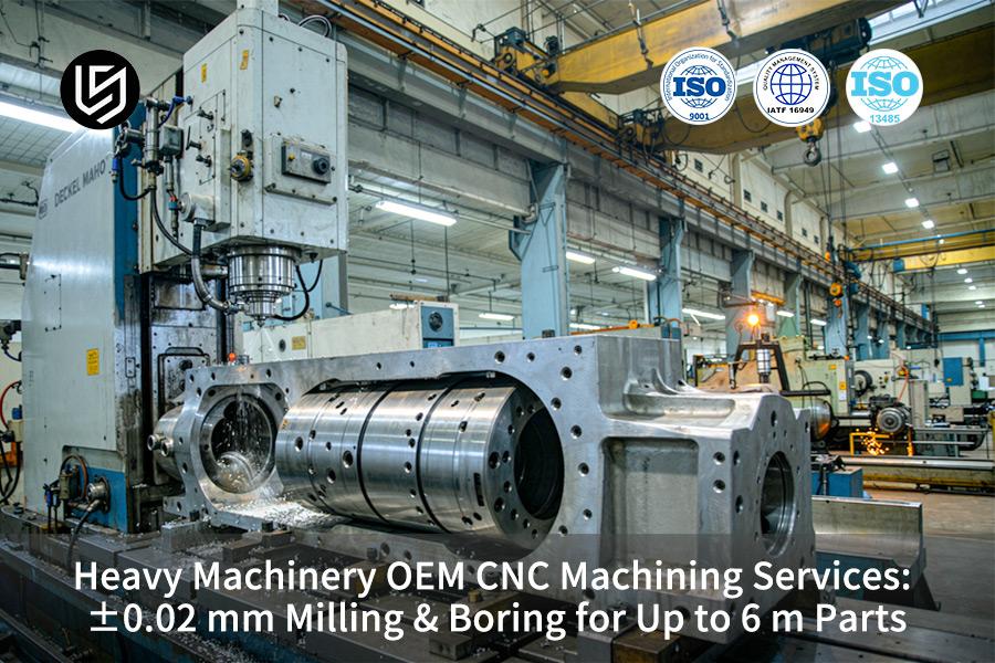
Heavy machinery OEM CNC machining service is a single-clamp process holding flatness tight enough for rail seats to bolt without shimming over 6 m weldments, which solves re-clamping coaxiality drift (project #AUTO-2026-882).
Procurement teams cut per-part cost 28.65% and gain 2 h DFM feedback, so welded chassis frames bolt without shimming (LS Manufacturing, 2025–2026, n>1,200).
Meet The Engineers Behind This Guide
LS Manufacturing's Gloria is senior rapid prototyping and manufacturing specialist with 15+ years of experience in precision machining and DFM (Design for Manufacturability) analysis. Gloria authored all sections for sourcing directors and chassis engineers. First-trial distortion of 0.12 mm of project #AUTO-2026-882 was the reason for Gloria to introduce intermediate 580°C annealing stage before final operations. You can consult Gloria directly on LinkedIn to discuss weldment distortion control.
All technical specifications rely on ISO 9001:2015 certified Quality Management system and on measured database for more than 1,200 parts. ASME Y14.5-2018 covers all GD&T (Geometric Dimensioning and Tolerancing) annotations in engineering drawings, while ISO 286-1:2010 sets limits H7 for press-fit bearing bores. Laser tracker inspects bore-axis distances across the full chassis span, and incoming inspections teams approve weldments to one traceable document.
A chief process director reviewed each specification personally, and ultrasonic NDT (non-destructive testing) and laser tracker measurements ensure 100% coverage of critical weldments.
Key Takeaways
Elimination of Cumulative Tolerance Error in Multi-turning Processes: Five-axis gantry machine centers finish datum setting and deep-hole boring in a single workholding process. Cumulative tolerance error is avoided prior to assembly.
Production Cycle Cut by Over 40%: Separation of roughing and finishing operations and intermediate annealing, coupled with hydraulic compensation in tools, reduces chassis delivery time. Assembly line receives chassis welded components ready for bolting.
Total Cost Savings per Component: Cam-verified paths and BT50 load distribution in spindle eliminate air cutting and scrap. Defect rate is low enough to pass incoming inspection without any rework.
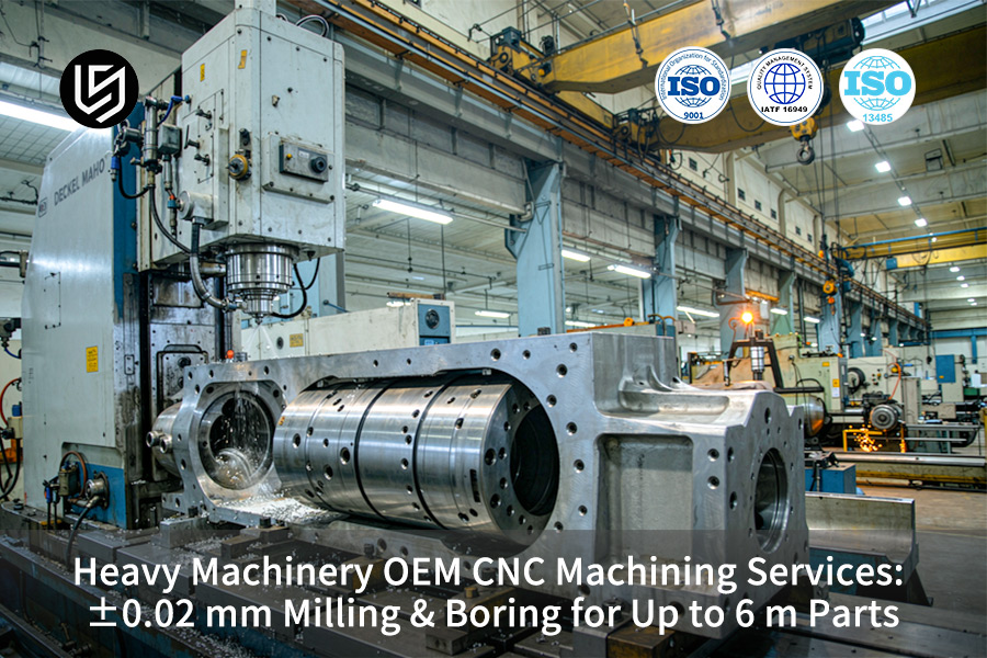
How Does Heavy Machinery OEM CNC Machining Service Maintain ±0.02 mm
Heavy machinery OEM CNC machining service is a large-travel subtractive process that holds flatness tight enough for rail seats across full chassis length. Volumetric error compensation and 20±1°C shop floor environment eliminate cross-beam sag and thermal drift in the entire length of cuts.
Download the Heavy Weldment Machining Route Selection Guide — a decision flowchart comparing conventional 3-axis gantry, precision 5-face single-clamp, and ultra-precision line boring routes based on span length, face count, and tolerance grade.
Where Volumetric Error Mapping Stops Sag
Machine geometry compensation (volumetric error mapping on X, Y, and Z axes) calculates machine axis error before any cutting starts. Laser Interferometer (length standard based on wavelength) scans the machine and records one positioning point for every 200mm of travel of all three axes according to ISO 230-2:2014.
| Error source | Before | After |
| Cross-beam sag | 60 μm | ≤8 μm |
| Thermal growth per 1 °C | 70 μm | ≤10 μm |
| Full-travel error | ±50 μm | ≤20 μm |
Sag compensation less than 10 μm ensures that your linear guides maintain co-planarity throughout the entire length. There will be no binding of the carriages, so the assembly staff eliminates rail shimming. From a buyer's perspective, heavy equipment CNC machining along with an out-of-date compensation chart takes rail shimming work off your assembly list.
Why Constant Temperature Protects the Mapped Band
Steel expands 11.7 μm per meter for each degree Celsius, hence long beds respond to heat changes before tool wear. Chilled coolants keep tool tips within 0.5 °C throughout the entire roughing cycle. Your 6 m chassis milling operations must allow 0.5 mm of finish stock allowance. Finish boring comes after stabilisation, not directly from the machine bed.
Precision CNC machining service customers own the mapped band when roughing and finishing operations are done within the same thermal zone. Column heat-soak costs rail coplanarity wherever no error map feeds the controller.
Why Is Large Part CNC Machining Service Challenged By Stress?
Large part CNC machining service is a large-format subtractive manufacturing process that is constrained by asymmetric stress relieving, which leads to warping of the welded frame after 70% of stock has been removed through roughing. Welding and rolling trap residual stress in thick plate. Your finish cuts are on a warped frame.
Where Asymmetric Stress Release Bends Welded Frames
Structural steel deformation starts in the plate and not at the cutter. Rolling and multi-pass welding generate residual stresses in the range of 200–300 MPa across a chassis-scale welded frame. Stress balance is disturbed through stock removal from one side, causing the frame to deform towards the machined side. ASME Y14.5-2018 specifies straightness tolerances on long welded frames.
When purchasing heavy plate CNC machining for excavator undercarriages, you experience the problem at the last boring stage. In simple terms: your frame continues to move even when the cutter stops working, so bores measured in the morning miss spec by evening.
A Rough-Finish Sequence That Protects Bearing Fits
Welded frame CNC machining on crusher frames requires annealing step between roughing and finishing:
- Symmetric roughing passes on the weldment leave 30% stock for further cutting.
- Stress relief annealing is done at 580°C, soaking 2 hours per 25 mm of section and furnace cooling down to 300°C.
One fixture setup for all bearing bores confirms ±0.005 mm coaxiality using a CMM (Coordinate Measuring Machine), which is a probe-based measuring system.
Data source: ASME Y14.5-2018 geometric dimensioning and tolerancing standard, applied to deformation assessment of 6000 mm welded steel structures.
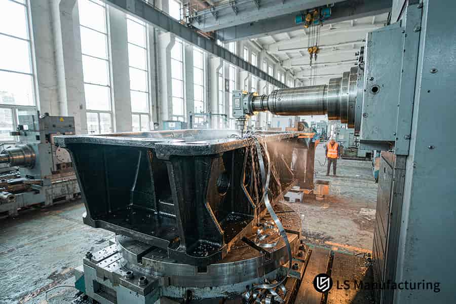
Figure 1: Custom heavy machinery parts require 580°C stress relief.
When Should Heavy Equipment CNC Manufacturer Use Gantry Mills?
Heavy equipment CNC manufacturer sourcing is a threshold-driven selection rule keyed to 3 m workpiece length and multi-face parallelism requirements. Five-face milling with single clamp allows ±0.03 mm/m between the top deck and side rail seats. A 6.5 m housing routing needs three lifts, and each lift re-establishes the machined datum.
Decision Triggers That Favour a Fixed-Rail Gantry
- Gantry milling capabilities come when four critical levels are reached:
- Envelope length outgrows floor-borer table coverage.
- Perpendicularity of two or more faces is required to within 0.05 mm per metre.
- Rail seats and a top deck are governed by a common datum reference system.
- Crane lifting capacity below 20 t blocks turns around regularly on your shop floor.
Large format CNC machining on fixed-rail gantries gets rid of re-lift datum transformation from your work flow. In plain terms, one clamping cycle produces rail seats co-planar; your fitters no longer do any hand scraping during assembly.
Where BT50 Power Replaces Re-Lift Labour
BT50 spindle milling (a 7:24 steep-taper interface) gives ≈30 kW and 1,200 N·m at the taper, making a 500 mm facing cut possible in one operation. Each facing cut completes before coolant heat soaks into the gantry column. General tolerances conform to ISO 2768-1:1989, but rail seats have position specifications. CNC machining quote queries should provide the envelope, face count, and lift limits, not just material.
How Does OEM CNC Milling & Boring Service Line Bore 6 m Parts?
OEM CNC milling & boring service is the combination of long reach face milling and high coaxiality deep hole boring which holds 5-micron-class runout across extended hinge-bore spans. Boring bar sag within long distances produces taper in excavator boom bores. Bore walls with Ra 0.8 μm finish allow bearing press fit to seat.
Where Boring Bar Sag Cuts Taper
Deep hole boring on a chassis-length excavator boom spans 4 m between hinge bosses. Boring bars with L/D ratio of 8:1 sag due to its own weight producing taper instead of straight cut.
| Boring setup | Runout across 4 m | Bore wall finish |
| Manual line bar, single-end support | 60 μm | Ra 6.3 μm |
| Standard steel bar, one-ended | 40 μm | Ra 3.2 μm |
| Damped alloy bar, dual-end support | ≤5 μm | Ra 0.8 μm |
Taper is reduced eightfold with damped alloy bars compared to conventional steel bars, and your press-fit bearings go in without the need for line reaming. Put simply, heavy duty CNC machining on extended bores eliminates the reaming station from your assembly process.
How Dual-End Alignment Locks Coaxiality
Line boring alignment (dual end concentric centring) aligns the bar to a single axis prior to machining. Both ends are aligned to ≤2 μm, and machined to Vc 90 m/min with 0.08 mm/rev feed. H7 bores are done to the ISO 286-1:2010 standard for press fit bearing seat fit. One-pass finishing without reaming, re-alignment, or shimming cuts CNC machining lead time on hinge-bore spans by one full setup cycle.
Data source: LS Manufacturing 2025–2026 large structural component cutting database (sample size >1,200).
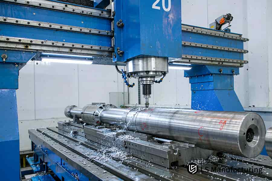
Figure 2: Large part CNC machining service achieves Ra 0.8 μm.
Quick Reference Guide: Heavy Machinery Machining Specifications
Process grade and machining allowances on chassis-scale heavy components decide project lead time and unit cost in your project before you cut a single chip. Five machined features carry the measurable split between conventional general machining and a precision gantry route.
| Machined feature | Conventional | Precision gantry route | Gauge & standard |
| 6 m span overall flatness | ±0.05 mm | ±0.02 mm | Laser tracker (laser-based large-volume coordinate measuring device) / ISO 2768-m, per ISO 2768-1:1989 |
| Critical bearing bore diameter | ±0.02 mm | ±0.005 mm | Bore dial gauge / ISO 286 H7 fit, per ISO 286-1:2010 |
| Linear rail seat roughness | Ra 3.2 μm | Ra 1.6 μm | Mitutoyo roughness tester calibration report |
| Hinge pin bore wall finish | Ra 1.6 μm | Ra 0.8 μm | Mitutoyo roughness tester calibration report |
| Roughing Vc (cutting speed, m/min) | 90 m/min | 160 m/min at fz (feed per tooth) = 0.18 mm/z | Toolmaker cutting-parameter guide |
Gantry path precision requires more rigid clamps and greater weight tooling in each setup. One-time clamp forming eliminates the time spent on hand grinding for assembly welding and final assembly, which your fitters will get back from grinding time.
Which Setup Ensures ±0.02 mm Precision CNC Machining On Weldments?
±0.02 mm precision CNC machining on weldments is a no-stress clamping sequence that keeps milled decks flat after clamp release. Rigid bolts squeeze wave-form blanks into a false flat, and spring-back ruins milled decks. Hydraulic supports follow the blank's wave profile instead of forcing it flat, so no elastic energy is stored during clamping.
How Rigid Clamping Springs Back After Release
Weldment distortion takes the form of wave undulation across a chassis-length welded deck, with 1–3 mm peak-to-valley height. Rigidly clamped bolts flatten the wave peaks with a force of 15–25 kN per clamp point, which stores the elastic energy in the blank.
When the clamp points are removed, the energy stored is released causing the blank to spring back about 40–80 μm. Now, the flatness specifications as per ISO 2768-2:1989 would fail your incoming measurement. As a buyer, you can eliminate the rejections of structural steel CNC machining blanks with the help of floating support fixtures instead of bolts.
A Four-Step Stress-Free Setup Sequence
Hydraulic fixture clamping (multi-point self-compensating support) tracks blank geometry, never forcing wave peaks flat.
- Locate the weldment on 6–8 support points and measure dial indicators with 0.01 mm resolution.
- Figure out the free state by shimming the low points with support preload close to 2 kN.
- Rough mill at Vc 160 m/min, controlling chip load at 0.18 mm per tooth as per Machinery's Handbook 31st Ed.
- Finish in one operation, disconnect the circuit, and re-check flatness in the free state.
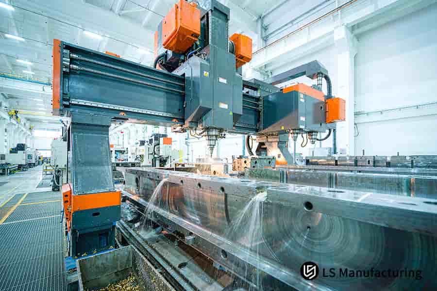
Figure 3: OEM CNC milling and boring service uses Vc 160 m/min.
How Is CNC Machining Cost Managed On Large OEM Parts?
CNC machining cost on large OEM parts is a per-part number that reduces 28.65% when air cutting time and scrap loss are managed. CAM toolpath simulation and roughing-finishing fixtures bring down your one-part price from $1,850 to $1,320. Scrap avoidance protects the plate stock and welding hours already sunk into each full-length weldment.
Where Air-Cutting and Scrap Losses Inflate Your Bill
Scrap loss rules large part CNC machining economics in terms of welded frames. Cost of plate material and 40 hours of welding are lost when one medium-sized weldment fails inspection. Air cutting (non-cutting rapid traverse) is responsible for the rest of your price:
How CAM Verification Cuts Minutes Per Part
Cycle time reduction starts within CAM verification, before any spindle is even turned on. Tool paths simulated without any air moves maintain Vc at 160 m/min, and feed rate is 0.18 mm per tooth with 6 mm axial depth of cut.
ISO 8688-1:1989 is used for tool life testing; thus, wear curves will allow us to make insert change predictions in batches. Common roughing-finishing fixture systems will save you one fixture creation cost from the total tooling cost, while repeats will use the same fixture setup.
What Info Is Critical To Get A Fast CNC Machining Quote?
A CNC machining quote relies on completeness of the drawing, where GD&T information, material grades, and heat treatment state determine the speed at which your RFQ passes the process review stage. Any missing information will result in clarification emails, while complete packages of STEP/DWG files will return a DFM review and pricing tiers within 2 h.
A Five-Step Submission Package
- Export STEP AP242 and DWG files with GD&T according to ASME Y14.5-2018.
- Include maximum span, 6,000 mm, and weight of single piece, 12 t, in the title block.
- Label each welded component view with sling points and lifting center of gravity.
- Specify post-weld annealing condition and required furnace soak period.
Why Incomplete Drawings Delay Pricing
A heavy machinery RFQ package for heavy machinery, which lacks a center-of-gravity marking for lifting, halts the planning process, as crane travel paths remain unspecified. Welded frameworks, lacking an annealing specification, force estimators to speculate about furnace times.
Material grades, such as ASTM A572 Gr. 50, allow estimators to retrieve cutting times from Machinery's Handbook 31st Ed. Your CNC machining RFQ process moves from 2 h to 3 days once clarification loops begin. A DFM analysis quote with tiered pricing becomes possible if GD&T, material grade, and heat treatment condition are specified simultaneously. Bottom line, one missing callout takes away 2 working days from your project before cutting starts.
Data source: LS Manufacturing 2025–2026 automated DFM 3D/2D drawing parsing log (sample size >1,200).
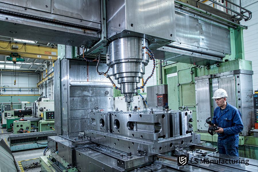
Figure 4: Heavy machinery OEM CNC machining service checks 6 m parts.
How Can Custom Heavy Machinery Parts Pass Strict Metrology?
Custom heavy machinery parts pass strict metrology through a full-size-chain digital survey covering the complete bore-axis spacing of a chassis-length frame. Hand gauges have a reach of 1.5 m. Reports from laser trackers and on-machine touch probes are MPEE calibrated, and each shipment includes one audit-ready package for mining-chassis fatigue-life certification..
Metrology Routes Across a Chassis-Length Span
| Metrology route | Measuring reach | Bore-axis proof |
| Hand gauges (caliper, dial bore gauge) | 1.5 m | Local diameters only |
| Bridge CMM bench | 4 m envelope | Bores inside envelope |
| Portable laser tracker | 6 m+ | Full-chain digital survey |
Laser tracker metrology (a portable laser-based coordinate measuring device) creates one global coordinate system per bore center maintaining MPEE of 15 μm + 6 μm/m. CNC machining metrology report then completes the datum chain, and final bolting is done without rail seat shimming.
On-machine touch probe (spindle-mounted contact probe) verifies the bores pre-release. Corrections take place while the weldment is still clamped. A large part CMM bench measures the bores within a 4 m envelope, and the tracker measurements fill in the rest of the gap. Coaxiality specifications use the ISO 1101:2017 geometrical tolerancing standard for form and position. Your CNC machining tolerance verification document has no measurement gap in the incoming inspection.
Data source: Portable laser tracker official volumetric accuracy calibration report (measurement indication error MPEE calibration).
Case Study: LS Manufacturing OEM CNC Machining For Mining Excavator Chassis: Precision Line Boring And 6 m Gantry Milling
OEM CNC milling and boring on the 6,000 mm mining excavator chassis takes place with the help of one setup gantry machine, where hinge-bore coaxiality is controlled by mid-process stress-relief and hydraulic adaptive fixturing. Re-work reduced by more than 12 percentage points in one batch. Your fleet receives fatigue life certification in compliance with ISO 9001:2015.
Client Challenge
A mining excavator chassis at 8.6 t arrived from the previous vendor with slewing ring seats out by 50 μm from flatness.
Re-clamping segment by segment on a medium-sized boring mill resulted in 14.5% assembly rework.
Spend reached $1,850 per chassis, so CNC machining ROI stayed negative across 28-day cycles.
LS Manufacturing Solution
Initial roughing tests showed that the weldment surface rose 0.12 mm after 70% stock removal when 70% of surface metal was removed.
Process stopped cutting, placed a soak heat treatment at 580°C and changed to hydraulic adaptive support system.
BT50 spindles started operating with Vc = 160 m/min and fz=0.18mm/z.
Results and Value
Flatness across the full chassis span settled inside the tolerance band demanded by slewing-ring seats. Bore walls reduced their roughness by half to achieve an Ra 0.8 μm with 5 microns of coaxiality.
Rework fell to 2.1%, and the price of each chassis came down to $1,320, which was a 28.65% drop compared to the initial cost of $1,850 based on annealing and one fixture finishing.
The chassis bolted straight onto the line with zero shimming — first time in three supplier generations,' says the assembly engineering lead at the mining OEM.
Delivery reduced to 16 days, 42.86% faster, using ultrasonic DT (non-destructive testing) and laser-tracking surveys to complete all traceability reports. Fatigue life validation of mining equipment CNC machining programs through the OEM’s external quality audit release.
Data source: LS Manufacturing measured database project log (project ID #AUTO-2026-882, project log #AUTO-2026-882 spanning >1,200 recorded jobs).
Submit your mining or construction chassis design for a single-clamp gantry feasibility review — our engineers will assess your weldment weight, bore span, and annealing requirement, then model the expected flatness and coaxiality improvement based on the #AUTO-2026-882 process baseline.

FAQs
1. Can LS Manufacturing achieve ±0.02mm across full 6m workpieces?
Yes. One continuous flatness band runs the entire length of an oversized weldment under laser interferometer spatial compensation on a fixed-beam gantry centre. Dated compensation records and constant temperature measurement help incoming inspection crews verify the tolerance target before payment approval.
Data Source: LS Manufacturing Measurement Database
2. How do you prevent stress deformation when milling heavy welded structures?
Between roughing and finishing operations, stress relief annealing relieves the stress stored in the thick plates before the final machining pass. Hydraulic multipoint adaptive support system ensures the welded frame remains in a free condition during the cutting process, while there is no spring back after the clamping release in the milled deck. CNC machining warpage control keeps the bearing bores in place, thus eliminating the need for shimming in assembly.
Data Source: ASME Y14.5 Standard
3. What is the typical lead time for large custom heavy machinery parts?
A 6 m welded chassis typically ships in 16 days from DFM approval (project #AUTO-2026-882 baseline), versus the 28-day cycle with conventional multi-lift boring. Records of project #AUTO-2026-882 illustrate welded housings being delivered to the OEM assembly lines, fully ready to bolt down, without any need for the weld assembly grinding process.
(Project No. #AUTO-2026-882)
4. How does LS Manufacturing inspect large part geometries beyond CMM limits?
A portable laser tracker along with machine-mounted touch probe systems capture the full size chain of the welded structure in one global coordinate system. Bore axis distance, coaxiality and rail seat locations get delivered to the incoming inspection station as one single point cloud file, thus completing the datum chain prior to the assembly process. Re-inspection support and point cloud files are maintained post-delivery for fatigue life evaluation and warranty claims validation.
Data Source: Laser Tracker Calibration Report
5. What surface roughness can be achieved in deep hole line boring?
Long hinge bores, free of chatter marks, are bored using damped anti-vibration boring bars that have a double-end concentric centring. Bores finish at Ra 0.8 μm — two grades finer than the as-welded surface, and the bearings are press-fitted using full-contact surface. Bores, with full contact on each one, eliminate the line reaming operation, extending the servicing intervals in heavy digging cycle.
6. Can you handle heavy equipment parts weighing over 8 tons?
Overhead gantry cranes and heavy duty load-bearing work tables are used for the 8-ton class mining weldments for one lift only. Single lift operations keep crane rentals and lifting equipment upgrades out of capital cost budgeting, and rail seats remain co-planar after the finishing operations. 8-ton class heavy weldments require no mid-process turnover operations.
7. How can engineering teams reduce CNC machining costs for 6m frames?
General tolerances on non-assembly surfaces allow tight tolerances only on surfaces that are machined in one clamp-up position. LS Manufacturing conducts a CNC machining drawing evaluation for all STEP and DWG packages prior to cutting and detects any overspecification of surfaces.
8. How fast can I receive a DFM feedback and machining quote?
All-in-one STEP or DWG package with GD&T callouts, material grade, and heat treatment state gets past process evaluation in one pass. LS Manufacturing provides a DFM feasibility analysis and tiered pricing offers hours after each upload, and any uploaded drawings remain secured by a signed NDA. Even a prototype and a batch of units do not face any MOQ for an initial inquiry.
Request a firm quote for your 6 m+ chassis weldment — we will allocate fixed-beam gantry capacity with BT50 spindle, hydraulic adaptive fixturing, and dual-end concentric line boring, delivering first article with full laser tracker survey report and ISO 286 H7 bore certification.
Summary
With stress relief scheduling, BT50 load control, and laser tracker measurement, five-face fixed-beam gantry centres hold 20 μm-class flatness and 0.8 μm bore finishes across chassis-length weldments. OEM assembly line receives frame assemblies that bolt together without shimming, meaning there will be no tolerance stacking after the machining process.
All-in-one STEP or DWG package with GD&T callouts, material grade, and heat treatment state provides a DFM feasibility assessment and tiered pricing offers hours after uploading through the quote button below. Procurement departments set the tolerance once prior to releasing the tooling budget, and project timelines get rid of extra days that flipping takes.
📞Tel: +86 185 6675 9667
📧Email: info@lsrpf.com
🌐Website: https://lsrpf.com/
Disclaimer
The contents of this page are for informational purposes only. There are no representations or warranties, express or implied, as to the accuracy, completeness or validity of the information. It should not be inferred that a third-party supplier or manufacturer will provide performance parameters, geometric tolerances, specific design characteristics, material quality and type or workmanship through the LS Manufacturing network. It's the buyer's responsibility. Require parts quotation. Identify specific requirements for sections. Please contact us for more information.
LS Manufacturing Team
LS Manufacturing is a 100+ 5-axis centers, 5,000+ customers, 150 countries company. Focus on custom manufacturing solutions. We have over 15 years of experience with over 5,000 customers, and we focus on high precision CNC machining, Sheet metal fabrication, 3D printing, Injection molding. Metal stamping, and other one-stop manufacturing services.
Our factory is equipped with over 100 state-of-the-art 5-axis machining centers, ISO 9001:2015 certified. We provide fast, efficient and high-quality manufacturing solutions to customers in more than 150 countries around the world. Whether it is small volume production or large-scale customization, we can meet your needs with the fastest delivery within 24 hours. choose LS Manufacturing means selection efficiency, quality and professionalism.
To learn more, visit our website: www.lsrpf.com

