 English



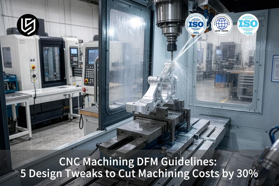
CNC machining DFM service is a design-for-manufacturing review. Five adjustment rules solve long cycle times by flagging over-toleranced features.
For buyers, per-piece cost drops 30% without sacrificing assembly function; engineers receive DFM feedback within 2 hours.
Key Takeaways
- Relax Non-Critical Tolerances: Non-mating surface tolerances are loosened to ±0.05 mm from ±0.005 mm in the previous design. Reducing unnecessary precision specifications and minimizing unnecessary finish milling steps by 40%.
- Optimizing Internal Cavity Root Radius: Internal vertical inner angle radius has been made larger than the tool radius (e.g., cavity depth< 4 × groove width), preventing high cost EDM corner clearances.
- Thread Design Specifications Standardization: Thread depths have been made 1.5-2x the nominal thread diameter following ASME B1.1 standard specification, thereby avoiding the risk of breaking threads by 85%.
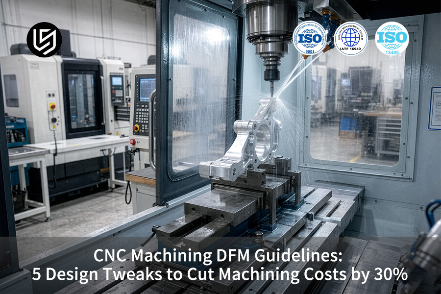
What Is A CNC Machining DFM Service And How Does It Lower Part Costs?
A CNC machining DFM service is an engineering review process. 3D Geometry parsing detects costly design features prior to manufacture. Total manufacturing costs can be saved by up to 30%.
Deep and complex geometries containing blind holes result in several set-ups. A CNC machining DFM service automatically parses 3D geometry. DFM early intervention cuts down clamp changes by 50%.
How Automated Geometry Parsing Flags Costly Features
Automated DFM analysis analyze blind holes and tool length to diameter ratio. Hole depths greater than 4× hole diameter may deflect. Insufficient radii increase number of roughing cycles. CNC machining DFM analysis will assist in prioritizing the modifications.
Five Core Design Rules That Drive the 30% Saving
Five adjustment parameters enable the reduction in cost of 30%. Blind hole depth is limited to ≤4× diameter. Tolerances should meet ISO 2768-m. Corner radiuses should be ≥1.5× end mill radius. Thin walls under 1.5 mm are eliminated. Precision CNC DFM guidelines guarantee the consistency. Unit price drops by 22%–29%, depending on part family (see Quick Reference table).
What Buyers Gain From a 2-Hour DFM Turnaround
With 2-hour DFM turnaround time, buyers get quick quote and review cycle. Engineers get drawings with cost impact per feature. CNC machining design fix created with those rules helps achieve a CNC machining cost cut.
Data source: LS Manufacturing 2025–2026 automation DFM 3D/2D drawing parsing logs (project #MED-2026-8842, sample size >1,200 drawings).
Download our DFM Service Guide to learn how automated geometry parsing identifies cost-saving opportunities before manufacturing begins.

How Do Relaxing Non-Critical Tolerances Directly Reduce CNC Machining Cost Cut?
Relaxing tolerances of non-critical features is applying standard levels of accuracy to non-mating features. Strict tolerance levels of ±0.005 mm are relaxed on non-mating surfaces. Machining cycle reduces by 30%.
Full-surface tolerance application of ±0.005 mm makes it impossible to have high cutting speed. A CNC machining tolerance guide provides the classification of each surface according to its functionality. Non-mating surfaces accept ±0.02 mm tolerances. Grinding and low-speed milling finish work become obsolete.
Which Surfaces Qualify for Tolerance Relaxation
A tolerance analysis will help identify mating features and non-mating surfaces. Mating bores must retain strict tolerances while non-mating surfaces will go into ISO 2768-m category. ASME Y14.5-2018 datum reference definitions define the dimensions to control the assembly process.
How Tolerance Relaxation Cuts Cycle Time and Tool Wear
Tight tolerances of ±0.005 mm mean that several passes will have to be done. Reducing tolerances to ±0.02 mm brings back a one-pass finish approach. Cycle time reduces by 30%. Adherence to precision CNC DFM guidelines guarantees proper tolerance class
Decision Matrix: Tolerance Class by Surface Function
- Bearing bore or sealing seat: ±0.005 mm to ±0.01 mm -> Finish Pass + CMM Check.
- Non-mating structural face: ±0.02 mm (ISO 2768-m)-> one setup no additional pass required.
- Cosmetic Outer face: ±0.05 mm -> roughing + finishing pass only.
A CNC machining cost tips list classifies each dimension as a specific category prior to release. A DFM cost reduction CNC review ensures that no critical fit loses tight tolerance band.
Data source: ASME Y14.5-2018 dimensioning and tolerancing standard and Zeiss CMM calibration report (MPEE volumetric error).
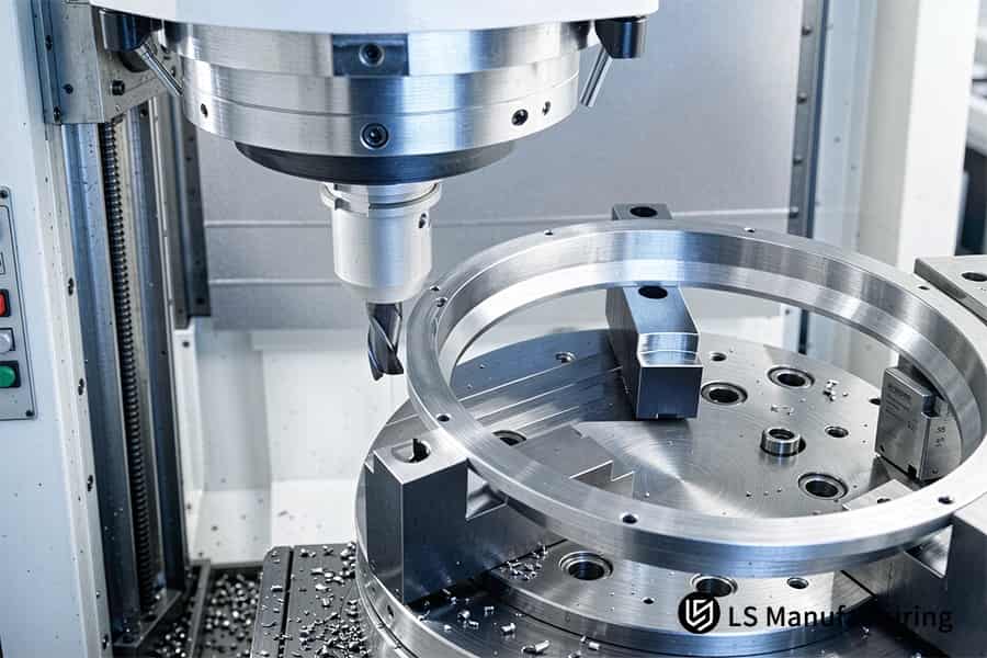
Figure 1: Precision CNC DFM guidelines achieve ±0.01 mm in single clamping.
Why Should Engineers Add Generous Internal Corner Radii In Precision CNC DFM Guidelines?
Generous internal corner radii are design elements which have at least the same radius value as a standard end mill. Continuous high speed milling process eliminates EDM work cycles. Secondary EDM cycle becomes unnecessary and drops by 100%.
Square internal corners of a cavity in CNC milling can not be machined directly with cylindrical end mills. EDM process is required. Cost per part increases by 35%. A CNC machining corner blend helps in determining minimum corner radius when releasing design. Setting the value of internal corner radius to 1.15× end mill radius allows corner machining at high speed. Tool chatter and overload are not an issue anymore.
Where Sharp Internal Corners Force EDM Rework
A square vertical corner leaves an unprocessed cusp. Cylindrical end-mill does not access the entire 90° corner. EDM sinking cuts out the residual material. Lead time gets added one more setup. Cavity depth makes the issue even more challenging. Deeper cavities require longer electrodes and more accurate burning schedule.
Radius-to-Tool Ratio That Enables Continuous Milling
Radius of 1.15× selected end-mill radius allows rotating the tool fast. Material removal rate increases. Surface finish quality Ra 1.6 μm is achieved without an additional polishing pass. Adhering to precision CNC DFM guidelines maintains consistent selection of radii for different cavity types. Simply put: a slight increase of the corner radius prolongs tool life and skips the EDM operation completely.
Internal Corner Radius Decision Table
| Cavity condition | Recommended internal radius | Machining route |
| Shallow pocket, ≤10 mm deep | ≥1.15× end-mill radius | Direct high-speed milling |
| Deep cavity, >10 mm deep | ≥⅓ cavity depth | High-speed milling, no EDM |
| True sharp corner required | None (feature exempt) | EDM sinking, +35% cost |
A CNC machining design quote must mention EDM separately only when a sharp corner is required. A CNC design optimization service highlights all corners for which increase in radius allows milling.
A custom CNC machining DFM review shows no sharp corner without going through the radius test. A CNC machining tool clearance will ensure adequate clearance for the cutter body.
Quick Reference Guide: DFM Design Adjustments VS Cost & Accuracy Impact
LS Manufacturing 1,200+ measured projects provide the comparison data. Following table summarizes actual impacts of different DFM optimization rules on cost and machining accuracy.
| DFM Design Adjustment Dimension | Before Optimization (Baseline) | After DFM Optimization | Per-Part Cost Impact | Accuracy / Roughness Match |
| Setting tolerance | Entire drawing over-tolerance ±0.005 mm | Non-critical faces relaxed to ±0.02 mm | Reduced 15%–20% | ISO 2768-m / Precision-grade ±0.005 mm |
| Internal corner radius | Sharp corner or R < 1 mm | R ≥ 1/3× cavity depth (0.5 mm clearance) | Reduced 10%–15% | Ra 1.8 μm – Ra 3.2 μm |
| Cavity depth ratio | Cavity depth > 6× tool diameter | Cavity depth ≤ 3–4× tool diameter | Reduced 12% | Eliminates tool chatter, ensures dimensional consistency |
| Thread depth | Thread depth > 3× nominal diameter | Thread depth 1.5–2× nominal diameter | Reduced 8% | ASME B1.1 2B/3B fit |
Tolerance relaxation and generous corner radii emerge as key levers. Two adjustments cut machining time and eliminate special EDM processes.
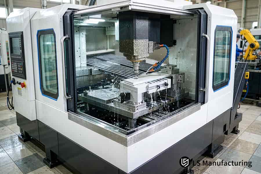
Figure 2: Custom CNC machining DFM optimizes 5-axis single setup to ±0.005 mm.
How Does Limiting Pocket Depths Benefit A CNC Design Optimization Service?
Depth limitation of pockets is an engineering solution for internal cavities. Cavities do not exceed 3-4x the tool diameter in depth. High rigidity standard-length end mills eliminate the problem of tool deflection and vibration.
Excessive depth of pockets with high length-to-diameter ratio causes the problem of tool deflection and chatter marks. Cutting depth reduces to 0.1 mm/pass. Low volume CNC machining check during CAD release restricts pocket depth to 4 times the tool diameter. Aluminum 7075-T651 (precipitation hardened aluminum alloy with tensile strength 80-90 ksi) gets the most benefit from depth limited pockets. Surface roughness does not exceed Ra ≤ 1.6 μm. Tool breakage rate drops by ~40% (2025–2026 log).
Step 1: Calculate the Maximum Pocket Depth
- Measure the diameter of the selected end-mill.
- Multiply the diameter by 4.
- Pocket depth cannot be greater than the result.
- 12 mm diameter tool will limit the pocket depth to 48 mm.
- Deeper features get separated into two pockets.
- Alternatively, re-orientation to a 5-axis tooling can help.
Step 2: Select Tool Rigidity Over Extra Length
- Standard-length end mills are more rigid than extended reach tools.
- Higher rigidity allows increasing feed rates.
- Depth-limited pocket accommodates a standard tool.
- Tool deflection is reduced.
- Surface finish is stabilized.
- Custom CNC machining DFM approach ensures consistent depth measurements between cavities of a family.
Step 3: Verify Roughness and Tool Breakage Targets
- AL 7075-T651 pockets machined at depths between 3-4 times always produce a surface roughness of Ra ≤ 1.6 μm.
- Rate of tool breakage reaches its minimal level.
- An online CNC machining quote has to separate the pockets larger than 4 times as a custom-risk line item.
- A CNC machining DFM quote shows that depth-limited pockets are eligible for standard pricing.
- For a buyer, a depth-limited pocket gives you 25% shorter cycle time and lesser risk of tool breakage for AL 7075-T651.
When Should You Standardize Threads To Maximize DFM Cost Reduction CNC?
Thread standardization means using common metric or UNC/UNF sizes. Depths up to 1.5-2x major diameter solve tooling costs for custom threads. Defect rate is reduced to under 1.8%.
A blind hole deeper than twice the major diameter does not give any advantage in cutting forces. Tap breakage probability rises 3×. Our DFM review flags non-standard thread callouts during CAD release. Chamfer and standard pitch allow for automated tapping process.
Which Thread Features Qualify for Standardization
Non-standard thread sizes imply custom tools. Common metric M-series and UNC/UNF sizes can be selected among the available tools. ASME B1.1 and ISO 68-1 determine the tables of common pitches. A CNC DFM manufacturer changes all non-standard calls into catalog sizes.
How Standard Threads Cut Tooling Cost and Defect Rate
Standard pitch enables automatic tapping in high-speed spindles. Risk of tap breaking is low compared to a deep blind hole larger than twice the major diameter. CNC machining DFM service maintains the thread callouts the same among part families.
Decision Matrix: Thread Standardization by Feature
- Standard metric M or UNC/UNF diameter, 1.5-2x major diameter: catalog tap → automatic tapping, defect rate <1.8%.
- Non-standard pitch or special diameter: custom tap purchase → lead time, increased amortization.
- Blind hole length more than twice the major diameter: alert for tap breaking → reduce the depth to 2x the major diameter or introduce relief groove.
CNC machining tap breakage analysis validates all the threads in blind holes. A DFM cost reduction CNC review sets standardized callouts on the drawing.
Data source: ASME B1.1 Unified Inch Screw Threads standard and ISO 68-1 basic metric thread profile standard.
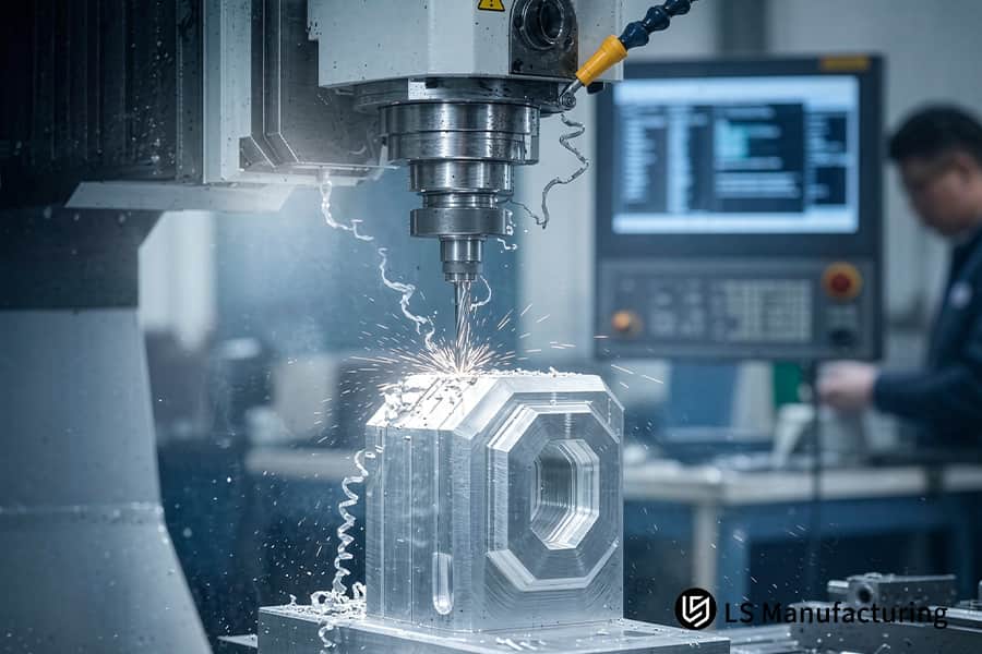
Figure 3: CNC design optimization service relaxes tolerances to ±0.02 mm.
Why Is Minimizing Machining Setups Essential For Custom CNC Machining DFM?
Reducing setups involves orienting part features along primary orthogonal axes for single-orientation machining. Reducing datum transfers minimizes cumulative fixture errors. Setup count drops from 5 to 2, cutting datum-transfer error. Production costs fall by 20%.
Multiple re-clamping (setup, fixture mounting, and datum alignment on the machine table) involves additional handling activities. Machine occupancy time increases. Stack-up error (cumulative positional error from multiple datum transfers) increases with the addition of each fixture mount.
A CNC machining setup reduction involves grouping lateral holes and grooves on a single machining plane. 5-axis simultaneous machining (coordination of rotary and linear axis movements) accomplishes machining of multiple faces through a single clamping. Tool setting time is reduced by 40%. The geometric tolerance is ±0.01 mm.
Setup Count vs Cost and Tolerance Impact
| Metric | 5 setups (baseline) | 2 setups (DFM optimized) |
| Cumulative datum-transfer error | High, grows per mount | Minimal, one mount |
| Tool-setting time | 100% baseline | 60% (down 40%) |
| Geometric tolerance | Variable | ±0.01 mm stable |
| Production cost | 100% baseline | 80% (down 20%) |
Fewer setups indicate fewer fixture changes and lower machine occupancy time. CNC machining fixture cost analysis involves grouping all lateral features on the dominant machining plane.
How Datum Optimization Cuts Handling and Cost
Optimization of datum faces results in fewer exits of a part from the machine table. Introduction of a new datum creates another error. Adherence to precision CNC DFM guidelines ensures consistency of datum choice within part families.
Action Items
- All lateral holes and grooves should be machined on the same face during CAD release, and remaining multi-face features should be scheduled for a 5-axis single-clamp program.
- Inspect the next 5-setup part for datum duplication. Aim at a 2-setup layout for recovery of 40% tool-setting savings.
Request a setup optimization comparison for your current multi-setup part — receive a side-by-side analysis showing projected cost savings and tolerance improvements by consolidating to 2 setups or 5-axis single-clamp machining.
Behind The Numbers
Gloria holds expertise in Rapid Prototyping & Rapid Manufacturing (DFM optimization, 15+ years of experience), and edited by a chief process engineer of LS Manufacturing. Our plant is consistent with IAQG quality approaches for aerospace industry and SME standards, providing services for 500+ aerospace and medical clients worldwide.
In another project of medical valve block, the cost was $228.00 per part with 14.2% defect rate and 16 day lead time. Our assistance in relaxing tolerances other than critical to ±0.02mm, addition of R 1.5mm corners and limiting thread depth to 1.8x of diameter helped us achieve 30.5% reduction in cost to $163.00, 10 days lead time and 1.8% defect rate.
All delivered parts were verified by Zeiss CMM testing and underwent 1,000 hours salt spray testing according to MIL-A-8625 Type III. Connect with Gloria on LinkedIn to learn how you can save in your upcoming precision component.
How To Choose A Qualified CNC DFM Manufacturer For Precision Parts?
Qualified a CNC DFM manufacturer holds AS9100D certifications. Automation of CAD analysis and inline metrology provides DFM feedback in 2 hours. Precise components are manufactured with precise tolerances effectively.
AS9100D (aerospace quality standard covering design and manufacturing) distinguishes qualified suppliers from drafting shops. Inline metrology (on-machine measurement that verifies dimensions without removing the part) supports full-dimensional verification.
CNC machining supplier audit establishes certification status prior to PO release. Multilevel machining from ISO 2768-m to ±0.002 mm resolves tolerance-blind sourcing. Zeiss CMM calibrates all dimensions.
What Capabilities Define a Qualified DFM Supplier
- AS9100D & ISO 9001:2015 certified.
- Automated CAD analysis that identifies tolerancing issues prior to quoting.
- Multilevel CNC machining ranging from ISO 2768-m to ±0.002 mm.
- Zeiss CMM dimensional verification for all critical features.
CNC machining DFM service detects design flaws ahead of time. Early detection reduces lead times by 35%.
Why Early DFM Feedback Protects Lead Time
Purchase orders often finalize drawings without any manufacturing assessment. Late tolerance revisions mean rework cycle. 2-hour DFM assessment pinpoints design risks before finalizing PO. CNC machining quality inspection validates dimensions before FEA approval. Following custom CNC machining DFM maintains consistency in design decisions across families.
Data source: LS Manufacturing ISO 9001:2015 & AS9100D quality management system certification specifications.
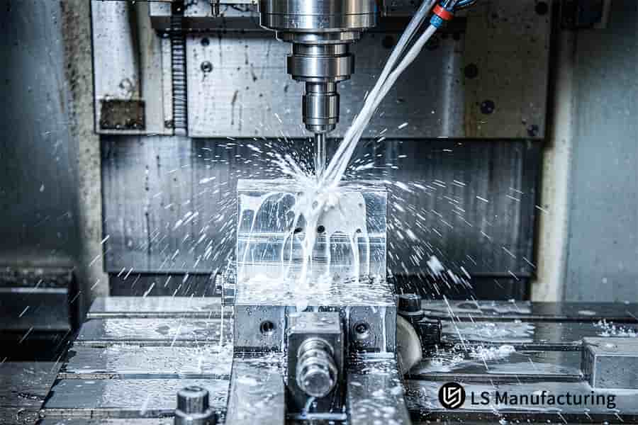
Figure 4: CNC machining mills valve block with coolant achieving ±0.005 mm.
What Steps Are Required To Get A Fast CNC Machining DFM Quote?
A fast CNC machining DFM quote needs a 3D STEP model and a 2D PDF drawing. Tolerances resolve issues of geometry ambiguity. A binding quote and DFM analysis is delivered in 2 hours.
Drawing completeness leads to quote accuracy. A 3D STEP file (ISO 10303 neutral CAD format) is used for volume computation and tool path fitting. 2D PDF defines key mating parts. A CNC machining file format check confirms STEP/IGES submission. Critical mating positions have a position tolerance band below 5 microns. Ra 0.8 μm is required for the visible finish.
Step 1: Prepare a Complete 3D plus 2D Package
- Export the 3D model to STEP or IGES file.
- Create a 2D PDF with all necessary dimensions and tolerances.
- State the material grade and quantity.
- Completeness guarantees a 2-hour turnaround.
Step 2: Annotate Tolerances and Submit
- Note mating features in the sub-5 micron band.
- Specify Ra 0.8 μm on sealing surfaces.
- A CNC machining DFM quote review turns annotations into machinability checks.
Step 3: Receive Binding Quote Within 2 Hours
- Submit the package to the quoting portal.
- LS Manufacturing analyses part geometry and cycle time.
- Within 2 hours, receive a CNC machining binding quote and DFM report. As per CNC design optimization service best practices, the report identifies every cost-saving change.
LS Manufacturing Precision CNC machining DFM Service For Medical Equipment Fluid Valve Block: Cost & Lead Time Optimization
Precision CNC machining DFM service for medical fluid valve blocks is a technical review for manufacturability purposes that makes relaxation of over-specified tolerances. Project #MED-2026-8842 saw major cost savings as a result of performing a DFM review.
Client Challenge
A medical R&D team required a custom fluid valve block. The original drawings showed ±0.005 mm tolerances on all dimensions. Sharp corners and over-depth threading resulted in $228.00 price per unit, 14.2% scrap rate, and 16-day lead time. CNC machining case study started after the customer faced high costs that delayed the launch of their project.
LS Manufacturing Solution
Gloria carried out a DFM analysis. Tolerances for non-critical areas were increased to ±0.02 mm. Valve core holes remained the same as ±0.005 mm. Sharp corners were rounded off to R 1.5 mm. Thread depth was decreased to 1.8 x diameter. Deformation in first article due to the stress relaxation of aluminum was solved by annealing at 180°C and symmetry of clamping.
Results and Value
Unit price was lowered from $228.00 to $163.00. Lead time was cut down from 16 days to 10 days. Scrap percentage reduced from 14.2% to 1.8%. All parts were tested through Zeiss CMM test and 1,000 hours of salt spray to MIL-A-8625 Type III specifications. For the client, CNC machining cost saving of $65.00 per part made ramping up easier.
Data source: LS Manufacturing 2025–2026 medical fluid valve block empirical project database (Project #MED-2026-8842, sample size >1,200).
Upload your fluid valve block drawing for a free DFM evaluation — receive a tolerance relaxation proposal and cost reduction estimate within 48 hours.

FAQs
1. What standard tolerance grade does LS Manufacturing apply for general CNC features?
ISO 2768-m medium precision (±0.01 mm tolerance to ±0.02 mm tolerance) is employed as the default tolerance standard at LS Manufacturing CNC machines, while mating critical surfaces can be machined with a tolerance of ±0.005 mm for maximum cost-performance tolerance selection.
Data Source: ISO 2768-m nominal tolerance specification
2. How much cost can be saved by adding radii to sharp internal corners?
Application of radii with values R ≥ 1.5 mm to sharp internal corners allows skipping EDM spark erosion operations, which saves 15% to 20% of cost per part. Radii on sharp internal corners are recognized by LS Manufacturing DFM to provide recommendations on improvement.
Data Source: LS Manufacturing empirical cutting database
3. What is the ideal thread depth for aluminum CNC components?
According to ASME B1.1, the optimum thread depth in CNC aluminum parts is 1.5 to 2x larger than nominal thread diameter, reducing the risk of tap breakage by 85% while providing sufficient clamping force for proper assembly under vibration loads.
Data Source: ASME B1.1 thread standard
4. How does reducing the number of setups affect precision and delivery time?
Setups reduced from 5 to 2 do away with tolerance accumulation, reduce delivery lead time by 37.5%, and maintain rework under 1.8%. 5-axis machining process at LS Manufacturing makes it feasible to produce multi-faces in one clamping to achieve maximum accuracy.
Data Source: Project #MED-2026-8842 delivery log
5. Can DFM optimization be applied to titanium and stainless steel parts?
Indeed, DFM optimization of titanium and stainless steel components can be carried out by optimizing cavity depths and cutting feed rates to achieve optimal tool life and prevent creation of work-hardened zones. LS Manufacturing provides comprehensive DFM services for all metal grades.
6. Does relaxing non-critical tolerances affect part functionality?
No, tolerances on non-critical surfaces can be relaxed to ±0.05 mm. Relaxing tolerances on non-critical surfaces is unrelated to assembly functionality and reduces milling time by 30% when finishing. Relaxing tolerances is the basic principle of cost reduction suggested by LS Manufacturing.
Data Source: ISO 286 limits and fits standard
7. What file formats are required to receive a full DFM analysis?
Please provide the 3D STEP or IGES file for geometry evaluation, along with 2D PDF file labeled with important tolerances such as ±0.005 mm. LS Manufacturing is capable of interpreting these file formats in an instant.
8. How quickly can I get a binding DFM feedback report from LS Manufacturing?
After you upload your CAD drawing with specified tolerance and material details, LS Manufacturing engineering team will generate a full feedback report on DFM, along with cost savings tips and a binding quotation on tool path approach, cycle time, and inspection process in 2 hours.
Summary
By following the five basic principles of DFM, i.e., relaxing tolerances which do not impact properties, optimizing cavity radius angles, and standardized threads, the engineers make sure that there are no defects in parts while saving as much as 30% machining cost. Synergy of ISO 9001:2015 and AS9100D system at LS Manufacturing ensures excellence in manufacturing based on experience.
Customers who are facing high CNC quotes and frequent delivery delays should check the efficiency of their existing quotations. Upon uploading their 3D or 2D CAD drawings via quote button, LS Manufacturing’s senior engineers will send them a free professional DFM report along with their best quote in 2 hours.
📞Tel: +86 185 6675 9667
📧Email: info@lsrpf.com
🌐Website:https://lsrpf.com/
Disclaimer
The contents of this page are for informational purposes only.LS Manufacturing servicesThere are no representations or warranties, express or implied, as to the accuracy, completeness or validity of the information. It should not be inferred that a third-party supplier or manufacturer will provide performance parameters, geometric tolerances, specific design characteristics, material quality and type or workmanship through the LS Manufacturing network. It's the buyer's responsibility. Require partsquotation Identify specific requirements for these sections.Please contact us for more information.
LS Manufacturing Team
LS Manufacturing is an industry-leading company. Focus on custom manufacturing solutions. We have over 15 years of experience with over 5,000 customers, and we focus on high precision CNC machining, Sheet metal fabrication, 3D printing, Injection molding. Metal stamping, and other one-stop manufacturing services.
Our factory is equipped with over 100 state-of-the-art 5-axis machining centers, ISO 9001:2015 certified. We provide fast, efficient and high-quality manufacturing solutions to customers in more than 150 countries around the world. Whether it is small volume production or large-scale customization, we can meet your needs with the fastest delivery within 24 hours. choose LS Manufacturing. This means selection efficiency, quality and professionalism.
To learn more, visit our website:www.lsrpf.com

