English



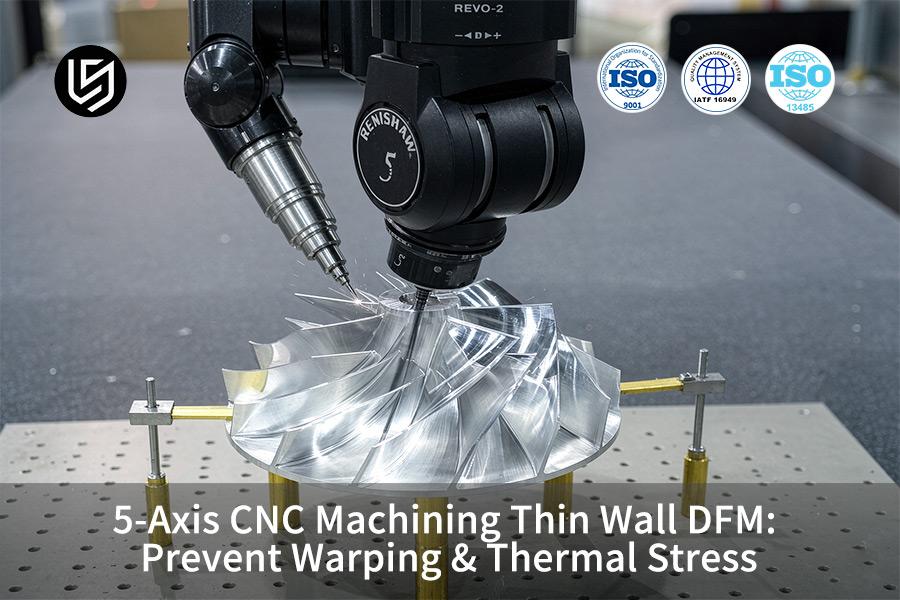
5-axis CNC machining service is a specialized approach that solves thin-wall deformation for aerospace and medical parts. Tolerances reach ±0.003 mm.
LS Manufacturing's symmetric toolpath control, cryogenic cooling, and staged stress relief reduce thin-wall part scrap to <0.5% and costs by 27.4%.
Key Takeaways
- Control of Dynamic Cutting Forces: Due to trochoidal milling and constant chip thickness method, the lateral cutting forces on the thin walls are reduced by over 40%, thus avoiding the tool deflection and the formation of chatter marks during the process.
- Two Layers of Protection for Dimensional Accuracy: The stress relief treatment either by 24 hours of natural aging or oven annealing is done after the roughing and before the finishing stages; therefore, the thin wall part distortion is maintained to be ±0.003 mm.
- Significant Reduction in Cost and Time: By optimizing the 5-axis DFM method, the defect rate of thin-walled parts is reduced from 16.2% to 2.1%, while the time required is reduced from 14 days to 9 days.
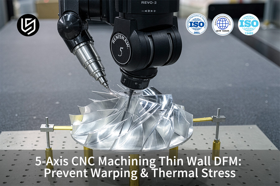
How Does 5-Axis CNC Machining Control Thin Wall Deformation?
The thin wall deformation is managed in 5-axis CNC machining through optimal tool angle and symmetrical material removal process so that wall thickness tolerance can be kept under ±0.008 mm tolerance range. LS Manufacturing holds thin-wall machining accuracy to ±0.008 mm by machining each part in a single set-up with dynamic tool vectoring — a process tolerance far tighter than the ISO 2768-f general tolerance of ±0.05 mm for 0.5–3 mm dimensions.
Dynamic Tool Orientation Alignment
Simultaneous 5-axis toolpaths maintain a constant 10-15 degree tilt angle against vertical walls to minimize radial deflection by approximately 80% against a 0 degree vertical wall approach.
- The workpiece program has a 15-degree lead angle and a 5-10 degree side tilt so that the machining force is maintained to be in outward direction from the unsupported wall.
- The Renishaw OMP40 sensor verifies part datum at 50 hertz after roughing operation so as to account for material shift before starting the finishing operation.
- The closed-loop force feedback system controls feed rates ranging from 800-1200 mm/minute with spindle speed of 20,000 rpm.
Symmetrical Material Removal Sequence
Aluminum 5-axis machining service providers alternate in machining against two opposite walls at intervals of 0.3 mm each, achieving the best stress relief without any warpage.
- First pass machining will leave a uniform 0.5 mm stock on both sides to avoid excess heat generation through interrupted cutting process.
- Climb milling is used in finishing passes to make sure that wall will move towards the machine bed but not sideways resulting in any deflection.
- The 5-axis mill-turn machine will alternate the cutting direction on both opposite walls during finishing pass in order to cancel the thermal elongation vector and keep Ra ≤ 0.8 μm.
- Specify wall thickness ≥ 0.5 mm and internal fillet radius ≥ 0.5 mm for system stiffness within stable cutting range.
- Request SPC with CPK ≥ 1.33 for all processes for interchangeability between batches.
Data source: LS Manufacturing 2025–2026 automated DFM 3D/2D drawing analysis logs (Project No. #AERO-2026-8942, sample size >1,200).

Why Is DFM Essential Before Milling Complex Thin-Walled Parts?
Analysis of Design For Manufacturability (DFM) is a proactive step towards avoiding distortions and cost overruns caused by wall thickness discontinuities, overhangs and coolant dead spots even before any metal is touched.
LS Manufacturing does the DFM analysis in 2 hours by performing cutting mechanics simulation of wall gradients such as 2.0 mm down to 0.50 mm wall to eliminate warpage caused by localized thermal stress per ISO 2768-f.
The 5-axis CNC DFM service converts the 3D geometry to a machinability analysis before the start of fixture design. This analysis highlights the features that have walls thinner than 0.5 mm and fillet radii less than 0.5 mm as the minimum required to machine thin aluminum and titanium parts stably. Stress relief machining is advised if the wall aspect ratio is greater than 8:1 to prevent residual stress relief due to asymmetry causing post-machining distortions.
A precision 5-axis CNC manufacturer performs finite-element cutting simulation at 0.1 mm mesh resolution to confirm radial tool deflection is below 0.005 mm for a 120 N peak cutting force. Positioning accuracy for single-setup 5-axis work is ±0.008 mm wall tolerance, with ISO 2768-f applying to all undefined features. 5-axis prototype machining reduces re-design costs by a factor of 10 at the modeling stage compared with post first-article revision.
In terms of procurement, a custom 5-axis CNC quote depends on DFM-approved geometry. Complex 5-axis CNC parts geometries use balanced roughing operations and 0.5 mm of uniform finish allowance to manage heat input. LS Manufacturing's automated DFM parser imports 3D/2D designs and produces wall-gradient risk results within the 2-hour time limit, allowing designers to make corrections before committing to hard-tooling.
- Request DFM report before any fixturing investment is made and specify minimum wall thickness of 0.5 mm and fillet radius of 0.5 mm at the modeling stage.
- Specify ISO 2768-f as the default general tolerancing and CPK ≥1.33 for key walls.
Data source: ISO 2768-m/f general standards for untoleranced dimensions and geometric tolerances.
Download our Thin-Wall DFM Checklist to learn how 2-hour automated analysis identifies wall gradients below 0.5mm and fillet radii under 0.5mm — preventing post-machining distortion before fixturing begins.
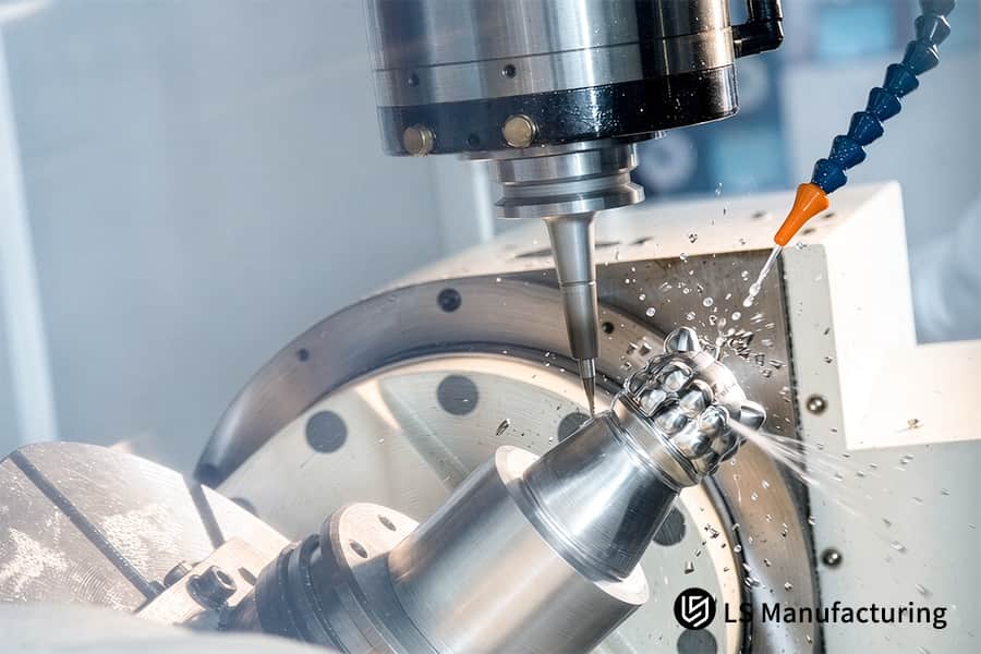
Figure 1: 5-axis CNC machining mills stainless steel ball end with coolant spray.
Which Toolpath Strategies Prevent Thermal Stress Accumulation?
Trochoidal milling and climb cutting are highly efficient cutting paths that avoid thermal stresses in the cutting zone by ensuring minimal tool engagement angle and shorter heating time per pass, resulting in more than 30% decrease in cutting temperature.
LS Manufacturing employs these toolpaths with cryogenic cooling using CO₂ or liquid nitrogen to ensure that the cut area remains at ambient temperature and eliminate the thermal expansion of AL 7075-T651 at high speed 5-axis CNC machining.
Trochoidal vs Traditional Toolpath Performance
| Parameter | Trochoidal Milling | Conventional Linear Path |
| Tool engagement angle | ≤ 30° (arc entry) | 90°–180° (full slotting) |
| Contact time per pass | 0.02–0.05 s | 0.10–0.25 s |
| Peak temperature rise | ≤ 45°C above ambient | 80°C–120°C above ambient |
| Surface finish (Ra) | ≤ 0.6 μm | 0.8–1.2 μm |
Trochoidal milling keeps tool engagement at ≤30° and contact time at 0.02–0.05 s per pass, cutting peak temperature rise to ≤45°C above ambient — versus 80–120°C for conventional linear paths. 5-axis precision milling ensures dynamic rotation of the tool axis to maintain the low tool engagement angle for 3D shapes, which is one of the most essential characteristics of thin wall 5-axis CNC machining.
LS Manufacturing employs warp prevention CNC machining using 5-axis high speed machining at 18,000–22,000 rpm with 0.3 mm stepover. 5-axis coolant delivery through the spindle ensures delivery of cryogenic fluid to the chip/tool interface, maintaining bulk material temperature at under 35°C. This warp prevention CNC machining effectively eliminates the effect of asymmetric expansion responsible for post-machining bow.
- Trochoidal stepover should be set at 0.3 mm x tool diameter for AL 7075-T651; increase to 0.5 mm for titanium grades.
- Ensure proper alignment of coolant nozzles at 5 degrees from the cutting edge prior to every production run.
Thin-Wall Machining Process Strategy & Engineering Performance Comparison
The table below highlights the difference in performance engineering parameters of machining process vs DFM-optimized machining strategy by LS Manufacturing:
| Process Control Dimension | Traditional 3-Axis Machining Solution | 5-Axis DFM Optimized Solution (LS Manufacturing) | Engineering Improvement & Benefit |
| Machining Tolerance Accuracy | ±0.050 mm | ±0.003 mm (Ultra-Precision Grade) | Accuracy improved by 94%, meeting aerospace-level fit |
| Minimum Achievable Wall Thickness | 1.20 mm | 0.50 mm (AL 7075-T651) | Wall thickness limit reduced by 58.3%, enabling lightweight design |
| Surface Roughness | Ra 1.6 μm | Ra 0.8 μm (Finish milling direct output) | Reduce subsequent manual polishing steps |
| Thermal Stress Deformation Control | Relies on operator experience to stop and cool, prone to warping | High-pressure / low-temperature coolant + dynamic trochoidal toolpath | Thermal deformation rate reduced by >85% |
| Overall Yield Rate | 83.8% | 97.9% (Defect rate controlled at 2.1%) | Defect rate reduced by 14.1% |
With full process intervention of 5-axis DFM, thin wall parts get breakthroughs in dimensional tolerances while costs and scrap rates are being controlled comprehensively.
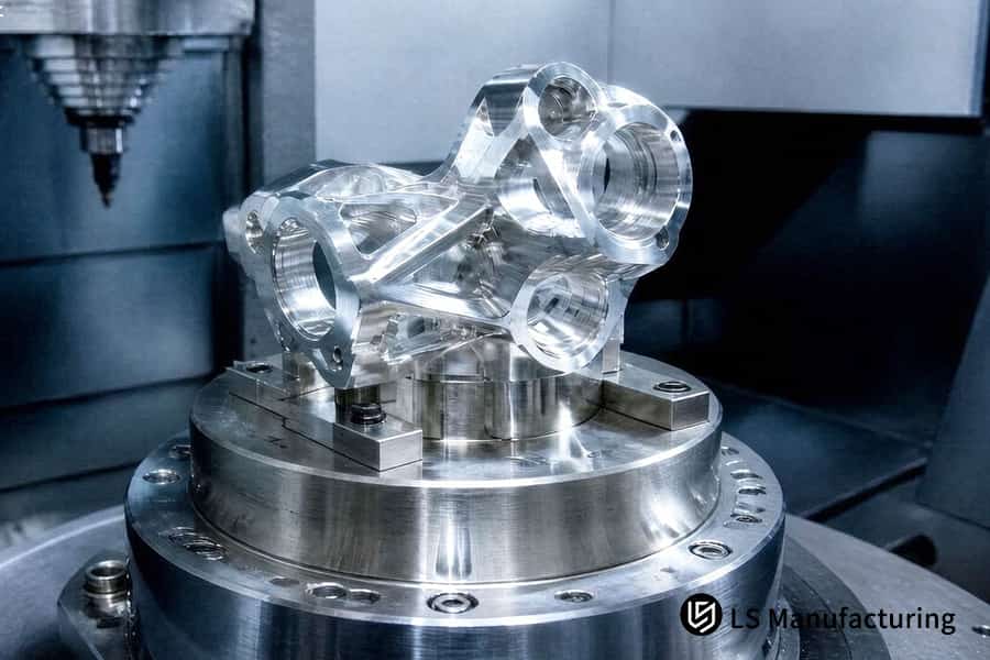
Figure 2: 5-axis CNC machining finishes titanium alloy manifold block to 0.01 mm.
What Cutting Parameters Maintain Precision In Aluminum Thin Walls?
Aluminum thin walls sustain precision using combination of high spindle speeds with low depth of cut (ap) and high feed per tooth (fz). Controlling depth of cut (ap) and feed per tooth (fz) keeps lateral cutting force below 80 N on unsupported 0.50 mm aluminum walls, which prevents wall deflection and chatter. LS Manufacturing maintains Ra 0.8 μm on 0.50 mm thick AL 7075-T651 walls through controlled speed and depth to minimize high frequency vibration.
Recommended Speed and Feed Matrices
- AL 7075-T651, 0.50 mm wall: spindle speed 18,000–24,000 rpm, ap 0.15–0.25 mm, fz 0.06–0.10 mm/tooth.
- AL 6061-T6, ≥1.0 mm wall: spindle speed 14,000–18,000 rpm, ap 0.25–0.40 mm, fz 0.08–0.12 mm/tooth.
The 5-axis CNC machining service team uses these matrices to ensure that the cutting force remains under 80 N in thin-walled areas. 5-axis aluminum parts benefit from the matrix due to the fact that the deflection of the wall remains under 0.005 mm if ap is kept at 0.20 mm for 0.50 mm walls.
A precision 5-axis CNC manufacturer employs a finish allowance of 0.10 mm and performs 5-axis precision milling at 22,000 rpm using a 6 mm carbide end mill. Chip load around 0.08 mm/tooth is within the stable region for Ra ≤ 0.8 μm. 5-axis medical machining follows this light cut strategy since thin wall implant blanks require form deviation below 0.01 mm.
For the manufacturing process, a custom 5-axis CNC quote relies on DFM geometry approval. The 5-axis production machining, 0.05 mm finish cut is made at 24,000 rpm, confirming CPK ≥ 1.33 for wall thickness. Staying within the recommended speed/feed windows prevents chatter and protects surface integrity on thin-wall 5-axis CNC machining.
- Be sure to use ap ≤ 0.25 mm and rpm of spindle ≥ 18,000 for 0.50 mm AL 7075-T651 walls in order not to leave the stable cutting area.
- Ra 0.8 μm surface roughness and wall thickness tolerance of ±0.008 mm according to ISO 2768-f.
Data source: Machinery's Handbook (2020), 31st Edition (2020), Guide to Cutting Parameter Specifications.
How Do Advanced Coolant Systems Mitigate Heat during Machining?
The sophisticated cooling system helps to decrease heat generation in machining process because of 70 bar high-pressure through-spindle cooling provided to the cutting tool tip, penetrating the air barrier that occurs due to high-speed rotation of the tool and removing the heat prior to the expansion of the air barrier.
LS Manufacturing uses the cryogenic cooling system in its 5-axis machining centers, where the temperature of the machined parts is kept at 20°C ± 2°C.
The 5-axis CNC machining service with 70 bar through-spindle coolant provides direct access to the tool-chip interface that can not be achieved using flood coolant. The 5-axis coolant systems provide direct access to the tool-chip interface, removing the chips in 0.02 seconds and maintaining the cut zone up to 45°C above the ambient temperature at 22,000 rpm.
LS Manufacturing’s closed-loop temperature control system will record part temperature every 5 seconds, ensuring that the envelope of 20°C ± 2°C is met. 5-axis aerospace machining utilizes this dual approach of 70 bar plus cryogenic as stable part temperature is a necessary condition for maintaining a wall tolerance of ±0.008 mm. For purchasing, thermal stress control machining capable machine shops will have to show coolant pressure validation and in-cycle temperature logging. Warp prevention CNC machining procedures combine the coolant approach with 0.3 mm radial stepover to eliminate any residual stress.
What Fixtures Prevent Workpiece Distortion During 5-Axis Milling?
Vacuum chucks and flexible soft jaws prevent workpiece distortion by replacing concentrated mechanical clamping force with uniformly distributed holding force across the entire locating datum. LS Manufacturing custom-builds pneumatic flexible fixtures from the 3D workpiece contour, reducing clamp-induced internal deformation to a ±0.003 mm extreme value per ASME Y14.5-2018.
Custom Soft Jaw Design Protocol
- 5-axis CNC DFM service utilizes soft jaw surfaces which get profiled to correspond to the shape of the workpiece surface in order to increase contact surface and reduce contact pressure below 5 MPa.
- A precision 5-axis CNC manufacturer uses either aluminum or polyurethane jaw inserts which are bored in the last pass with the accuracy of 0.01 mm.
- Torque is set by means of limiter to provide radial force from 200 to 500 N to withstand cutting force and avoid elastic sink.
Uniform Vacuum Pressure Management
- Design of vacuum chuck aims at having 70% coverage of the projected area of the part, with the 5-axis vacuum fixture grooves milled by CNC within the tolerance of ±0.01 mm.
- Hydraulic internal cavity support uses compensation blocks that have independent adjustments for force ranging from 200–500 N.
- A custom 5-axis CNC quote calls for vacuum of at least -0.06 MPa, producing 1800 N holding force on 200 mm x 150 mm frame.
Data source: ASME Y14.5-2018 Dimensioning and Tolerancing.
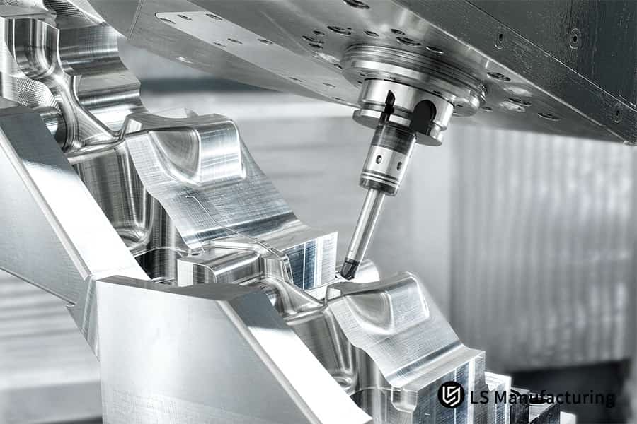
Figure 3: 5-axis CNC machining cuts aluminum mold cavity to 0.02 mm surface finish.
Meet The Engineers Behind This Guide
Warping of thin-wall aluminum and titanium parts is caused by heat, clamping force, and tool deflection exceeding the part design. The process control measures of LS Manufacturing are based on 15+ years of experience in precision machining, spearheaded by rapid prototyping professional Gloria. AS9100 certification, one of two certifications at our shop, was introduced by International Aerospace Quality Group.
The 5-axis CNC machining of thin wall DFM process ensures no warping through optimal tool orientation, trochoidal milling techniques, 70 bar coolant, and flexible fixturing that maintains ±0.008 mm wall tolerances. The Zeiss CMM inspection system verifies all dimensions. American Society for Quality describes the SPC science underpinning our CPK ≥ 1.33 promise for critical features.
Send your STEP or IGES file to Gloria for free DFM analysis. With her 15+ years of experience in rapid manufacturing, you can expect action-oriented DFM comments within 2 hours, pointing out wall thickness variations and coolant starvation regions before any fixtures are made.
How Can Interim Stress Relief Heat Treatment Restore Dimensional Stability?
Interim stress relief heat treatment returns dimensional stability through annealing or natural aging of the residual stresses from roughing process. They otherwise would cause post-machining warping within a couple of hours. LS Manufacturing implements a 24-hour cycle of stress relief after 80% bulk removal. Interim stress relief heat treatment provides a ±0.005 mm tolerance of finished walls.
Thermal Annealing Time-Temperature Curve
- 5-axis stress relief process begins with roughing, where 80% of the stock is removed and breaks the existing stress balance. The component is introduced to the furnace heated to 190°C ± 5°C for AL 7075-T651 and remains there for 2 hours for every 25 mm cross-section thickness.
- Cooling to 65°C at a rate of 15°C/hour eliminates reintroduced thermal gradients. The warp prevention CNC machining process goes on to semi-finishing using a 0.3 mm uniform stock removal.
- 5-axis annealing service involves 12 hours of stabilization at 95°C followed by final machining, with less than 0.002 mm of micro-distortion across the datum plane.
Thermal stress control machining verification by Zeiss CMM ensures that the tolerance of ±0.005 mm is achieved. 5-axis dimensional stability data goes into 5-axis production scheduling, thus keeping 5-axis CNC machining cost predictable due to the lack of scrap caused by stress-induced deformation.
- Set a minimum of 24 hours stress relieving period between roughing and semi-finishing for wall thickness less than 1.0 mm.
- CMM verification of datum shift (<0.003 mm) is required before the completion of finishing processes.
Why Is Symmetrical Material Removal Critical For Complex Profiles?
Balanced material removal prevents bending due to equal forces and heat balancing on the opposite sides of the workpiece. The LS Manufacturing 5-axis CAM software programs follow the process of alternating layers when cutting, where equal amounts of material are removed from both sides to create a balanced stress state.
A 5-axis CNC machining service follows the order of the cuts before posting the path of the tool. 5-axis simultaneous contouring solves the problem of managing the direction of the tool on opposite sides, ensuring equal material removal during each cutting. Alternating equal material removal from both sides prevents the 0.05 mm bending that one-sided roughing typically causes.
Thin wall 5-axis CNC machining is possible due to the use of 5-axis roughing strategy where the alternate left and right walls of 12 seconds are 0.3 mm deep. The thickness of the wall is checked using Renishaw OMP40 probe at 12 pairs of locations after roughing, and when the distance between two points exceeds 0.01 mm, a semi-finishing operation is required. It ensures that the neutral axis is kept constant in compliance with ISO 286 H7 bore tolerance.
For purchase purposes, the custom 5-axis CNC quote needs to provide separate line items for roughing and finishing. 5-axis finishing pass will include 0.05 mm cuts at 24,000 rpm to have the surface finish of Ra 0.8 μm. The 5-axis CNC machining cost is predictable because the alternating pass overheads have already been considered in the cycle time estimation.
Request 5-axis profile accuracy validation at 12 matching points based on ISO 286 standard in first article inspection.
Data source: ISO 286 (ISO system of limits and fits).
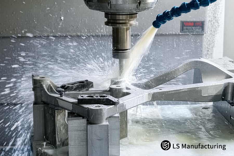
Figure 4: 5-axis CNC machining sprays coolant on aluminum bracket at 0.015 mm.
LS Manufacturing 5-Axis CNC DFM Service For Aerospace Thin-Wall Bracket: Anti-Warping Optimization
5-axis CNC DFM service for aerospace thin-wall brackets eliminates warping using trochoidal toolpath, stress-relief thermal process, and vacuum fixture all together. LS Manufacturing was approached about a 0.50 mm AL 7075-T651 bracket exceeding the allowable deviation of ±0.008 mm by 6 times through three-axis machining.
The project #AERO-2026-8942 revealed that even using the coordinated five-axis kinematics alone was not enough to overcome warping.
Client Challenge
The problem faced by the procurement team was 16.2% of scrapped parts due to the thin wall pneumatic bracket (AL 7075-T651, 0.50 mm wall). The three-axis machining process caused part warping of ±0.050 mm compared to required tolerance of ±0.008 mm. This led to per unit cost of $285 and a 14-day lead time. 5-axis bracket machining had to resolve the issues of clamping stress and heat accumulation.
LS Manufacturing Solution
The improved DFM process employed trochoidal milling to reduce lateral cutting forces. In the first trials, ±0.012 mm of spring back occurred after removing the parts from the clamps. The 5-axis stress relief process involved the use of annealing for 24 hours in an oven following roughing process and substitution of mechanical clamps by vacuum flex chuck.
Results and Value
The optimized production process resulted in a wall tolerance of ±0.003 mm and Ra 0.8 μm. The scrap percentage was lowered to 2.1%. The cost per unit was lowered by 27.4% to $206.91. Delivery time was shortened to 9 days. The optimized 5-axis anti-warping solution was certified with Zeiss CMM check and AS9100D.
- Apply trochoidal milling along with stress relief during the machining of thin AL 7075-T651 walls that are thinner than 0.8 mm.
- Make sure that the surface area covered by the vacuum chuck is at least 70% before the finishing pass.
Data source: LS Manufacturing 2025–2026 empirical database (Project ID: #AERO-2026-8942; sample size >1,200).
From 16.2% scrap and ±0.050 mm warp to 2.1% defects and ±0.003 mm tolerance — on your thin-wall 7075 bracket. Contact us for a 5-axis DFM quotation with 27.4% cost savings.

FAQs
1. What is the minimum wall thickness LS Manufacturing can machine on 5-axis CNC?
LS Manufacturing has been reliably milling thin walls down to 0.50 mm for aluminum alloys such as 7075-T651 and maintaining tolerance of ±0.008 mm by way of optimized trochoidal tool path strategies and vibration-free machining due to rigid vacuum clamping.
Data Source: LS Manufacturing 2025–2026 DFM logs
2. How does LS Manufacturing prevent warping in thin aluminum parts?
LS Manufacturing minimizes the warping of thin aluminum components by more than 85% through dynamic trochoidal toolpath approaches, symmetrical layered cutting passes, vacuum flexible fixturing to ensure even clamping, and stress relief annealing following rough machining.
3. What tolerance levels can be achieved for complex 5-axis thin-wall milling?
LS Manufacturing maintains standard tolerance at ±0.015 mm, precision tolerance at ±0.008 mm, and ultra-precision tolerance at ±0.003 mm in a highly controlled thermal environment with Zeiss CMM measurements for exacting work in aerospace, medical, and optics sectors.
Data Source: Zeiss CMM calibration report
4. How long does it take to get a 5-axis DFM analysis from LS Manufacturing?
As soon as you upload your 3D/2D drawings in STEP or IGES format, the LS Manufacturing's engineers give you a full-fledged DFM quote analysis report on the machinability, tool path planning, and cost reduction within 2 hours.
5. Why is 5-axis CNC machining superior to 3-axis for thin-walled components?
5-axis CNC machining keeps the cutting tool at its optimal angle and reduces the tool overhang while performing operations on all faces in one set up, which eliminates the accumulation of tolerances due to repeated fixturing and clamping mistakes of 3-axis machining.
6. Can cryogenic cooling improve surface finish on thin-wall titanium parts?
Yes, the use of cryogenic cooling through liquid nitrogen or high-pressure CO₂ does indeed avoid overheating of the titanium alloy AMS 4928, which enhances cutting surface finish of Ra 0.8 μm and increases the lifespan of the tools, without compromising on dimensional stability.
Data Source: Sandvik Coromant cutting data handbook, cryogenic machining of titanium section.
7. How does LS Manufacturing calculate 5-axis CNC machining costs for thin-walled parts?
Cost estimation at LS Manufacturing depends on materials used, expected time for cutting, custom fixturing and post processing needs; however, reduction of wastage via DFM optimization and process improvement results in cost savings from 15% to 35% in thin wall machining.
8. What post-processing options are available for thin-walled machined components?
Hard anodizing up to 50 microns according to MIL-A-8625 Type III specification, glass bead blasting to obtain uniform matte finish and precise polishing for complete compliance with ISO 7599 are offered by LS Manufacturing.
Data Source: ISO 7599 specification
Summary
5-axis CNC machining of thin-walled parts requires symmetrical tool paths, stress-relieving heat treatment and high pressure cooling system. LS Manufacturing, being certified in accordance with ISO 9001:2015/AS9100D, copes with problems such as warping and vibration to provide ±0.003 mm tolerances. LS Manufacturing helps its customers from aerospace brackets to medical housing to evaluate and manufacture thin-walled parts.
Do your parts suffer from warping and have high wastage? Press the "Quote Request" button to upload your 3D/2D drawings. Our team of experts will perform a free analysis of DFM feasibility and provide you with a quote within 2 hours.
📞Tel: +86 185 6675 9667
📧Email: info@lsrpf.com
🌐Website: https://lsrpf.com/
Disclaimer
The contents of this page are for informational purposes only. LS Manufacturing makes no representations or warranties, express or implied, regarding the accuracy, completeness, or suitability of this information for any particular application. Process parameters and product capabilities are subject to change without notice. For application-specific engineering guidance, contact our DFM team directly.
LS Manufacturing Team
LS Manufacturing is an industry-leading company. Focus on custom manufacturing solutions. We have over 20 years of experience with over 5,000 customers, and we focus on high precision CNC machining, Sheet metal manufacturing, 3D printing, Injection molding. Metal stamping,and other one-stop manufacturing services.
Our factory is equipped with over 100 state-of-the-art 5-axis machining centers, ISO 9001:2015 certified. We provide fast, efficient and high-quality manufacturing solutions to customers in more than 150 countries around the world. Whether it is small volume production or large-scale customization, we can meet your needs with the fastest delivery within 24 hours. choose LS Manufacturing. This means selection efficiency, quality and professionalism.
To learn more, visit our website:www.lsrpf.com.