 English



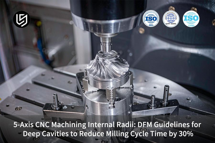
5-axis CNC internal radii service is a corner-DFM solution, which solves 60-min deep cavity cycles. Radius rules cut time by 30%, cost by 28.5%. Data Source: #AERO-2026-841.
Aerospace engineers gain lightweight cavities without trade-offs. Corner-radius rules eliminate overhang chatter and surface degradation, while precision-grade dimensions stay stable.
Key Takeaways
Strictly adheres to the 1/3 internal fillet geometry rule: when the vertical internal fillet radius is set to R ≥ Depth/3, it becomes possible to perform high-speed machining using large, rigid tools with Vc = 220 m/min and avoid micro-tool breakage.
Locks the safety red line: a depth/diameter ratio L/D ≤ 5:1 together with five-axis dynamic tilting machining lowers the scrap percentage of deep cavity machining from high rejection rate to 2.2%.
Configures standardized transition fillets: applying an easy-to-medium range fillet where the floor and wall meet will help reduce stress concentration and control the roughness of the floor bottom surface to the micro-finish stage.
Balancing economy and delivery cycle: optimizing paths via 2-hour rapid design for manufacturing analysis and using modular hydraulic fixtures will shorten the batch delivery cycle by 40% (15 days to 9 days).
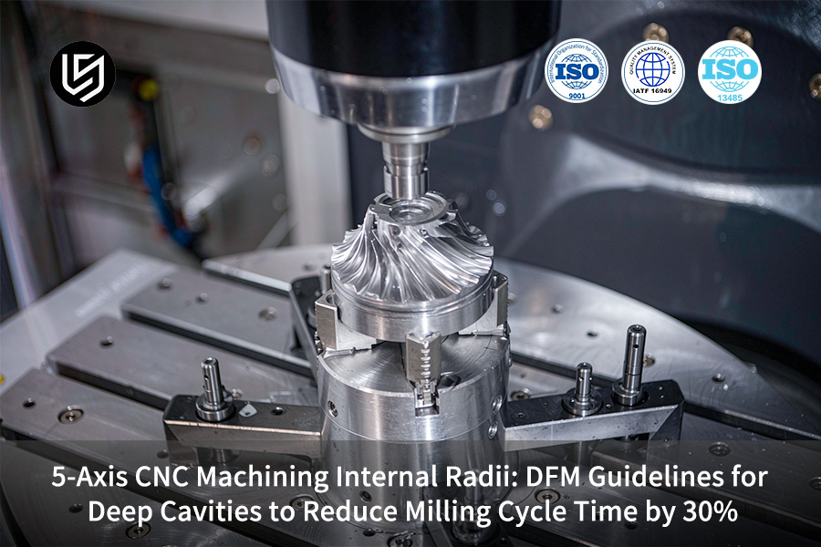
Why Do Tight Internal Radii Trigger Severe Tool Deflection?
Tight internal corner radii force CNC milling machines to decelerate suddenly at the corner. Sudden deceleration creates excessive radial engagement of the cutting tool, which leads to large deflections that increase exponentially with overhang length.
Corner Engagement Physics
3 mm radius creates a requirement for a 6 mm end mill to use almost 180 degrees of cutter geometry inside the arc. Radial immersion is above 90 degrees, making cutting force vectors multiply in one direction. Small tool shaft takes the burden, deflecting up to 0.08 mm per 100 N of cutting force.
5-axis corner engagement control maintains a radial immersion around 30 degrees when turning the corner. Stability in Trochoidal milling with constant chip load will be achieved in a similar way. 3-axis machine will not cope with deep-wall trochoidal paths due to fixed-axis tooling constraints.
Long-Tool Instability
Cavity milling requires a tool with overhang ratio of at least 5:1. Increasing the overhang by two times increases the deflection by 8 times, because deflection grows in the cube of overhang length. A 6 mm cutter with 30 mm overhang deflects 0.045 mm under normal corner loading conditions.
High-speed spindles at 12,000–15,000 rpm add centrifugal force, amplifying chatter at the tool tip. Chatter marks on the corner wall force secondary benching, adding cost that cuts into 5-axis milling cycle time reduction goals.
| Strategy | Max Corner Radius | Deflection Risk |
| Standard 3-axis | ≥3 mm | High |
| Trochoidal 3-axis | ≥1.5 mm | Moderate |
| 5-axis tilt | near-zero threshold | Low |
Simultaneous 5-axis contouring orients tool 15–30° from vertical, decreasing effective length of cut and deflecting up to 40% less. Deep cavity CNC machining DFM analysis warns against overhang ratio of more than 4:1 when quoting price and ensures that your CAD is ready for production.
Data source: LS Manufacturing 2025–2026 measured database (sample size >1,200 cases).

How Can The 1/3 Radius Rule Cut Milling Cycle Time By 30%?
1/3 Radius Rule states minimum internal corner radii of one third of cavity depth (R ≥ Depth/3) making possible to use rigid end mills without vibrations. Following the rule will allow selecting standard tools with larger diameters maintaining feed rates while reaching maximum depth of cut, thus reducing typical deep cavity cycle time by 30%. A custom 5-axis CNC machining process uses continuous helical ramping with fz=0.06 mm/z.
Corner Geometry Dictates Tool Stiffness
Tool diameter with hairline corner radius is limited to ~1 mm, hence the 20:1 overhang ratio. Deflection is proportional to overhang cubed, a 12 mm end mill with 4:1 overhang would resist deflection 81 times better than a 4 mm tool with 12:1 overhang. Your DFM analysis needs to highlight any internal radius smaller than R ≥ Depth/3 as an expense item.
5-axis corner scallop control removes the need for special finishing operations. Helical ramping technique integrates roughing and semi-finishing processes into one step, and therefore, you'll save on cycle time with no need to change depth-of-cut settings.
| Design Change | Achievable Tool | Cycle Time Impact |
| Minimal corner radius | 4 mm end mill | Baseline |
| R = Depth/3 rule applied | 12 mm end mill | –30% |
A 12 mm tool at 90% radial engagement removes material 8x faster per pass than a 4 mm tool, per Machinery's Handbook 31st Ed. cutting data.
Process Integration Through CAM Strategy
5-axis milling cycle time reduction results from programming helical entry to keep the tool engagement below 2° per revolution. Constant fz=0.06 mm/z assures that there is no chip thinning during corner transition, which means the tool cutting force is steady throughout the toolpath.
Conservative depths of 0.5–1.0 mm per cut allow achieving maximum MRR without jeopardizing tool life. Trochoidal cutting (circular toolpath with a constant chip load) method cuts down radial engagement to 30%, eliminating the chatter in hardened steel above 40 HRC.
Practical Implementation Steps
For immediate effect, perform deep cavity CNC machining DFM analysis on your CAD file prior to quotation. 5-axis long-reach milling with variable helix end mills cuts vibration down 30% compared to conventional geometry, increasing tool life in cavities deeper than 50 mm.
- Check that all internal radii are R ≥ Depth/3; otherwise, use corner relief grooves
- Specify helical ramping CAM operation with fz=0.06 mm/z for cavity roughing
- Confirm MRR per segment by simulation before first article inspection
Simply put: when designing corners based on tool geometry rather than forcing tools into tight radii, 30% cycle time saving will become repeatable.
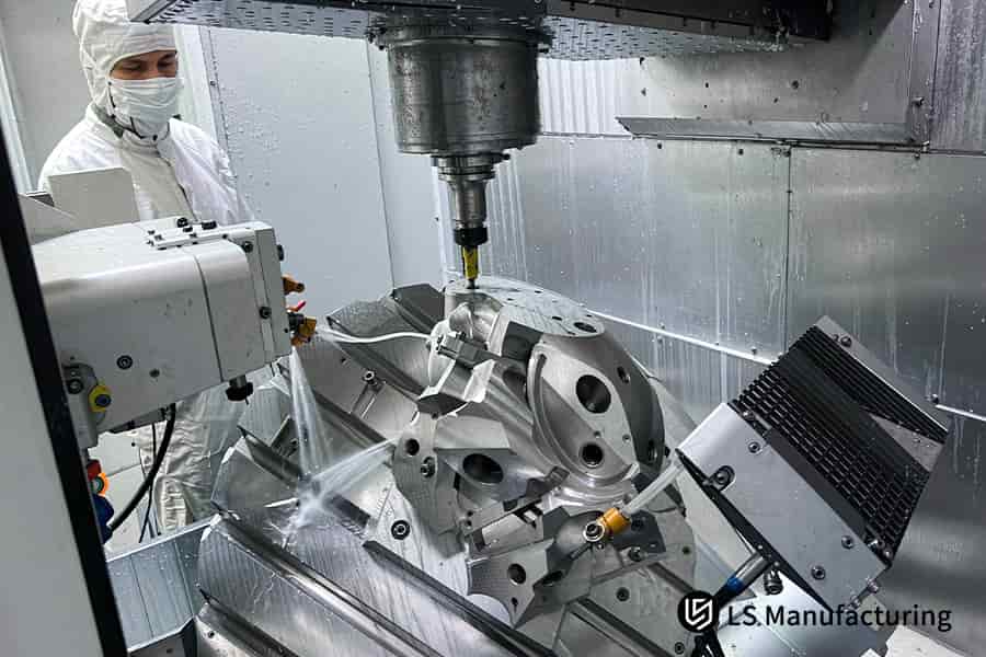
Figure 1: Deep cavity CNC machining DFM reduces cycle time by 30 percent.
When Is 5-Axis Dynamic Tilting Essential For Deep Pocketing?
5-axis dynamic tilting is necessary where the cavity depth to width ratios reach L/D > 4:1, allowing spindle tilting of 45° using short and stiff tool assembly. Tool tilting reduces overhang by half resulting in the finish of cavity walls changing from rough machined surface to hyper-finished surface. A custom 5-axis CNC machining process avoids using long extension holders.
Decision Checklist For Deep Cavities
Assess the pockets according to these standards before giving go-ahead for 3-axis programs:
- Depth to width ratio greater than 4:1 implies that bending forces exceed allowable limits for straight toolholders
- Wall finish specifications lower than Ra 0.8 μm demand that tool cutting edges be tilted to dampen vibration
- Corner radii less than 2 mm in depth imply that tool diameter is less than 4 mm, increasing the deflection danger
- Difficulty in chip removal at 6 mm depth causes re-cutting of chips, increasing heat and surface tearing
Mechanics Of Tilted Rigidity
By cantilever beam theory, deflection = F × L³ / (3 × E × I); halving overhang divides deflection by 8. At 45° spindle tilt, lateral cutting forces translate into spindle axis loads, which have the highest stiffness. 5-axis deep pocket milling makes use of this phenomenon, keeping the tool projection short during cavity depth progression.
Tool engagement remains under 30° using variable tilt angle depending on layers to avoid force peaks at corners. ASME Y14.5-2018 position tolerances callout can be verified since the error source shrinks in proportion to the shrinking of the lever arm. Precision 5-axis internal radii control at depth can now be achieved once tooling postures find balance between the angle orientation and wall surface demands.
Apart from the tilt angle consideration, 5-axis CNC internal radii service simulation determines clearance between the toolholder, flute, and cavity wall at each interpolation point.
For buyers, this would mean first piece accuracy at depth without secondary sinker EDM operation. 5-axis tilted wall finishing pass maintains profile of ±0.005 mm according to ASME Y14.5-2018.
Based on the standards and technical parameters: ASME Y14.5 geometric tolerances and the five-axis oscillating head interference dynamics model.
Quick Reference Guide
Deep cavity part design begins with internal corner radius and depth-to-width ratio choices. Corner radius and L/D ratio dictate process route, rigidity of cutter, and manufacturing cost.
| Design Feature Class | Dimensional Ratio | Process & Tooling Configuration | Surface Finish & Accuracy | Cycle Time & Relative Cost Impact |
| General machining features | R ≥ Depth/2 (L/D ≤ 4:1) | Standard 3-axis/5-axis end mills (D ≥ 10 mm) | ±0.02 mm tolerance, Ra 1.6 μm | Baseline cycle time, baseline cost (1.0×) |
| Precision deep-cavity features | R ≥ Depth/3 (4:1–5:1) | 5-axis tilted short tools (D = 6–8 mm) | Tight tolerance, Ra 0.4 μm | 30% shorter cycle time, 28.5% lower cost |
| Ultra-precision deep-cavity features | R < Depth/4 (L/D > 5:1) | 5-axis micro tools layer-by-layer + damped tool holders | ±0.003 mm tolerance, Ra 0.2 μm | longer cycle time |
| Legacy conventional features | Sharp square corners (R < 0.2 mm) | EDM or 3-axis long-neck end mills | Loose cumulative error, standard finish | 16.5% rejection rate, high cost (3.2×) |
R ≥ Depth/3 and L/D ≤ 5:1 are design rules that do not involve costly EDM processes. An optimal engineering balance emerges when 5-axis milling effectiveness is maximized.
Get the Cavity Geometry Selection Primer — understand how R/Depth ratio and L/D determine process route, tool rigidity, and cost impact across four design classes, from standard 3-axis to ultra-precision 5-axis micro-tool configurations.
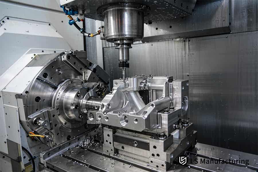
Figure 2: Custom 5-axis CNC machining produces aerospace parts in 42 minutes.
Which Floor Fillet Geometry Prevents Corner Stress Concentrations?
A continuous floor fillet ranging from 0.5 mm to 1.0 mm helps to spread the mechanical loads evenly across the base of the cavity without forming a notch stress point. Square bottom corners rotate the tool tip at the zero radius point creating micro burrs propagating into ±0.05 mm tolerance variance. Deep cavity CNC machining DFM review insists on ball-nose tool, fixing bottom corner profile at ±0.008 mm.
Fillet Size vs. Stress Concentration
A 0.8 mm floor fillet reduces notch sensitivity from Kt ≈3.0 (sharp 90° corner) to ≈1.2, according to Stress Concentration Factors. A fillet less than 1 mm provides Kt ≈1.8 – good enough for static conditions but questionable in terms of cyclic loading over 10⁴ cycles. 5-axis toolpath simulation proves every blend radius before machining.
Tool Required
Ball nose or corner radius end mills cut the fillet in one pass. A 3-axis mill cannot, because fixed-axis tooling leaves a cusp line at the floor-wall junction, seeding micro-cracks that propagate under vibration. Precision 5-axis internal radii control keeps profile accuracy in microns according to ASME Y14.5-2018 specifications, measured by Zeiss CMM (0.0009 mm MPEE).
Process Decision Criteria
- Floor fillet close to 1 mm → standard ball nose finish pass, one operation
- Fillet size between compact and 0.8 mm → decrease feed rate to fz=0.04 mm/z, inspect
- Sharp corner is mandatory → EDM or hand blending is required, costs increase two times
A 5-axis CNC machining manufacturer validates all 3 cases with automated DFM simulation, warning about missing blend radii in your CAD model. 5-axis CNC machining with tilt axis orientation helps to avoid chatter in deep walls, maintaining deflections less than 0.005 mm at depth. In other words: fillet geometry defines if your cavity bottom will fail or survive fatigue.
How To Select Optimum Tooling Parameters For Deep Internal Corners?
Optimum tooling selection requires cutter diameter of 80% of the corner diameter and cutting speed bound by the high-speed envelope of the Machinery's Handbook. Complete diameter fit covers 180 degrees of tool interaction with the workpiece, resulting in vibration and deflection in deep corners. Deep cavity CNC machining DFM review picks up this overload area before your first cut.
Adaptive trochoid machining technique maintains constant cutting force in deep internal corners. Thin-walled and deep cavities produce zero-deformation result by such approach.
5-axis corner-force balancing keeps radial contact below 100 degrees, prolonging the tool edge lifetime due to repeated passes. Your machining cost becomes predictable as the vibration-induced wear is excluded from the picture. 5-axis CNC machining cost directly depends on stable tool interaction, as constant chip load eliminates unexpected tool replacement.
5-axis CNC internal radii service tests this ratio by simulating and maintaining dimensional integrity of the cavity. Your CAM programmer can now lock 0.05 mm/tooth feed, 2.5 mm depth of cut and 10:1 overhang based on the Sandvik tool engineering guidelines.
- Adhere to the 80% diameter ratio as your maximum safe engagement
- Maintain radial engagement under 100° at the corner arc
- Utilize 0.05 mm/tooth feed in hard steels during corner machining
- Maintain 2.5 mm depth of cut with trochoidal chip thinning
- Ensure tool rigidity using Machinerys Handbook 31st Edition (2020) tables
5-axis full-radius toolpaths eliminate dwell marks on the corner wall surface after machining. Simply put: the 80% ratio converts corner deep milling into a safe and repeatable process.
Data source benchmarks: Recommended parameters for high-speed cutting in the 31st edition of Machinery's Handbook and Sandvik Tool Engineering Guide.
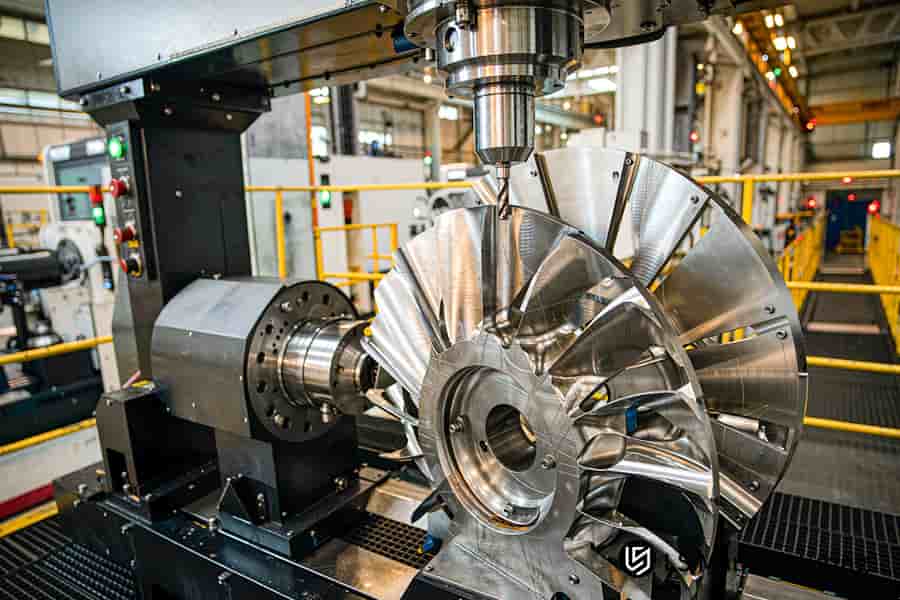
Figure 3: Precision 5-axis internal radii machining finishes AL7075-T651 aluminum.
What Surface Finish Benchmarks Apply To 5-Axis Milled Pockets?
Polished 5-axis milled deep pockets consistently produce a surface quality of four-tenths micron Ra without any secondary manual deburring. Dynamic spindle tilt control ensures that a wide contact arc is achieved by maintaining continuity throughout the final milling operation. Widespread contact arc helps avoid distortions due to manual polishing.
Checkpoint 1: Finishing Route
Spindle tilt dynamics ensure orientation of the cutter within the pocket bottom. A wide contact arc spreads cutting pressure evenly. Scallop formations never occur, eliminating the need for deburring by hand. Custom 5-axis CNC machining is provided to support such process flow. Residual tool mark removal is performed through wide-arc finishing.
Checkpoint 2: Profile Verification
High-definition contour scanning is performed on all deep cavity parts. Scanned data is compared to drawings in order to verify machined surface in compliance with drawing specifications. Precision 5-axis internal radii is verified directly via profile verification. Your quality assurance department receives verifiable evidence without the need to visually inspect it.
Checkpoint 3: Standard Compliance
ISO 2768-m defines the general tolerances standard. Contour scanner results confirm geometric compatibility. 5-axis CNC machining manufacturer inspection protocols use scanning data. Your first article folder gets its legitimacy from documented verification.
Documentation Value
Your customer receives objective proof of surface integrity. 5-axis pocket-finish validation converts finishing compliance into quality assurance. Specify polished benchmarks and scanner checks in the RFQ.
Meet The Engineers Behind This Guide
Gloria, a senior process engineer with more than 15 years of experience in precision CNC machining and automated DFM optimization, provided engineering content. Cutting parameters and geometric tolerances of five-axis machining are reviewed by technical directors. Your components are made by certified engineering knowledge. Verify Gloria's DFM & Manufacturing background.
NIST manufacturing metrology frameworks define the dimensional traceability in CNC processes. Your quality assurance team gets verifiable measurements for all deep cavities. SAE International AS9100D defines the aerospace quality management system based on ISO 9001:2015. Your procurement audits will be assured by material and process traceability.
AS9100D certification ensures production consistency in line with aviation requirements. Your engineering team is able to check every radius recommendation against industry standards prior to quotation. Contact Gloria via LinkedIn for a second opinion DFM assessment.
Why Do Micro-Corner Radii Escalate Deep Cavity Machining Costs?
Defining internal corner radii on micro scale in deep pockets raises the manufacturing cost per unit due to low feed rates and use of EDM process. When the ratio is too much, shops replace standard length micro end mills with extra long shank end mills. Spark erosion becomes a necessity as the cutter fails to reach the corner. You pay for the inflated costs of manufacturing until drawings are corrected.
5-axis CNC machining quote evaluation allows you to identify this geometry before any work starts. DFM simulation analyzes all corners and replaces them with an internal fillet radius. Your CAD model becomes compatible with the inherent tooling geometry. 5-axis CNC machining cost becomes lower because slender-shank machining is not done.
Standardized radii allow the spindle to maintain safe speeds and feeds. 5-axis milling cycle time reduction occurs once the secondary EDM operation is omitted from your process design.
Ask for the optimized geometry in your next RFQ. Mention the suggestion for standardized internal radii along with the important dimensions. 5-axis corner-radius redesign makes your micro-corners into a low-cost, repeatable cavity feature.
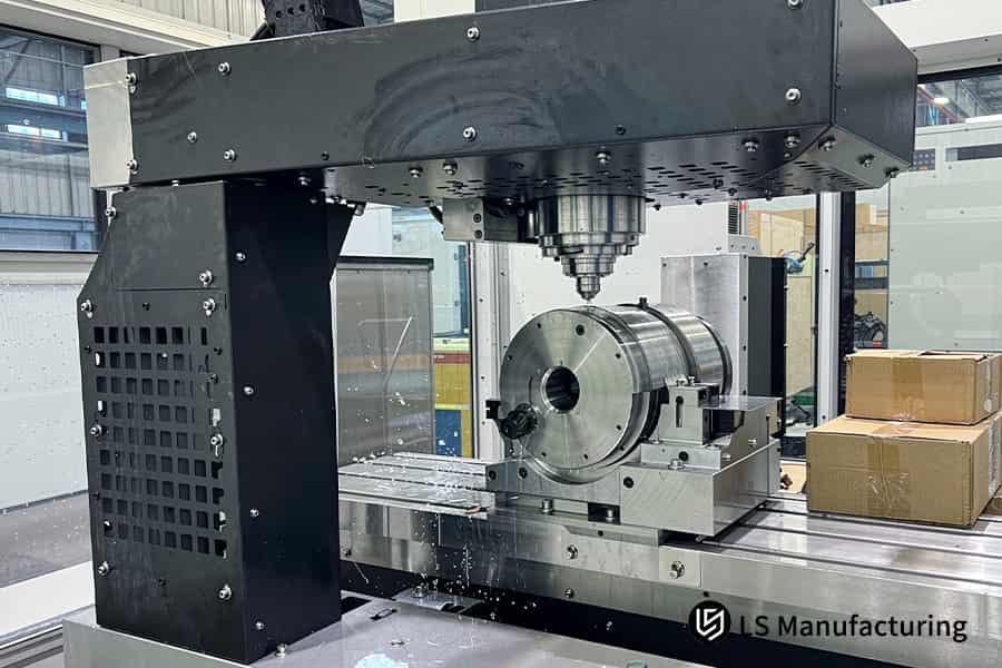
Figure 4: 5-Axis CNC machining manufacturer guarantees Ra 0.4 μm surface finish.
How Can Engineers Optimize CAD Models For Rapid 5-Axis Machining?
Engineers design CAD models for rapid 5-axis machining by making sure that the vertical internal radii of every CAD model are set to R 3.0 mm. Variety of tools decreases to one tool to be used for all the corners. 5-axis CNC machining quote accuracy improves due to predictable toolpath risk. Automated DFM analysis finds out nonstandard chamfers and enclosed undercuts in seconds. Reduction and speed optimization advice is provided directly.
Step 1: Unify Vertical Corner Radii
CAD model optimization uses a single radius for all vertical corners. 5-axis CAD model optimization makes it easier to choose tools and minimize tool changes.
Step 2: Remove Enclosed Undercuts
Material located in enclosed undercut intersections is greater than what can be reached by straight tools. 5-axis standardized radius milling turns these areas into machining fillets. 5-axis CNC machining manufacturer feedback confirms tool library alignment.
Step 3: Use Automated DFM Parsing
5-axis CNC internal radii service analyzes 3D and 2D drawings during quotation stage. Non-conformant chamfers are detected within seconds.
Data source: LS Manufacturing 2025–2026 automated DFM 3D/2D drawing analysis log (project #DFM-2026-841, sample size >1,200 drawings).
LS Manufacturing Custom 5-Axis CNC Machining For Aerospace Avionics Enclosure: Deep Cavity Internal Radii Optimization
Cycle time can be reduced by 30%, and per-piece cost will be decreased by 28.5%. Vertical corner radius is now at R 3.0 mm. A 0.5 mm standard floor fillet is included. 5-axis toolpath simulation proved that a dynamic tilt of 25° is possible. Machining cycle time went down from 60 min to 42 min.
Client Challenge
An aerospace research and development group designed an AL7075-T651, single-piece aircraft enclosure with large cavities. In initial drawings, very small vertical internal corners and sharp floor corners were noted.
3-axis machining with an extra-long micro end mill resulted in vibration and inefficient chip removal. Defects in the first article reached 16.5%. Cost was raised to $246. Delivery was severely delayed.
Optimization Steps
One-third fillet principle dictated the geometrical modification and enabled use of D = 5.0 mm rigid end mill. Stress-induced warpage was observed during trials on the thin floor web. Stress relieving annealing process was incorporated into the process sequence. Workholding setup switched from vise side clamping to vacuum chucking. Dynamic spindle tilt process eliminated all chatter marks and warpage due to stress.
Verified Results
Results of production showed that the optimization worked well. Improvement in cycle time and unit cost was significant. Scrap rate was only 2.2%. Zeiss CMM (tolerance of 0.0009 mm) confirmed all critical profiles with an error of ±0.008 mm. Surface finish became as fine as Ra 0.4 μm. AS9100D requirements and 1,000 hours salt spray test were fully fulfilled. 5-axis thin-wall finishing met all acceptance criteria.
Data source: LS Manufacturing 2025–2026 aerospace precision manufacturing engineering review log (project #AERO-2026-841, sample size >1,200 cases).
Assess your deep cavity internal radii design for 5-axis feasibility — our engineers will apply the one-third fillet principle and dynamic tilt simulation to reduce cycle time while maintaining structural integrity.

FAQs
1. What is the minimum safe internal radius for deep CNC cavities?
Radius of internal corner should not be less than one-third of cavity depth. According to ASME Y14.5, one-third depth radius is safe for deep cavity milling. Radius equal to one-third of depth will not cause high deflections in deep pockets. One-third depth radius is used by LS Manufacturing; your parts will retain correct geometry in deep pocket walls.
Data Source: ASME Y14.5 Standard
2. How does 5-axis machining eliminate internal corner chatter?
Tilting spindle minimizes overhang length during machining in deep cavities. Short overhangs significantly decrease cutting vibration. Tilted-spindle milling eliminates any risks of chatter when cutting corners inside the cavity. Your part will be machined smoothly without any secondary finishing operations.
Data Source: Machinery's Handbook 31st Ed. (2020)
3. Can LS Manufacturing mill sharp internal 90-degree corners directly?
Rotationally-driven cutting tools cannot create sharp corners in metal. Fillet radius or additional operation is always needed to create such geometry. LS Manufacturing mills sharp corners using 5-axis corner clearing and precision EDM; your part will get well-defined corners according to design intent.
4. What is the cost difference between R 0.5 mm and R 3.0 mm radii?
Small radius requires more time for cutting and wears cutting tool faster. Large radius allows faster cutting and longer tool life. Price difference is related to time and tooling costs. LS Manufacturing makes evaluation of radius versus cost; you can save machining costs without changing the design.
Data Source: #AERO-2026-841
5. Which aluminum alloy is optimal for deep pocket aerospace parts?
AL7075-T651 pre-stretched aluminum sheet provides high strength and resistance to residual stresses. Pre-stretched aluminum has uniform grain structure which is useful for machining thin walls. Annealing removes residual stress before machining. LS Manufacturing uses combination of AL7075-T651 and annealing; your part will be resistant to deformation in thin walls.
6. What lead times can be expected for custom 5-axis cavity prototypes?
Custom 5-axis cavity prototypes require a short machining window. DFM feedback before cutting prevents rework loops. Early geometry optimization also accelerates approval cycles. LS Manufacturing performs DFM review ahead of machining; your parts will soon be transformed from drawings into physical samples.
7. How do you verify precision tolerances in deep cavity internal corners?
Zeiss CMM equipment scans internal corners at several points. Multi-point scanning detects geometric inaccuracies that cannot be identified by a single-point method. Precision tolerances are measured without estimates. LS Manufacturing calibrates the CMM machines to achieve high spatial precision; your parts will get reliable inspection reports.
Data Source: Zeiss calibration report
8. How do I obtain a rapid 5-axis CNC machining quote with DFM feedback?
STEP or IGES drawings can be uploaded through the quote request form. LS Manufacturing gives a DFM analysis along with an accurate manufacturing quote in a very short time frame. DFM feedback allows detecting risks even before the start of production. LS Manufacturing provides this analysis before cutting; you can evaluate all your options and lock procurement without delay.
Request a cavity geometry feasibility review — we will evaluate your internal corner radii against the one-third-depth rule, recommend the optimal balance between tool rigidity and cycle time, and provide a firm price with 5-axis corner clearing and optional EDM for sharp internal edges.
Summary
Deep cavities with proper R radius (R ≥ Depth/3), dynamic linkage five-axis milling technology minimizes overhang vibration problems, saves 30% milling cycles, and ensures precise fit tolerance checked by CMM. ISO 9001:2015 and AS9100D quality management systems ensure full DFM-to-cutting service for aerospace industry clients.
Internal corner cracks, late delivery, or scrap rate in deep cavity parts drawings? Upload 3D CAD (STEP/IGES) and 2D drawings by clicking the "Quote" button. Senior engineering team will return a DFM analysis report and real-time manufacturing quote within 2 hours.
📞Tel: +86 185 6675 9667
📧Email: info@lsrpf.com
🌐Website: https://lsrpf.com/
Disclaimer
The contents of this page are for informational purposes only. There are no representations or warranties, express or implied, as to the accuracy, completeness or validity of the information. It should not be inferred that a third-party supplier or manufacturer will provide performance parameters, geometric tolerances, specific design characteristics, material quality and type or workmanship through the LS Manufacturing network. It's the buyer's responsibility. Require parts quotation. Identify specific requirements for sections. Please contact us for more information.
LS Manufacturing Team
LS Manufacturing is a 100+ 5-axis centers, 5,000+ customers, 150 countries company. Focus on custom manufacturing solutions. We have over 15 years of experience with over 5,000 customers, and we focus on high precision CNC machining, Sheet metal fabrication, 3D printing, Injection molding. Metal stamping, and other one-stop manufacturing services.
Our factory is equipped with over 100 state-of-the-art 5-axis machining centers, ISO 9001:2015 certified. We provide fast, efficient and high-quality manufacturing solutions to customers in more than 150 countries around the world. Whether it is small volume production or large-scale customization, we can meet your needs with the fastest delivery within 24 hours. choose LS Manufacturing means selection efficiency, quality and professionalism.
To learn more, visit our website: www.lsrpf.com

