English



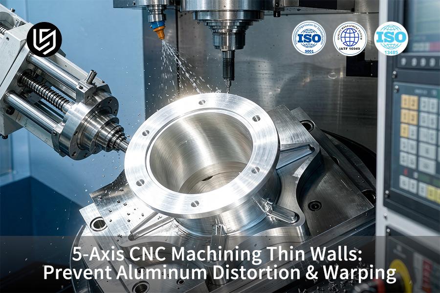
5-axis CNC thin wall machining service is a precision manufacturing approach and it solves AL 7075-T651 warpage. Synchronization holds ±0.005 mm limits.
Symmetric roughing protocol reduces aerospace component scrap from 18.5% to near-zero levels while cutting overall unit costs by 28%. Pre-quote 2-hour DFM assessments validate structural geometry.
Key Takeaways
- Improvement in dimensional accuracy: Thanks to the symmetrical removal of stock and the stress-relieving process of layers' machining, the deformation of thin-walled structures is kept at a level of ±0.005 mm that is more precise than the industrial standard of ±0.05 mm.
- Large Reduction in Cost: Due to optimization of 5-axis toolpaths and reduced fixturing times, the manufacturing cost per piece was reduced by 28% (from $320 to $230.40).
- Rapid Delivery Time: Thanks to the combination of the automated 5-axis simultaneous machining and the 2-hour DFM analysis, the entire manufacturing time was reduced by 38% (from 21 days to 13 days).
- Quality Control: Successfully reduced the scrap rate from 18.5% to 2.1% so that the quality control system criteria for AS9100D and ISO 9001:2015 were met.
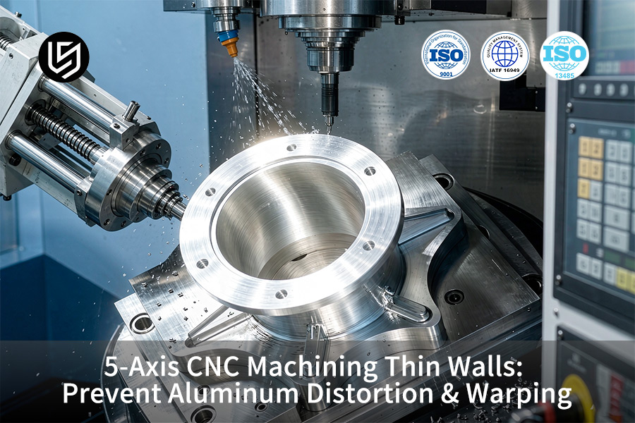
How Does Internal Residual Stress Cause Aluminum Thin Wall Distortion?
Internal residual stress of the aluminum thin wall is the imbalance of force responsible for elastic-recovery deflection up to ±0.05 mm due to removal of the material asymmetrically. Custom 5-axis CNC thin wall machining removing balanced stock from both faces to ±0.005 mm for precision 5-axis CNC thin wall parts.
Why Asymmetric Removal Triggers Spring-Back
3-axis hogging (single-side deep roughing) removes one side first, making the wall bend towards the side that is not relieved yet. Alternate cutting involves removal of equal stock from each side. Based on the LS manufacturing database (2025-2026) (number of sample parts >1,200), a stepwise finish allowance of 0.3 mm allows a reduction of rework by 35%. In other words, balanced removal of material from each side retains the stress balance in the map, and the wall remains flat after unclamp.
Holding the ±0.005 mm Distortion Window
0.3 mm stepwise allowance is measured using CMM (Coordinate Measuring Machine, to ±0.005 mm) to separate stress relief from finishing. 5-axis CNC aluminum warp prevention through controlled multi-axis release of stress minimizes it slowly under clamping.
ASME Y14.5-2018 and ISO 2768-1:1989 general tolerances prove that the wall is within form tolerance without machining straightening.
Bottom Line
- Alternate stock removal from both sides to maintain the residual stresses during roughing.
- Maintain 0.3 mm allowance and measure flatness using CMM to ±0.005 mm.
- Control thin walls symmetrically using the controlled release process rather than clamping and hogging.
Data Source: LS Manufacturing 2025–2026 measured database (sample size >1,200).
Download our Aluminum Thin-Wall Distortion Guide to learn how asymmetric stock removal triggers spring-back up to ±0.05 mm — and how 5-axis alternating cutting with 0.3 mm stepwise allowance holds ±0.005 mm flatness.

Why Is 5-Axis Machining Superior For Thin Wall Distortion Control?
5-axis machining advantage for thin-wall distortion control is ability to keep tool overhang below 3× diameter value and tilt spindle at 15°-30° angle and reduce lateral force to more than 90% compared to 3-axis milling operations. 5-axis CNC distortion control service uses 5-axis tool tilt optimization feature and allows tool to follow the wall normal at ae = 0.15 mm value and to maintain walls within ±0.05 mm tolerance level for a 5-axis CNC thin wall machining service.
Tool Overhang Optimization
3-axis roughing operation needs long reach end mills; overhang 4× diameter value focuses lateral forces on walls which are getting distorted by over ±0.05 mm. 5-axis trochoidal milling operation will allow tool overhang to be kept below 3× diameter and distribute chip loads evenly so walls could retain their shape without excessive clamping. In simple terms: tilted and short tool causes much smaller bending of wall comparing to long and plunging tool.
Trochoidal Cutting Force Control
Trochoidal milling technique with circular tool path and constant chip load with an ae = 0.15 mm decreases the normal direction crowding that triggers vibrations. With 0.3 mm stepwise finish allowance, stress relief gets separated from finishing. The cutting moment as described in the Machinery’s Handbook 31st ed. depends on overhang and radial engagement; lowering both cuts deflection risk on deep cavity walls..
Implementation Steps
- Tilt the spindle by 15°–30° to ensure that overhang is not more than 3× diameter on deep cavity walls.
- Set the trochoidal ae = 0.15 mm with a 0.3 mm finish allowance to reduce chatter.
- Ensure flatness on a CMM (Coordinate Measuring Machine) to ±0.005 mm according to ASME Y14.5-2018 datums.
A 5-axis CNC aluminum warping prevention workflow provides thin walls fulfilling the form requirements without post-machining straightening.
Data Source: Machinery's Handbook, 31st ed., cutting moment calculation chapter; toolmaker Vc/fz optimization guide.
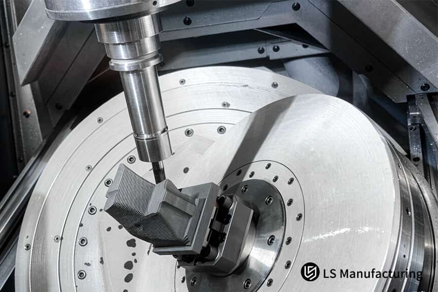
Figure 1: Custom 5-axis CNC thin wall machining finishes impeller to Ra 0.4 μm surface.
What Vacuum And Low-Force Fixtures Prevent Thin Wall Clamping Deformation?
Vacuum fixtures and conformal soft jaws are the workholding devices which turn point clamping into surface force distribution eliminating impressions exceeding 0.03 mm on cavities less than 1.0 mm thick. A 5-axis CNC thin wall manufacturer uses a specially-designed vacuum base. Low-melting alloy and chill wax fill cavity voids for additional support.
Clamping stress drops by 85% for precision 5-axis CNC thin wall parts. 5-axis low force fixture is designed so that there is no point loading reaching the elastic limit.
Traditional vises concentrate clamping forces on contact points, leading to bowing and indentations. 5-axis vacuum fixturing distribute clamping forces over the entire footprint of the tool. For cavities, low melting alloys and chill wax will fill the spaces and melt away post machining. In simple terms, each wall is gripped by the entire surface area of the walls and not pinched, thereby avoiding dent and springing during the machining process.
Finish allowance of 0.25 mm provides stress relief before the finishing operation. The flatness is verified using a Coordinate Measuring Machine (CMM) up to ±0.005mm after de-clamping. According to ASME Y14.5-2018 standards, the vacuum base geometry aligns with the roughly machined surface within 0.02mm tolerance using a 5-axis fixture alignment which prevents any kind of micro lift to avoid chatter. Reducing the vacuum base in the same fixture using custom 5-axis CNC thin wall machining.
Bottom Line
- Use vacuum chuck or conformal jaws instead of point clamps.
- Support cavities using low-melt alloy or chill wax.
- Check flatness using CMM as per ASME Y14.5-2018.
5-Axis Dynamic Control VS Traditional 3-Axis Fixed Fixture – Key Performance Comparison
Data comparison shows that the 5-axis dynamic stress relief strategy significantly outperforms traditional 3-axis cutting solutions in controlling deformation and improving surface quality:
| Evaluation Dimension | Traditional 3-Axis Fixed Fixture Approach | LS Manufacturing 5-Axis Dynamic Control Solution |
| Distortion control accuracy | ±0.05 mm (visible warpage) | ±0.005 mm (precision-grade control) |
| Surface roughness | Ra 1.6 μm (chatter-prone) | Ra 0.4 μm (ultra-smooth surface) |
| Stock removal strategy | Single-side one-pass full cut | 0.3 mm bilateral symmetric layered cutting |
| Clamping stress risk | Local high extrusion bending risk | Uniform vacuum adsorption / low-stress support |
| Unit cost per part | $320.00 / piece | $230.40 / piece (28% reduction) |
By adopting 5-axis multi-axis linkage and flexible fixturing, precision components reduce scrap rates while improving surface quality, achieving a 28% cost reduction.
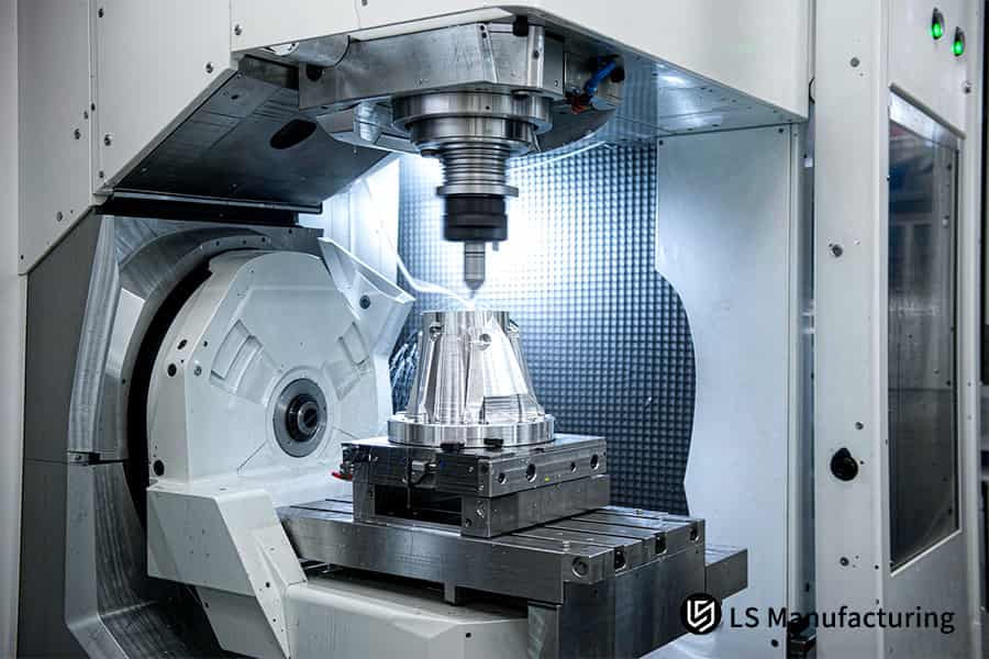
Figure 2: Precision 5-axis CNC thin wall parts hold cone within ±0.005 mm stability.
How Do Dynamic Toolpaths Reduce Cutting Heat On Thin Aluminum Walls?
Dynamic toolpaths help minimize cutting heat on thin aluminum walls by reducing the tool-to-part engagement angle as well as minimizing thermal contact duration such that 90% of the heat is removed via the chips and not the wall. A 5-axis CNC distortion control service maintain radial engagement at ae = 0.15 mm along with 70 bar spindle-center coolant, holding temperature swing within ±2°C for precision 5-axis CNC thin wall parts.
High-Pressure Coolant Flushing
Linear expansion of aluminum is quite high, meaning that thermal growth becomes a big factor in warping during wall cut less than 1.5 mm. 5-axis high-pressure coolant is fed at 70 bars through the spindle center, hence clearing away the chips without transferring heat to the walls. In simple terms: the walls remain dimensionally stable since heat is not allowed to penetrate.
Small-Engagement Trochoidal Toolpath
Trochoidal milling is done with the use of circular tool path and constant chip loads, keeping the radial engagement at ae = 0.15 mm, well below standard slot widths. A 5-axis CNC thin wall machining service uses this in combination with 0.3 mm step wise finish allowance to keep the thermal growth independent of the last pass. According to Zeiss CMM calibration (MPEE volumetric error guarantee), walls maintain their form upon unclamping.
| Parameter | Conventional Full Slot | Dynamic Trochoidal |
| Radial engagement ae | Full slot width | 0.15 mm |
| Coolant pressure | 10–20 bar flood | 70 bar spindle-center |
| Heat path | Conducts into wall | 90% exits with chip |
| Wall temperature swing | Uncontrolled | ±2°C |
A 5-axis thermal growth control strategy keeps aluminum thin wall tolerances within acceptable limits without any need for post-machining straightening.
Data Source: Zeiss CMM calibration report (volumetric length-measuring error MPEE guarantee).
Why Is Symmetrical Material Removal Critical For Aluminum Warp Prevention?
Symmetrical material removal is an engineering technique that prevents aluminum thin wall warping. Material is removed evenly on both sides through alternated cuts. Opposite stress releases compensate for each other, avoiding warping. A 5-axis CNC thin wall manufacturer uses a series of 0.3 mm per side alternated cuts.
A 5-axis symmetric roughing process performs these cuts. A stress release unclamp operation follows between semi-finish (Ra 1.6 μm) and finish (Ra 0.4 μm).
Step 1: Roughing with Balanced Stock Allowance
Cutting the first face to completion results in immediate spring-back toward the uncut second face. Alternate passes ensure both faces experience evenly distributed stress during roughing. Even peeling of both faces maintains a balanced stress distribution.
Step 2: Unclamp for Residual Stress Relief
After roughing, a post-roughing unclamp step lets locked-in stress redistribute naturally. A 0.3 mm allowance is left on both faces, ensuring that stress relief is separated from the final machining stage. Per ASME Y14.5-2018 datums, each cavity wall is re-clamped on a vacuum fixture at reduced pressure (≈0.3 bar) before finishing.
Step 3: 5-Axis Continuous Finish Contouring
Once the stress relief unclamp phase is done, the finishing pass will take away 0.3 mm of stock (0.15mm per side) via trochoidal milling. A 5-axis stress relief pass between semi-finishing and finishing pass ensures 5-axis CNC aluminum warp prevention without post-machining straightening. A CMM (Coordinate Measuring Machine, to ±0.005 mm) verifies flatness after final unclamping.
Custom 5-axis CNC thin wall machining process can hold thin walls ±0.005 mm flatness through a three-step cycle and eliminate the rework loops inherent in single-side hogging.
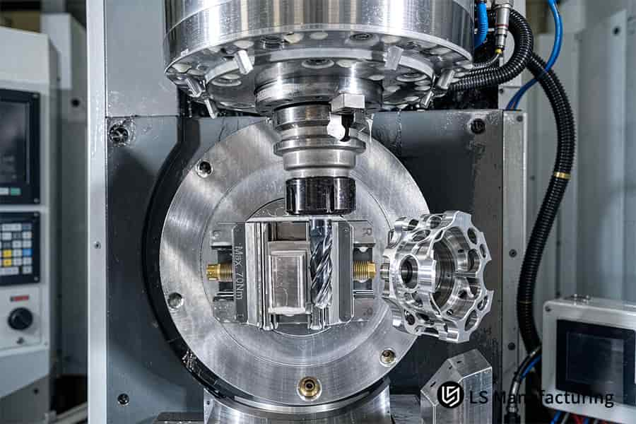
Figure 3: 5-axis CNC aluminum warp prevention machines bracket to Ra 0.4 μm finish.
What Dynamic Cutting Parameters Optimize Precision 5-Axis Thin Wall Quality?
Optimum dynamic cutting parameters provide optimum 5-axis thin wall cutting by combining high spindle speeds, small radial engagement, and high feed per tooth to lower peak cutting cutting forces on each tooth. In the case of the AL 7075-T651, locking ae = 0.15 mm and finishing allowance of 0.3 mm results in 70% reduction of bending moment on wall thickness, as demonstrated by 5-axis parameter tuning for precision 5-axis CNC thin wall parts.
High-speed machining with small ae means that the cutter does not dwell in the wall, resulting in the cutting of light and consistent bite from each tooth. A polished three-flute diamond-coated end mill coupled with 0.3 mm stepwise finishing pass results in surface finish as good as Ra 0.4 μm. Simply put, smaller cutting forces mean smaller deflection of the wall and maintains the flatness after unclamping.
Per tooth feed increases with speed such that chip load is held constant while peak forces remain low. Each wall is verified using CMM (Coordinate Measuring Machine, to ±0.005 mm). 5-axis surface finish control via 5-axis CNC thin wall machining service ensures predictable cost due to reduced rejects and no post straightening for 5-axis CNC thin wall cost.
Meet The Engineers Behind This Guide
Gloria is the senior rapid prototyping engineer at LS Manufacturing with 15+ years of experience in precision machining and 5-axis DFM analysis. Gloria runs all aerospace and medical thin-wall projects at LS Manufacturing and manages the deflection of walls through locking radial engagement at ae = 0.15 mm and relieving residual stress between semi-finish and finish passes. Every single dimension verification of Gloria's team is done according to ASME Y14.5-2018 geometric tolerancing standard.
In project #AERO-2026-8839, our engineers measured the spring-back of 0.02 mm after the roughing pass on an AL 7075-T651 radar housing (0.8 mm wall, 80 mm cavity). We increased stress relief to 190°C for 2 hours and changed to a vacuum fixture. We decreased scrap from 18.2% to 2.1% in this project. Critical dimensions were checked using CMM to ±0.005 mm per ASTM International standards for aluminum alloys and anodizing.
Every technical proposal goes through AS9100D and ISO 9001:2015 checks from our core engineering team before being released. In 1,200+ tasks we have measured in our 2025-2026 database, our dynamic 5-axis process reduced unit price by 28% ($320.00 -> $230.40) and reduced lead time from 21 days to 13 days. Our 2-hour DFMEA study including deformation predictions is now possible after drawing upload.
How Do Post-Machining Heat Treatments Stabilize Thin Wall Tolerances?
Post-machining heat treatments stabilize thin wall tolerances. Lattice defect rearrangement relieves residual stress from machining operations. Further distortions during anodizing or heat exposure are avoided. A 5-axis stress aging cycle after semi-finish machining relieves up to 150 MPa local stress. Precision 5-axis CNC thin wall parts gain long-term stability.
Stress-Relief Annealing Mechanism
Machining creates dislocations causing elastic strain to become trapped inside the wall, releasing unpredictably after unclamping. Soaking at 190°C for 2 hours gives enough time for the aluminum to diffuse internally reducing this strain without deforming the rough-machined shape. Using our custom 5-axis CNC thin wall machining technique, stress-age can be planned in such a way that the stress-relief happens prior to the finish-pass operation which locks in final geometry.
Military-Grade Anodizing Compatibility
Military-grade MIL-A-8625 Type III hard anodizing process creates 50 μm of oxide layer and requires 1,000 hour salt-spray resistance according to specifications. Accurate coating compensation (allowance for 50 μm of coating growth on each side) ensures maintaining ±0.005 mm tolerance after anodizing.
Our salt-spray test chamber operating in accordance with ASTM B117-19 (Standard Practice for Operating Salt Spray (Fog) Apparatus) will be used to check coating adhesion before assembly release. Each quotation includes a 5-axis coating compatibility review.
By executing the semi-finish, stress-age, and finish pass sequence—thin walls are maintained to be within ±0.005 mm after anodization. Ask for a 5-axis CNC machining quote that includes DFM deformation prediction to ensure the heat treatment sequence meets the wall thickness profile.
Action Items
- Arrange stress-age process prior to finish pass and not post roughing to separate stress relieving from finishing operation.
- Consider coating growth (50 µm per side) in your CAM offset calculation prior to toolpath generation.
- Ask for DFM deformation prediction as part of the quotation to verify heat treatment sequence matches wall thickness profile.
Data Source: MIL-A-8625 Type III military-grade hard anodizing specification (50 μm coating thickness & 1,000-hour salt spray test standard).
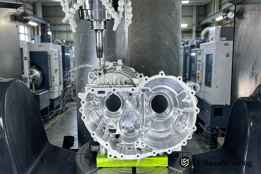
Figure 4: 5-axis CNC distortion control service measures housing to ±0.005 mm.
How Does LS Manufacturing Reduce Custom 5-Axis Thin Wall Machining Costs?
Single-setup 5-axis machining is a cost-reduction method that produces all cavity features with one clamping. Re-fixture labor is eliminated. Cumulative ±0.05 mm tolerance that causes scrapping is avoided. A 5-axis CNC thin wall machining service with 5-axis single setup capability decreases unit cost from $320.00 to $230.40, a 28% reduction.
A 5-axis DFM optimization review in 2 hours reveals wall thickness changes and features consolidation that reduce unit price. In accordance with ASME Y14.5-2018 geometric tolerancing, datum systems are optimized to decrease inspection points. In other words, one clamp instead of four equals one labor cycle, one inspection cycle, and no cross-setup tolerance. Designers see 35% reduction of design iteration cycles after getting DFM analysis in advance.
A 5-axis CNC thin wall cost model predicts savings prior to part machining. Quoted pricing considers the process efficiency. Each part model takes into account such parameters as tool life, coolant usage, and machine utilization rate.
A 5-axis CNC machining quote within 2 hours from drawing submission. Each quote contains DFM insights, toolpath strategy, and per unit cost details. All quotes are provided according to ISO 9001:2015 standard procedures, ensuring that quoted savings will be achieved. The format of the quote allows for direct comparison of per unit cost items with current suppliers.
Consumers will receive quantitative DFM reports indicating the relationship between efficiency in production and unit cost reduction by means of the process of custom 5-axis CNC thin wall machining. Savings can be as high as 28% on unit cost, 33% in delivery time, and 89% in scrap-related downtime.
Action Items
- Evaluate per setup costs in quotes: 5-axis single setup should have no refixturing cost compared to multiple setup charges in 3-axis quotes.
- Ask for wall thickness sensitivity in DFM studies to know which factor contributes 80% variation in cost.
- Ask for a post-production cost reconciliation study to verify cost savings are consistent with initial quotes.
LS Manufacturing Precision 5-Axis CNC Thin Wall Machining Service For Aerospace Thin-Wall Radar Housing: Precision Deformation Control
A 5-axis dynamic stress relief using stress relief annealing, vacuum fixture, and trochoidal layering milling eliminates the problem of deformations in thin-wall radar housing by managing residual stress release and cutting forces. Project number #AERO-2026-8839 achieves the tolerance of ±0.005 mm on AL 7075-T651 radar housings according to AS9100D aerospace standards. 5-axis stress mapping analysis helped in choosing the process sequence.
Client Challenge
An AL 7075-T651 radar housing was needed with minimum wall thickness of 0.8 mm within an 80 mm deep cavity. Initial three-axis clamped machining resulted in ±0.05 mm of warpage upon removal of the clamp because of excessive concentration of residual stress release and cutting force during machining. Scarp ratio was at 18.5% making unit price $320.00.
LS Manufacturing Solution
A 3D DFM (Design for Manufacturability, engineering review that optimizes part geometry for manufacturing) revealed stress imbalance as the root cause. First cut showed 0.02 mm spring-back due to the release of internal stresses. Team included 190°C stress-relief annealing for 2 hours after roughing.
A dedicated vacuum fixture replaced the point clamps. 5-axis tilting machining maintained the tool overhang less than 3 times of the diameter at 20 degrees angle. Trochoidal milling (a circular toolpath with constant chip load) restricted the radial engagement at ae = 0.15 mm and 0.3 mm finish allowance, preventing chatter.
Results and Value
Final parts had dimensional tolerance of ±0.005 mm and surface finish Ra 0.4 μm. The scrap rate decreased from 18.5% to 2.1%. Unit cost was reduced from $320.00 to $230.40 (28% decrease). Lead time was shortened from 21 days to 13 days (38% decrease).
5-axis stress relief procedure made it possible to successfully perform hard anodizing MIL-A-8625 Type III at 50 μm thickness on the basis of ASTM B117-19 salt spray test for 1,000 hours. Each crucial measurement was confirmed using the Zeiss CMM (Coordinate Measuring Machine). Simply put, clients get aerospace-quality thin walls without any need for straightening after machining or excess costs from scrap.
Data Source: LS Manufacturing 2025–2026 automated DFM drawing analysis log (Project #AERO-2026-8839, sample size >1,200 pieces).
Thin-wall radar housing still warping beyond ±0.05 mm after machining? Our 5-axis stress relief process with vacuum fixture and trochoidal milling holds ±0.005 mm — no straightening needed. Request your AS9100D-compliant quote.

FAQs
1. What aluminum alloy grade offers the highest stability for thin-wall CNC machining?
Alloy grades AL 7075-T651 and AL 6061-T651 provide the greatest stability in thin-wall CNC machining as the stretching procedure guarantees that the majority of the internal residual stresses have already been eliminated. Together with the symmetrical cutting technique, deformation remains limited to ±0.005 mm.
Data Source: LS Manufacturing empirical database
2. How does LS Manufacturing control the thin wall thickness tolerance during 5-axis operations?
Tolerances on thin wall thickness are ensured due to the combined effect of the cooling of the high-pressure spindle with 70 bar pressure and a low depth of cut of ae = 0.15 mm and real-time control of wall thickness tolerances in ±0.005 mm to ±0.01 mm range with the help of Zeiss CMM.
3. Can 5-axis machining reduce the overall unit cost for custom thin-wall parts?
Yes, 5-axis CNC machining reduces the total unit cost as a result of one setup for multi-faces features without any additional fixturing cost and positioning errors. LS Manufacturing succeeded in reducing the total cost per part by 28% in aerospace thin wall parts.
4. What surface roughness can be achieved on thin aluminum walls without vibration marks?
With the application of the high speed trochoidal milling approach and the 0.3 mm finishing allowance, LS Manufacturing succeeds in attaining Ra 0.4 μm surface finish of the cavities with wall thickness smaller than 1.0 mm, and in eliminating vibration marks on the surfaces of the workpieces.
5. What clamping technology is best suited for delicate aluminum thin-wall parts?
Vacuum suction base and conformal flexible jaw clamps are the most appropriate for fragile aluminum thin-wall parts because they transform clamping force into adsorption force spread over the surface without causing any deformations greater than 0.03 mm, which happens in the regular vice clamp system.
6. How long does it take to receive a geometrical manufacturability (DFM) evaluation and quote for custom thin-wall parts?
When the 3D/2D CAD drawings along with materials and tolerances have been uploaded, then LS Manufacturing’s engineers perform geometrical manufacturability analysis and provide a detailed quotation that includes the deformation prediction, costing, and risk analysis within 2 hours, thus starting the manufacturing process right away.
7. Is post-machining surface treatment safe for high-tolerance thin-wall aluminum components?
Certainly, post-machining surface treatment of these parts is very safe since LS Manufacturing takes the exact compensation of thickness before performing the treatment with 50 μm hard anodizing according to MIL-A-8625 Type III so that even after the treatment the tolerances will be still ±0.005 mm.
8. How does pre-stretching treatment (T651) prevent aluminum plates from bending after machining?
T651 pre-stretching treatment induces a permanent elongation of 1.5%–3% through mechanical stretching, releasing over 80% of the internal stress generated during quenching, fundamentally preventing bending and warping after material removal during machining for aerospace and precision tooling applications.
Summary
Warpage control in thin-walled aluminum necessitates stress release in the material, optimized clamping process, and five-axis machining. LS Manufacturing, an ISO 9001:2015/AS9100D company, applies dynamic five-axis linkage and vacuum flexible clamping to keep warpage within ±0.005 mm, thereby minimizing scrap potential.
Are you concerned about excess warpage, high scrap levels, or delivery delays? Click on the quote button above to upload your 3D/2D CAD drawings. LS Manufacturing’s professional engineering team will give you a free DFM analysis and quote within 2 hours.
📞Tel: +86 185 6675 9667
📧Email: info@lsrpf.com
🌐Website: https://lsrpf.com/
Disclaimer
The contents of this page are for informational purposes only. LS Manufacturing makes no representations or warranties, express or implied, regarding the accuracy, completeness, or suitability of this information for any particular application. Process parameters and product capabilities are subject to change without notice. For application-specific engineering guidance, contact our DFM team directly.
LS Manufacturing Team
LS Manufacturing is an industry-leading company. Focus on custom manufacturing solutions. We have over 20 years of experience with over 5,000 customers, and we focus on high precision CNC machining, Sheet metal manufacturing, 3D printing, Injection molding. Metal stamping,and other one-stop manufacturing services.
Our factory is equipped with over 100 state-of-the-art 5-axis machining centers, ISO 9001:2015 certified. We provide fast, efficient and high-quality manufacturing solutions to customers in more than 150 countries around the world. Whether it is small volume production or large-scale customization, we can meet your needs with the fastest delivery within 24 hours. choose LS Manufacturing. This means selection efficiency, quality and professionalism.
To learn more, visit our website:www.lsrpf.com.