 English



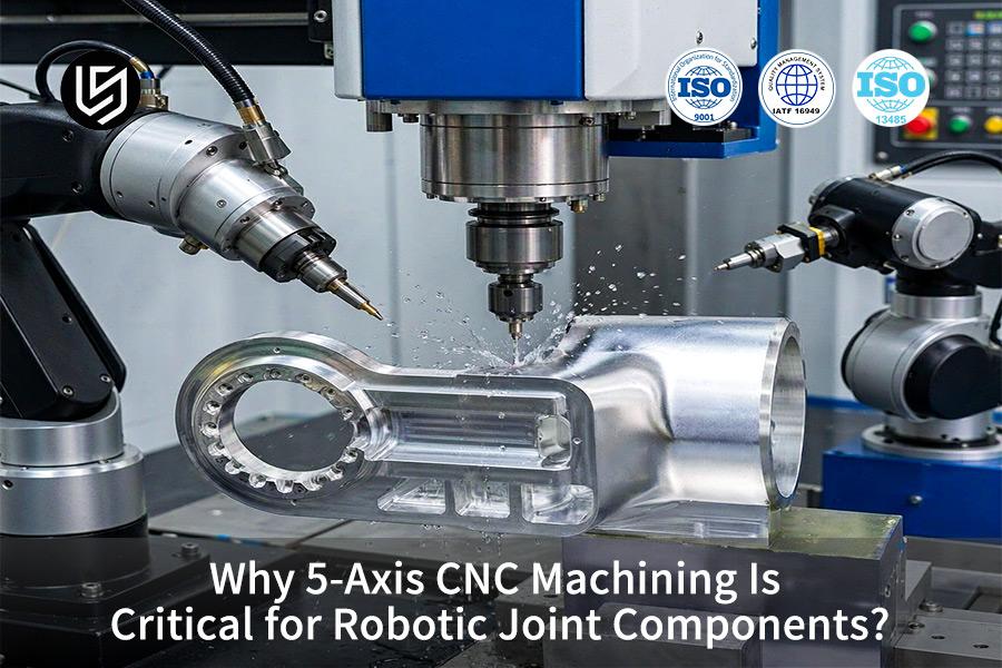
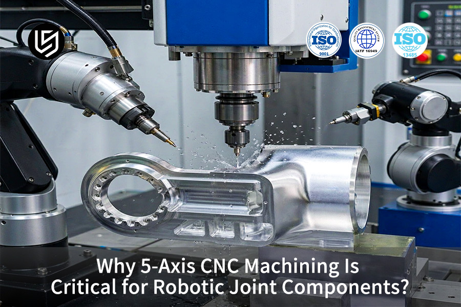
TL;DR: 5-axis robotic joint CNC machining is a material removal (subtractive manufacturing) process for actuator and rotary housing fabrication via one synchronous five-axis cutter path. With only one clamping setup rather than multiple setups, part relocation and positional stack-up no longer occurs. Final part geometry achieves tolerances of ±0.005 mm.
Newly minted junior mechanical designers and robotics engineers encounter a plethora of geometry terms long before the joint drawing review. Newcomers think that just because there’s additional rotation, the fit must be better, while the actual determinant is mostly the fixture rigidity and datum system used. 5 principles of positioning plus 1 tolerance gradient map indicate where tight tolerancing warrants the extra expense. Robotics engineers next determine if one setup with multi-axis machining makes sense.
Key Takeaways
- 5-axis CNC machining is a one-set-up manufacturing technology for joint housings. The movement of two rotary axes and three linear axes in one set-up makes the occurrence of spatial rotation inaccuracies impossible.
- Bore-to-flange coaxiality is a datum relationship that defines joint positioning precision. Multi-stage clamping is a process of dividing one bore-to-flange relationship into several set-ups and each movement creates additional deviation. Single-set-up coaxiality is an accuracy of a few microns.
- Joint material selection is a compromise between stiffness and inertial motion. 7075-T6 aluminum alloy is the main material selection for lightweight actuator bodies. Alloy steel hardened to 28-32 HRC (Rockwell C scale) is a stiffer alternative for heavyweight joints that require stiff bearing seats.
- Surface integrity is the result of chatter reduction in final passes. Feed marks indicate chatter, whereas fretting takes place in sealing surfaces. Surface roughness Ra 0.8 μm is a surface quality which protects harmonic drives and angular contact bearings from wearing out.
Why Trust This Beginner's Guide?
Gloria has more than 15 years of professional experience in machining and rapid prototyping in robot joint machining and used to teach cutting mechanics. Follow Gloria's Engineering Insights on LinkedIn carries further notes on kinematics for junior engineers. The nomenclature of robot joint coordinate systems can be found in ISO 230-1:2012 (verified 2023).
Datum logic, single setup contouring, and geometric tolerance uniformity were validated by the expert cutting application engineering team at LS Manufacturing. Classes of general tolerances ISO 2768-1:1989 give fundamental tolerance bands for each dimension in the illustrated robot joint. Full dimensional inspection delivers all values of dimensions to be analyzed.
Data source: LS Manufacturing 2025–2026 robotic joint manufacturing test data (Project ROBOT-2026-804; sample size >800). Every single figure is specific to a certain project range rather than the corporate average output level. The junior engineers have acquired the technique for understanding datum systems within multi-face joint drawings before starting the tolerancing procedure.
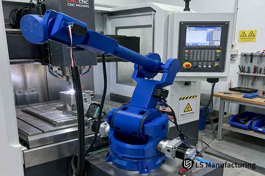
Figure 1: One industrial robotic arm works beside a CNC machining centre on an automated cell floor.
Why 5-Axis CNC Machining Is Critical For Robotic Joint Tolerances?
5-axis CNC machining is a synchronized contouring operation for micron-class mounting datums in robotic joints and eliminates re-clamping errors from assembly due to 5-axis cutter orientation. Multi-stage clamping can spend ±0.1 mm of one accuracy budget before cutting starts, which explains why 5-axis CNC is critical for robotics. 5-axis CNC (Computer Numerical Control) contouring ensures one continuous spatial relationship between cutter and workpiece. Machining in a single setup determines all bores' centers in one machine coordinate system, hence keeping coaxiality in relation to the datum reference. Planetary and harmonic drive (strain-wave gearbox) housings benefit most, while flat single-face plates gain nothing.
Geometric Closure Of Rotary Pairs And Axis Constraints
Robotic joint components machining tolerances start from datums and not surface finish. CNC machining tolerance standards like ISO 1101:2017 (section 8.2.3) define datum features (chosen surfaces or axes to use as measurement origins) for each bore on the joint drawing.
Six-axis wrists position the end within microns by distributing the error budget equally among all joints:
- Coaxiality (two holes on same axis) uses up most of it.
- Face runout (axial wobble under rotation) uses the rest.
Any kind of end-effector (robot arm gripper/tool) would experience drifting when there is an increase in coaxiality and runout.
Single-Setup Truncation Of Tolerance Stack-Up
Single setup CNC machining precision will resolve the centers of bores from a single fixture origin so that tolerance stack-up (part errors) no longer continues to increase. 3-axis mill resets datum of each housing on each flip and maintains an error of 0.1 mm class while 5-axis contouring maintains an error of 5-micron class coaxiality. To put it simply, one clamping centers all holes; further setups cause errors.
Tolerance band will identify the housings where 3-axis capability fails. Novices believe that adding axes will reduce all kinds of errors, but only one clamping causes accuracy because re-datuming increases error. CNC machining applications with crossed bores will have maximum errors due to multiple clamping.
What to Remember
- Assign one datum to bearing bores before assigning dimensions to any flange face.
- Bores using one datum can be combined into one clamping.

How Does Multi-Axis Machining Build Complex Robotic Actuators?
Multi-axis machining is one coordinated cutting motion where linear strokes and rotary tilt axes advance together. How 5-axis CNC works for complex geometries depends on vector interpolation (all axes advancing along one shared spatial path), where X, Y, Z moves share one interpolation cycle with A and B tilts. Rotation of the workpiece creates access angles rather than extra tool length, allowing short rigid tools to reach the inner areas of the joint. Even in the case of flank loading, when one edge of a tool cuts in conjunction with another, the finish will remain sub-micron class.
Vector Interpolation Across Five Machine Axes
5-axis CNC machining robotic joints performs X, Y, Z strokes and also performs A and B tilts using only one interpolation chain, and not as independent positioning operations. Controller look ahead combines all axes into one continuous stroke, which keeps the orientation of the cutting tool aligned with cavity walls.
- Linear strokes determine the cutter position.
- Rotary tilts determine one contact angle.
- Interpolation combines position and tilt in one cycle.
Overhang Control And Geometry Boundaries
Multi-axis machining robotic actuators counteract chatter by using short overhang, as cantilevered stiffness decreases as the cutter gets longer. Deeper thin-wall pockets cause beginners to use long cutters, but workpiece rotation reduces overhang.
In simple terms, any additional reach is achieved by moving metal and not by using long tools. How does CNC machining work in hollow cobot joints? Tilt access helps to explain that rotation turns a deeper pocket into a routing operation, not a cutter length operation.
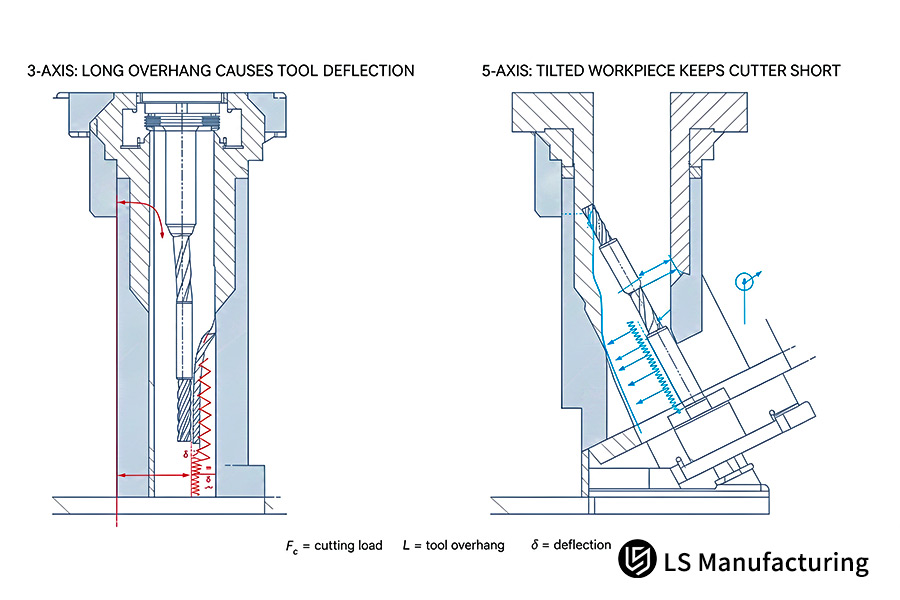
Figure 2: Cross section compares long 3-axis tool deflection with short cutters in 5-axis CNC machining robotic joints.
Basic Comparison Table
Four physical dimensions distinguish between three multi-axis routing sequences in robotically-driven joint cutting. Cutting geometry, coaxiality, datum coincidence, and part form represent all machining processes. Junior engineers refer to one table and map out each column to a family of parts.
| Dimension | Traditional 3-Axis Milling | Indexed 3+2 Axis Positioning | Continuous 5-Axis Contouring |
| Spatial geometry access | Only cutting in normal plane, no undercut or oblique oil grooves | Indexing and tilt, segmented cuts, cutter orientation angle fixed | Cutter orientation varies continuously with respect to surface normal of complex geometry |
| Coaxiality and datum coincidence | Flipping and re-indication manually, cumulative datum tolerance ±0.1 mm | Less flipping, indexing positioning tolerance ±0.03 mm | Clamping yields all rotary features, datum coincidence ±0.005 mm |
| Cutter overhang rigidity and chatter | Used cutters longer than 5:1 L/D ratio; deflection and chatter frequent | Medium length of cutters; mild marking observed for multi-axis transitions | Short and rigid cutters; even in flank milling, Ra = 0.8 μm surface quality |
| Typical robotic part forms | Flat joint base covers; mounting brackets without cable routing | Orthogonal bores in cubic reducers; external junction boxes | One-piece hollow joint flanges; routed-channel torque sensor bases |
Five-axis contouring is suitable for dynamic thin-walled kinematic joints, whereas three-axis milling is used for flat base covers and lower accuracy outer covers.
What Materials Are Best Suited For Machining Robotic Joints?
Robotic joint engineering materials are made up of metal alloys based on their stiffness to weight ratio, fatigue strength, and dimensional stability when subjected to reverse loading. Two families cover what materials are used in robotic joints: aerospace aluminium grades and quenched-and-tempered alloy steel. Cutting speed is related to the thermal conductivity and resistance of each alloy material. 7075-T6 aluminum requires the use of coolant and regulated feed otherwise residual stress will cause bowing of 1.5 mm thick walls.
Precipitation Hardening And Yield Strength In 7075-T6 Arms
Precipitation hardening (precipitation stops dislocations from moving once the alloy is aged) makes the 7075-T6 yield strength ≈80% higher than 6061. Aluminium and steel continue to be two CNC machining materials for the majority of robotic joint parts.
- Aluminium alloys dissipate heat quickly and have low density.
- Steel alloys handle reversing torque in compact sizes.
Specific stiffness (elastic modulus divided by density) is the reason why the 7075-T6 prevails in long reach robotic arms. 5-axis CNC machining robotic joints takes away the material from the thin sections in a single clamp, making the residual stresses symmetric. Simply put: lightweight robotic arms move faster without large engines.
Fatigue Life And Flank Wear In 42CrMo4 Steel
42CrMo4 (chromium-molybdenum alloyed steel) has maximum fatigue life when the material is tempered to 28-32 HRC after being quenched. The spline shafts handling reversing torque require hardened cores since the softer alloys undergo deformation when loaded repeatedly. One CNC machining process includes flood cooling with moderate feed when hardness increases.
Hard steel is not necessarily a sharper steel; flank wear is increased instead, leading to a need for slower feeds. Robotic joint components machining tolerances then require a fresh edge before the size gets too far out of tolerance. Engineers in their first job learn that hardness and machinability are not interchangeable terms.
Practical Takeaways
- Use 42CrMo4 only for spline shaft machining; not for flat covers.
- Ensure temper band for fatigue cycles prior to machining hardened bores.
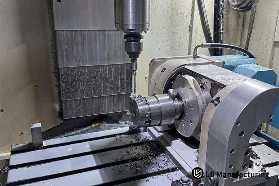
Figure 3: Rotary table rotates one cylindrical metal workpiece under a milling cutter with chips falling.
Which Factors Impact Single Setup CNC Machining Precision?
Single setup CNC machining precision is dimensional control which is attained when all six degrees of geometric freedom of the clamped piece are fixed in one coordinate system of the machine. Three major factors that influence size variation are thermal growth of machine parts, elastic deformation due to cutting forces, and micro-machining tool wear. ISO 230-1:2012 establishes geometric accuracy tests that quantify the individual contributions of each of the machine-related sources. Fixturing, servo control and symmetric helical approach eliminate size variation while keeping geometric tolerances within 5 µm envelope.
Kinematic Error Compensation And RTCP Control
RTCP (Rotation Tool Center Point, control holds tip position while a spindle head rotates) provides the foundation of five-axis machining. Servo systems take rotary axis feedback, change linear axes positions, and eliminate tip deviation due to head vibration. Manufacturers prove their compensation algorithms using ballbar and laser tests.
ISO 230-1:2012 specifies geometric testing techniques for rotational axes, including angular position error motion. 3-axis vs 5-axis CNC for robotic parts depends on one thing: does a rotary axis moves during cutting? Cutting requires motion compensation; indexing does not.
Cutting Heat Distribution And Thin-Wall Symmetry
Single setup CNC machining precision depends on heat escaping via chips, not being transferred into the aluminium blank. Layered symmetrical toolpaths relieve residual stresses evenly, preserve bore cylindricity. Consumers get an easy test to distinguish between thermal drift and tool wear in inspection results.
Robotic joint components machining tolerances become smaller after the finishing passes switch between walls. CNC machining principles dictate balanced stock removal rather than fast one-way roughing. To be more clear, metal removal in even layers will remain where it should be.
How 3-Axis VS 5-Axis CNC Dictates Robotic Parts Quality?
3-axis and 5-axis CNC milling are two stages in a freedom hierarchy that determine transmission backlash in robotic rotary joints. 3-axis vs 5-axis CNC for robotic parts comes down to a single question: is the tool able to reach deep bores without being extra long? Overly long cutters bend, therefore, tapered bores fall outside a 30 μm tolerance range. Ability of five-axis inclination to maintain constant tip speed eliminates vibration marks on deep walls. backlash (loss of motion between interlocking gears) will decrease as the bores remain cylindrical. Rotational bodies with two axes will receive no benefit because five-axis programming in this case would cost more than CNC turning (turning operation with the stock rotating while held against one fixed tool).
Spatial Freedom Limits And Transmission Backlash
3-axis machining works off the cantilevered deflection setup, therefore, tool travel alone is responsible for cavity access. The requirement of long boring tools for deep bearing holes results in the formation of tapers due to cantilevered deflection of round holes. Taper formation makes the axis of gears in the reducer to incline resulting in increased backlash in one drive train.
Why 5-axis CNC is critical for robotics is explained here: the rotary tilt allows deep wall machining with shorter tools, and, hence, bores are cylindrical. In less than two minutes the team can tell whether the risk of taper formation is due to tool travel or not.
Tilt Entry, Constant Tip Speed And Turning Boundaries
Multi-axis machining robotic actuators uses the constant tip speed during tilt entry. The constant cutting speed prevents chatter (self-excited vibrations between the cutter and wall) allowing for maintaining the same roughness of walls of 0.8 μm. For a novice, 5-axis precision depends only on one datum point.
Rotational bodies in their plain form disqualify one classification. What is CNC machining add to the lathe that rotates the workpiece against a single tool? Programmers generate more five-axis code than lathe code because they keep the two-axis part on the turning centre.
Transferable Lessons
- Measure the roundness of the bore at two depths before assuming the problem lies with machine accuracy.
- Use five-axis programming only on enclosed geometry and never plain two-axis parts.
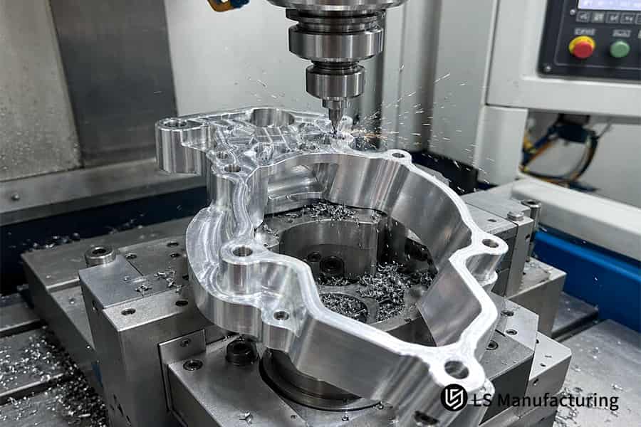
Figure 4: Fixture clamps one ring-shaped robotic joint flange while a rotating cutter removes metal.
How Multi-Axis Machining Works In Practice: A Cobot Joint Example From LS Manufacturing
Single-setup multi-axis CNC machining is the routing technique used to finish all of the rotary features in hollow cobot joints in a single clamping operation. A single 7075-T6 aluminum rotary flange 120 mm in outer diameter consists of a harmonic drive flexspline spigot and crossed roller bearing seat. Cables need to be routed inside the hollow bodies of collaborative robots, thus the walls have to remain thin due to the fact that the thickness cannot increase just to provide stiffness. Minimum thickness of cantilever walls is 1.5 mm, which means that both of the end bearing seats require coaxiality.
Application Scenario
How does CNC machining work inside hollow cobot flange? In cobots, cables run through the actuators, and one 7075-T6 flange must accommodate 1.5 mm cantilevers around the area of two bearing seats. Both bearing seats require precision coaxiality. Many young engineers wrongly believe that the problem is wall thickness.
Principle in Practice
Cutting speed (Vc, peripheral cutter speed) equals 60 m/min, as aluminum alloy 7075-T6 cools down quickly but becomes very soft at high temperatures; increased cutting speeds only increase temperature gradient, hence bending 1.5 mm thin walls. Tilt angle between spindle and A/C ensures even loading of short end mills. MQL (minimum quantity lubrication) equalizes temperature distribution within thin ring.
Measured Results
Setup time decreased by 14%, and first-article production and small batch production time was reduced by 12%. Accuracy of key bore coaxiality reached ±0.005 mm, and first-article defect rate was reduced from 18% to 4%. Thin-wall aluminum CNC machining benefits from fewer setups, as coaxiality errors accumulate, but not spindle speed.
Data source: LS Manufacturing 2025–2026 robotics joint machining test log (Project #ROBOT-2026-804, sample size >800), based on an internal measured database rather than plant-wide production averages.
FAQs
1. What is the primary reason robotic joints require 5-axis CNC machining instead of standard 3-axis mills?
Single setup 5-axis contouring routing allows finishing all rotary features in joint housings using only one clamping. Datum references are kept fixed for bearing bores, flange faces, and cable channels. Routing with three axes requires re-datuming one housing per each flip. Coaxiality is a location tolerance defined according to datum references in ISO 1101:2017. Coaxiality is within 5 µm under single setup routing. Design reviews allow predicting which housings require single clamping rather than counting axes.
2. Does utilizing 5-axis CNC machining always eliminate post-machining surface treatment requirements?
Anodizing is an electrolytic conversion coating process that creates aluminum oxide from base metals without adding new layers. Surface roughness characterizes peak to valley geometry, whereas coating thickness is responsible for corrosion resistance. 5-axis contouring leaves spigot faces with Ra 0.8 µm roughness. MIL-A-8625 standard provides classes of anodizing for aluminum alloys. LS Manufacturing joint shells get MIL-A-8625 anodizing after cutting. Procurement department needs to distinguish roughness values from coatings on one joint drawing.
3. What is the typical wall thickness limit when machining 7075-T6 robotic actuator housings?
Minimum machinable wall thickness becomes a stiffness limitation for resisting chatter in cantilevered sections. Such sections can bend due to cutting force, while residual stress will deform the finished sections once they get unclamped. CNC thin wall machining of such joint shells takes into account LS Manufacturing engineering specifications holding cantilevered walls at ≥1.5 mm; ASTM B209-14 specifies 7075-T6 aluminium plate and sheet.
4. Can 5-axis CNC machining completely replace EDM for complex internal joint features?
Electric discharge machining represents a thermal erosion process where metal gets removed due to the spark between the electrode and one workpiece. Spark erosion does not involve any cutting force, and fragile sections remain intact. Rotating end mills create corner radius equal to cutter size, while R0 internal corners go beyond the milling range. According to ASM Handbook Vol. 16 (Machining), spark erosion belongs to non-traditional processes, and LS Manufacturing process sheets assign R0 corners to EDM operations.
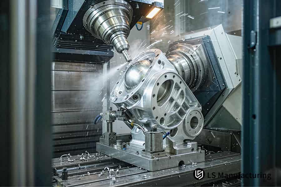
Figure 5: Coolant sprays one robotic actuator housing as cutters machine bores, bosses and ribs.
Summary
Repeatability of the kinematic joint and the durability of its operation are determined by the geometric accuracy of the spatial mounting datums and the stability of a single set-up fixture. LS Manufacturing uses well-proven machining principles and multi-axis kinematics to provide new robotics engineers with baseline geometric tolerances before scaling up to production.
Robotic Machining & Kinematic Engineering Support
For discussions of engineering education, geometric tolerance allocation analyses, and kinematic analysis of multi-axis toolpaths for robotic joints, get in touch with LS Manufacturing's Application Engineering at info@lsrpf.com or +86 185 6675 9667.
Further Reading: 5-Axis CNC Machining For Robotic Arm Joints: Precision Solutions For High-Load & High-Precision

