 English




TL;DR: Sheet metal vs CNC machining electronics housings comes down to two limits. CNC milling holds ±0.008 mm on mating faces while precision sheet metal holds ±0.02 mm after springback correction; above 85 lifetime units a $1,200 forming tool makes sheet metal 32.1% cheaper per unit ($28.50 vs $42.00 at 500 units). Seal grooves and stepped walls route to CNC; uniform 0.8–3.0 mm covers above 85 units route to sheet metal.
R&D engineers for electronics with tooling budget constraints end up with late changes in designs due to the fact that enclosure geometry rules out sheet metal fabrication or CNC machining. Wall thickness uniformity and the land surface for gasket sealing determine the routing of enclosure manufacturing process before quoting can be provided. A 4x4 matrix along with the decision tree determine one way in five minutes. In brief, fitting the volumes and fit of parts to one process will ensure no unexpected tooling costs.
Why Trust This Manufacturing Comparison? Practical Insights From LS Manufacturing
By Gloria Wu, Rapid Prototyping and Rapid Manufacturing Expert at LS Manufacturing with 15+ years in multi-process prototyping, all comparisons below have been written. Examine Gloria's engineering decision framework that documents her cross-process approach. LS Manufacturing performs multi-axis CNC machining, 3D printing, and sheet metal in-house.
ASME Y14.5-2018 defines all the GD&T (Geometric Dimensioning and Tolerancing) requirements for both processes. For the sheet metal and CNC, there is only one standard version, one setup, and one window.
ISO 9001: 2015 governs the Zeiss CMM and Mitutoyo roughness testing of both processes. Every audit tracebacks every report to the equipment and particular standard. LS Manufacturing performs multi-axis CNC machining, 3D printing, and sheet metal in-house.
Data source and reference: senior process engineer review at LS Manufacturing involved all figures, with both processes specified by one standard version, one setup, and one window.
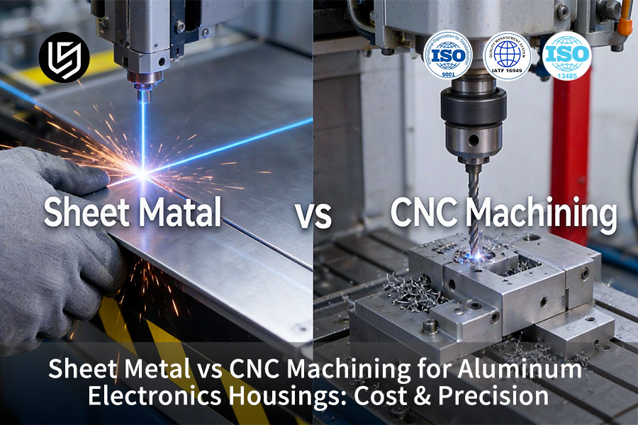
Quick Reference 4×4 Comparison Matrix
Four distinct engineering aspects differentiate the precision sheet metal from precision CNC milling of the aluminum enclosures to contain the electronics circuitry. The enclosures are made of AL 5052 and the housing of AL 6061-T6 select a pair from a cross-process database sample over 1,500. You should budget for the 14.5% forming reject base — it carries more schedule risk than the 1.9% milled reject rate.
| Dimension | Option A: Precision Sheet Metal | Option B: Precision CNC Milling | Threshold / Recommended Scenario |
| Fit Accuracy and Tolerance | Precision grade ±0.02 mm; bend angle ±0.5° | Precision grade ±0.008 mm; contour ±0.003 mm | CNC for mating surfaces ≤±0.01 mm or seal grooves |
| Material Use and Wall Form | Uniform wall, nominal 0.8 mm–3.0 mm, AL 5052 | Variable wall; stepped walls, heat fins, AL 6061-T6 | CNC for wall span >1.5 mm or heat fins |
| Unit and Volume Cost | 500-unit baseline $28.50/unit; tooling $1,200 | sheet metal 32.1% cheaper above 85 units ($28.50 vs $42.00) | 85-unit crossover: CNC below, sheet metal 28% cheaper above |
| Lead Time and Iteration Speed | Prototypes in 7 days; blanking and bend tooling setup | Prototypes in 4 days; CAM-driven cutting, no tooling | CNC for design churn; sheet metal for frozen production |
CNC milling gives mating faces with ±0.01 mm tolerance; precision sheet metal gives frozen runs with $13.50 savings/unit at 500 units.
Mobile Note: Matrix will scroll to left or switch to card mode for narrow display.
Key Takeaways
- Threshold of Cost Efficiency: No need of tooling makes it more cost effective to machine at small quantity production. As quantity rises, amortization of tooling tilts the order and forming of enclosures becomes cheaper unit wise.
- Wall Thickness and Geometry Limitations: Stepped wall thicknesses and deep blind cavities make it mandatory to cut from a solid billet. Uniform thin wall enclosures can be formed as only one gauge can be bent into an enclosure.
- R&D and Validation Workflow: The phase of design churn requires cutting without tooling setup. Frozen geometry requires the forming of enclosures through press brake with shorter cycle time than machining hour cycles.
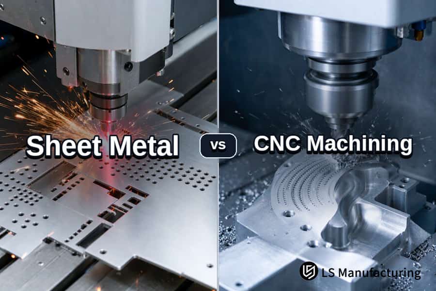
Figure 1: Left: Bending springback illustration + ±0.02 mm; Right: Milled surface Ra 0.4 µm
Which Process Delivers Tighter Precision For Enclosures?
Enclosure dimensions with ±0.01 mm fit requirements with sealing rabbets distinguish sheet metal vs CNC precision tolerances results before taking into consideration unit cost factor. CNC machining precision tolerance is of ±0.008 mm; precision sheet metal tolerance is restricted to ±0.02 mm tolerance after springback correction (elastic recovery after bending). Sealed enclosures favor CNC machining; unsealed covers favor precision sheet metal. Conventional machining holds ±0.05 mm on formed parts and ±0.03 mm on milled parts; ultra-precision cavity positioning reaches ±0.003 mm in milling. Milled surfaces have Ra (arithmetic average roughness) of 0.4 μm compared to 0.8 μm of cold rolled sheet. Grain orientation introduces anisotropy to any bend; subtractive machining technique eliminates this limitation. Microwave shielding cavities choose machined vs sheet metal electronics enclosures on the basis of milling process. ASME Y14.5-2018 and Zeiss CMM MPEE 0.7 + L/400 µm control both techniques.
Tolerance Grades Across Four Production Levels
- Conventional tolerance grade: ±0.05 mm for precision sheet metal vs ±0.03 mm for CNC machining.
- Precision fit tolerance grade: ±0.02 mm for precision sheet metal vs ±0.008 mm for CNC machining.
- Ultra-precision cavity: ±0.01 mm after secondary finishing vs ±0.003 mm for CNC machining.
- Surface finish: Ra 0.8 µm for cold-rolled sheet metal vs Ra 0.4 µm for milled faces.
CNC machining tolerance standards under ASME Y14.5-2018 make both technologies similar.
Where Formed Enclosures Still Win
Both covers and guards prefer sheet metal vs CNC machining electronics housings due to the Ra value of 0.8 µm being sufficient for aesthetic surfaces. In other words, each quote needs its own tolerances and its own calibrated machine.
Related keywords: sheet metal vs CNC tolerance grades / enclosure sealing rabbet precision / CNC machined Ra finish
Data source and benchmark: per ASME Y14.5 geometric dimensioning and tolerancing specification and Zeiss CMM measurement verification report, indication error MPEE: 0.7+L/400 μm.

When Does Sheet Metal Beat CNC On Total Production Cost?
Sheet metal forming is a more economic process than CNC machining on a per unit basis when the production quantity exceeds 85 units and when the walls of the enclosure do not vary. Volume decides the cost gap between sheet metal and CNC machining until tolerance-driven tooling cost takes over. The cost of tooling for forming that is $1,200 over 500 units will be $28.50 for the formed enclosure, while the housing that is machined will be $42.00. Sheet metal fabrication is better for uniform wall enclosures above 85 units; while CNC machining is preferable for stepped wall enclosures below 85 units. Chip loss and not the machine hour rate makes the rigid cost of the machined housing at volume level.
Material Yield and Machine Hours
CNC machining bills machine hours to remove most of the purchased billet weight; sheet metal forming buys blank area instead. Low volume CNC machining does not incur any tooling expenses because CAM software controls the tools directly from the CAD drawings. Sheet metal vs CNC for prototyping is inverted because modifications favor toolless milling.
Four-Step Conversion Review
- Compute life-time volume and make sure the demand exceeds 85 units.
- Distribute $1,200 among the units and ensure the amortization per-piece does not exceed $15.
- Pick out housings for which the material removed is more than 50% of the initial billet mass.
- Go from cutting to blanking and bending as soon as all the conditions are fulfilled.
Stepped walls and sealing lands allow for an inexpensive cut at the beginning. CNC machining DFM guidelines decrease cycle time until volumes are reached, and when to use sheet metal vs CNC is a matter of volumes once geometry is stabilized. Lifetime volume prediction for the buyer pulls the cost curve farther than price per unit does.
Related keywords: sheet metal vs CNC unit cost / CNC chip loss vs material yield / 100 unit conversion review
Data source and benchmark: based on LS Manufacturing 2025–2026 cross-process measurement database (sample size >1,500), calculated under project numbers #MED-2026-084A and #MED-2026-084B.
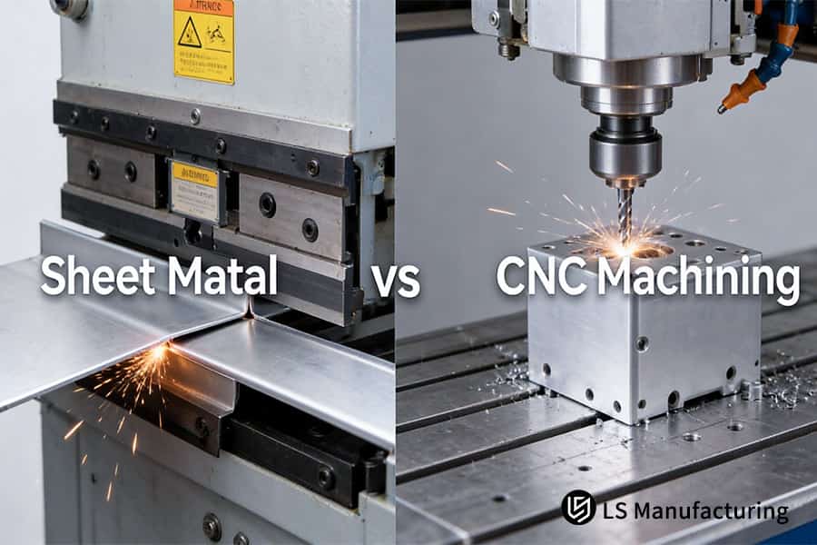
Figure 2: Sheet metal punching forms hole arrays in AL 5052 while CNC machining drills AL 6061-T6 mounting bosses.
How Do Wall Geometry and Internal Complexity Impact Feasibility?
Wall geometry and internal feature topology set a physical hard constraint behind aluminum enclosures sheet metal or CNC decisions, not supplier preference. Uniform thickness sheets of 0.8 mm – 3.0 mm AL 5052-H32 should be bent, while stepped walls from 6.0 mm bottom walls to 1.5 mm thick sidewalls require multi-axis milling of solid AL 6061-T6 blocks. Forming creates an inner bend radius only of ≥1.0 x gauge, and that is why it is impossible to form blind slots and seals grooves. The presence of bosses and a gauge change necessitate CNC machining; even covers and ventilation holes may become CNC due to uniformity.
Gauge Continuity and Bend Limits
Sheet metal vs CNC precision tolerances depend on wall length even before any cutter begins spinning: constant 1.0 mm–3.0 mm thick covers use formed material while stepped 6.0 mm-to-1.5 mm walls use milled material. Strained H32 temper is required to prevent cracking of AL 5052-H32.
Internal Feature Routing
- Internal geometry determines machined vs sheet metal electronics enclosures quicker than wall length.
- Stepped slots and O-ring grooves: milled roots protect seal depth; forming does not create either of those.
- Countersinks and bosses: one milled set-up accommodates both; forming requires fasteners.
Hybrid Split Lines
Aluminum CNC machining possesses thermal mass; forming possesses airflow. Simply put, geometry continuity chooses a route before cost considerations.
Related keywords: enclosure wall geometry feasibility / CNC milled internal bosses / sheet metal vent pitch limits
Why Are Failure Rates Different In Sheet Metal VS CNC Housings?
CNC machining vs sheet metal enclosure failure rates differ due to defects' origins, not inspection gates. CNC machined pieces of work fail because of distortion that results from releasing of the locking stress after the machining process. The reject rate is 11.2% for machined housing. Sheet metal enclosures fail because of drift of bend angle and poor installation of self-clinching fasteners caused by wrong hole alignment, hence a rejection rate of 14.5%. Machining of thin-wall parts and bending needed for forming the parts need upstream controls prior to having fewer rejects. Stress relief tempering (second heating process between roughing and finishing) and phased roughing reduce the rejects of machined parts to 1.9%. Laser bend angle correction and torque control installation cut down rejects of formed parts to 2.8%. Sheet metal vs CNC precision tolerances become evident through yield exposure, and sealing surfaces justify this investment.
Removal of bulk in machined housings through pocketing removes stress equilibrium that keeps the thin floors flat. Angle errors in formed housings come from grain direction. 5-axis CNC machining reduces setups to one and this results in fewer reclamping errors. Formed enclosures start from a higher reject base even though their geometry is simpler.
Process Controls That Converge Both Rates
- Roughing staged: keep finishing allowance, then temper after final cutting.
- In-process laser angle measurement: adjust the angle for each bend then proceed to next bend.
- Presses with torque control: set torque limit per insert specification.
- Clamping sequenced: stress-relieve faces first then finish them.
Multi-axis CNC machining reduces reclamping errors but requires angle feedback for forming to reduce to 2.8%. When to use sheet metal vs CNC becomes a yield issue as the number of fastener and seal lands increase. From a purchasing perspective, 14.5% rejection base presents more scheduling risks than 1.9%.
Related keywords: housing defect rate comparison / stress relief vs angle compensation / fastener torque failure modes
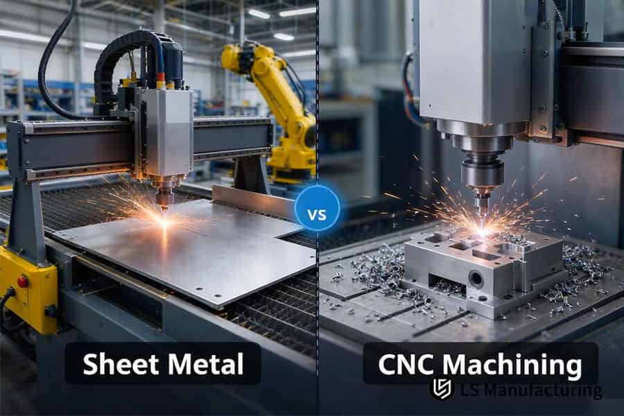
Figure 3: Sheet metal fabrication cuts AL 5052 panels while CNC milling removes AL 6061-T6 chips for electronics housings.
How Does Prototyping Lead Time Compare Between The Two Methods?
In 1-5 unit builds, CNC machining saves up to 30%-45% in delivery time compared to sheet metal fabrication, since CAM programs machine stock AL 6061-T6 without the need for any tooling. Formed prototypes are put through blanking, deburring, bending setup, and fastener attachment procedures, which means that 7 days will pass compared to 4 days spent on milled prototypes. CNC machining owns prototype schedules while interfaces stay unfrozen; sheet metal fabrication owns repeat runs once tooling exists. Final inspection is done with CMM and vision projection. Sheet metal vs CNC for prototyping decisions start from calendar risk.
Why Unfrozen Designs Favor Cutting
Startup R&D process does not freeze circuits until fit is verified, hence the decision to choose between sheet metal vs CNC machining electronics housings is in favor of cutting.
Tool-less CNC machining eliminates each revision from the 4 days cycle, thus giving designers back 42.8% of the waiting time with each iteration.
Sheet metal vs CNC machining cost comparison comes into play only once all interfaces are frozen. Simply put, the calendar risk dictates the prototype flow.
Related keywords: prototype lead time comparison / cnc prototype turnaround days / sheet metal bend setup time
What Hybrid Strategies Combine Sheet Metal And CNC Advantages?
Hybrid construction combines CNC-milled load-bearing cores and formed sheet metal covers, making aluminum enclosures sheet metal or CNC no longer mutually exclusive options for medical and automation housings. CNC milling maintains datums for sensors, grooves for O-rings, and bosses for heat dissipation to ≤0.01 mm of flatness, while formed 1.5 mm AL 5052 panels form the airflow area. Hybrid construction is preferred when sealing and rigidity come together in a certain area; single-path construction is preferred when geometry is uniform. Programs achieve IP65 (IEC 60529 dust-tight and water-jet protection rating) targets lower structural costs than pure-milled designs. When to use sheet metal vs CNC becomes a trade-off based on the number of parts when seals and vent areas are the same enclosure. ASME B1.1-2019 covers 1/4-20 UNC threads locking the covers.
Feature Ownership Across Two Halves
CNC-milled cores have datums for sensors, O-ring grooves, and thermal bosses; formed covers have vent louvers, bottom trays, and I/O panels. CNC machining sensor mounts ensure datums remain within sub-10 microns, while formed 1.5 mm AL 5052 panels ensure ±0.05 mm positional datums. Machined vs sheet metal electronics enclosures differ by function, so that dowel pins provide alignment.
Joining Interfaces That Absorb Tolerance
Dowel pins establish cover position prior to closure by fasteners, ensuring that drift does not affect seal lands. PEM fasteners float slightly under clamp loads and avoid distortion of milled bosses. Assembly crews now have a single repeatable stack-up instead of two tolerance stacks.
Where Hybrid Builds Pay Back
Hybrid builds incur extra labor for joining and extra fastener costs. Small production lots call for a single build route, since additional assembly steps negate any material savings. IP65 builds favor CNC-milled cores within formed covers, due to 1/4-20 thread CNC machining removing clamp load from seal lands.
Related keywords: hybrid enclosure construction / milled core formed cover split / pem fastener tolerance absorption
Decision Tree Framework
Sheet metal vs CNC machining electronics housings assessment begins with fit tolerance and then follows into wall geometry, lifetime volume, and hybrid structure requirements. Physical and geometrical requirements precede economical considerations on all branches.
Four nodes route every enclosure:
- Node 0 – Under 20 units with organic or lattice internal geometry: route to 3D printing instead of either process, because tooling-free additive builds avoid the $1,200 forming tool and the machine-hour floor of CNC milling.
- Node 1 – Do mating faces require ≤±0.01 mm fit or do they have a seal groove? Yes → precision CNC machining. No → Node 2.
- Node 2 – Does wall thickness change sharply or are there deep cavities with heat fins? Yes → precision CNC machining. No → Node 3.
- Node 3 – Lifetime volume is larger than 85 pieces? No, ≤85 pieces → CNC rapid prototyping. Yes, >85 pieces → precision sheet metal fabrication.
- Node 4 – Large outer casing works together with internal precise sensor datums? Yes → hybrid process with CNC core and sheet metal shell. No → usual precision sheet metal forming.
CNC machining applications include tolerances as well as high volumes, so hybrid routing remains available as long as datums and ventilation areas coincide within the same enclosure.
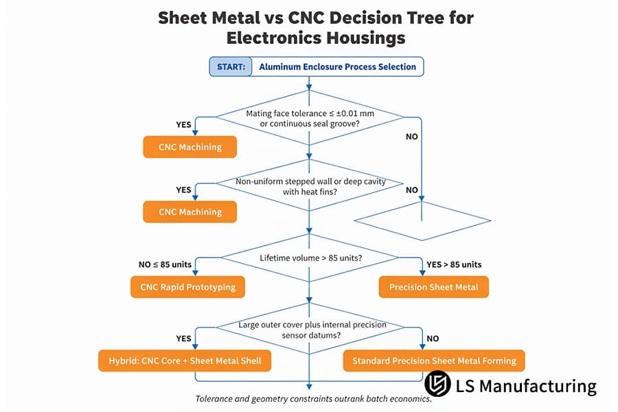
Figure 4: Sheet Metal vs CNC Decision Tree for Electronics Housings.
LS Manufacturing CNC Machining VS Sheet Metal For Medical Diagnostic Enclosures: Precision & Cost Optimization
Portable blood analyzer enclosures pit CNC machining process to the sheet metal fabrication process with the distribution of functionality on the faces of the enclosure determining which one is adopted. CNC machining process of Solid AL 6061-T6 allows the production of flat thermal pads and continuous shielding seams but most of a billet has to be hollowed out at a cost of $165.00 per part on a 300 unit prototype run. Sheet metal fabrication creates covers and I/O panels using minimum cost of material with a cost of $118.80 per part on the forming of the covers after wrapping around a milled base plate. Hybrid Construction is the better option where thermal and datum functions are localized while single route construction is the preferred option where every face bears datum or sealing function.
Initial Route and Pain Points
When designing the body of a 320 mm × 210 mm × 95 mm analyzer for an in-vitro diagnostics company, they opted for the monolithic 5-axis CNC machining process in the hope of ensuring shielding continuity and assembly alignment since all components would be manufactured from a one-piece billet. Pilot costs did not add up; while thin-wall bases warped when stress was relieved. 14.5% of bodies could not fit the motherboards.
Process Comparison and Decision
Feature mapping split one billet into two pieces. Medical CNC machining kept the sensor base plate, thermal pad, and dowel datum while sheet metal forming handled the covers and I/O panels.
Measured Outcomes
Hybrid routing cut enclosure cost by 28.0% versus monolithic milling; delivery time was cut down by 38.6%, going from 14 days to 8.6 days; percentage of assembly rejection dropped from 14.5% to 2.8%. Dowel interference became non-existent after the implementation of compensation and chamfers into the manufacturing process. Assembly-interference rejects in the incoming inspections became zero, and the projects gained days in the schedule, lost in cutting queues.
Validation and Lessons
1,000-hour runs for shielding stability on hybrids have been completed successfully, and the ISO 13485 audits have been passed for Project #MED-2026-084A and Project #MED-2026-084B. Precision CNC components continue to serve their functions as thermal and datum components in all analyzers, therefore, hybridization allows cutting only functional areas of the parts. Single-route cutting remains accurate when shielding continuity is required for all seams. Simply put, redundancy of geometry rather than process loyalty determines the enclosure cost.
"Splitting one billet into a formed cover and milled base plate saved 28.0% of the enclosure cost while maintaining the shielding continuity." — Mechanical Design Lead, in-vitro diagnostics, Project #MED-2026-084A
Data source and benchmark: LS Manufacturing cross-process measurement database, Project #MED-2026-084A (sheet metal cover) / Project #MED-2026-084B (CNC thermal base plate), sample size >1,500.

FAQs
1. Which process provides superior RF and EMI shielding for electronics housings?
Monolithic CNC machining is chosen for shielding continuity, whereas formed sheet metal is chosen for material cost on vented covers. Bent joints expand up to ±0.02 mm until conductive gaskets and reduced bolt pitch seal off gaps. Joint fit conforms to ISO 286-1:2010, and quality controllers audit CNC machining RF shielding results against Project #MED-2026-084A at LS Manufacturing.
2. What is the exact cost breakeven point between sheet metal and CNC for aluminum boxes?
Sheet metal is more cost-effective above 85 units crossover point, whereas CNC is more cost-effective below this threshold. Absence of tooling costs makes unit CNC machining unit cost cheaper throughout the validation process; later nesting blanks reduce unit costs by more than one-fourth.
Data Source: LS Manufacturing quotation database.
3. Can sheet metal achieve an IP67 waterproof rating for outdoor electronics?
IP67 is achieved with less rework with CNC machining, while IP67 is achieved with lower material cost with sheet metal fabrication. Gasket grooves that have been milled contain seal lands within a band <10 microns. ISO 2768-1:1989 specifies the formed tolerance, and the OEM assembly line submits fewer warranty claims about the milled seal lands.
4. How do I quickly decide between sheet metal and CNC for a new enclosure?
Two criteria determine enclosure routing: mating fits tighter or equal to ±0.01 mm, and lifetime volume relative to 85 units. Close tolerance fits and step-wall designs point to CNC machining; consistent thin walls greater than 85 units call for sheet metal. Both drawings are controlled by ASME Y14.5-2018, and the project scheduling data in LS Manufacturing 2025-2026, sample size >1,500, reflect both cut-offs.
5. Are aluminum materials identical between sheet metal stamping and CNC milling?
AL 5052-H32 is used for sheet metal stamping due to its formability, and AL 6061-T6 for CNC milling because of chip flow and stiffness. Stamped panels contain uniform 0.8 mm-3.0 mm walls; CNC milled billets start from 6.0 mm base plates to 1.5 mm sidewalls in one component.
Data Source: ASM Handbook Vol. 2.
6. What is the risk of tight tolerances causing dimensional distortion in thin sheet metal?
Formed panel bending springback of 1%-2% drives hole pitch variation into the ±0.05 mm range, while secondary CNC reaming brings hole pitch down to within 10 microns. Assembly teams arrange their reaming process after the form process not before, reducing rework time spent. ISO 2768-m: 1989 grades establish tolerances for the formed panel, while LS Manufacturing 2025-2026 sample size >1,500 documents both numbers.
Data Source: ISO 2768-1:1989, general tolerances — part 1
Summary
Thin-walled consistent enclosures designed for recurring orders qualify for precision sheet metal fabrication; stepped wall or gasket sealed enclosures should be machined using CNC machining. Hybrid routing process caters for enclosures dividing sealing from ventilation function.
Tolerance and budget calls start at design. Upload your 3D/2D drawing and LS Manufacturing tooling engineers return a routing assessment within 2 hours: +86 185 6675 9667 or info@lsrpf.com, while cross process selection papers are available at https://lsrpf.com/. In brief, one routing process determines which enclosure is right and sheet metal vs CNC enclosure RFQ checklist guides further purchasing process.

