 English



TL;DR: Fiber laser cutting is a non-contact thermal separation process for EV battery enclosure panels, where a high-pressure coaxial jet of nitrogen gas evacuates the molten metal puddle to ensure oxide-free, weld-ready cut edges. Dimensional tolerances for 1.5 mm–4.0 mm aluminum components reliably hold between ±0.03 mm and ±0.05 mm under ISO 9013:2017 standards, while sub-±0.01 mm features require secondary CNC machining.
Warped tray frames frequently baffle junior hardware engineers and procurement specialists when inspecting EV battery assembly lines. A common beginner misconception assumes that cutting force bends the aluminum, even though laser cutting involves zero mechanical tool contact. In reality, thermal distortion stems from unbalanced heat dissipation, optical absorption dynamics, and gas flow boundary layers. Mastering these three interactions reveals exactly when a laser-blanked edge is weld-ready and when secondary CNC machining becomes necessary for leak-tight pack sealing.
Why Trust This Beginner's Guide?
Gloria, the company's senior engineer with 15+ years of experience in precision engineering and rapid prototyping, provides EV enclosure training and leads manufacturability review for junior hardware team members. Follow Gloria's Engineering Insights on LinkedIn. Engineering Committee of LS Manufacturing evaluated the logic of drawing callouts prior to publication.
Drawing callouts follow ASME Y14.5-2018 standard that is a standard for dimensioning and tolerances in the United States. Therefore, a tolerance of ±0.035 mm of the table repeatability on aluminum trays is measured against one published rule. Distortions are obtained from the results of test log of LS Manufacturing Project.
In Fundamentals of Modern Manufacturing (Mikell P. Groover, 7th Edition), thermal cutting principles illustrate how transient heat conduction alters structural temper in 6000-series aluminum alloys. When design engineers attempt to enforce micron tolerances across every contour, non-uniform heating inevitably degrades overall flatness. Performing bare-blank optical inspections early allows teams to isolate beam-induced thermal distortion from subsequent fixturing misalignment.
How Does Fiber Laser Cutting Work in EV Battery Trays?
In EV battery trays, fiber laser cutting is a thermal, non-contact process for shaping 1.5 mm–4.0 mm aluminum sheet via a focused 1.06 μm beam. To truly understand how fiber laser cutting works, consider that the beam operates at 1.06 μm, while the longer 10 μm CO2 laser wavelength has poor absorption by aluminum, causing lower coupling efficiency.Mastering the fiber laser cutting battery tray process requires coordinating beam intensity with gas delivery. High-pressure nitrogen, 1.6 MPa to 2.0 MPa, blows away molten metal and protects the cut from oxidation. In 1.5 mm–4.0 mm aluminum trays, fiber laser cutting avoids tool wear, but CO2 laser cutting loses energy on reflective aluminum.
Optical Absorption and Beam Dynamics in Aluminum Alloys
The foundational laser cutting working principle aluminum applications rely on starts with absorption, and fiber laser vs CO2 laser aluminum cutting explains the gap: fiber laser wavelength at 1.06 μm leads to greater aluminum absorption at room temperature.1.5 mm–4.0 mm aluminum sheet reaches its melting point faster in a fiber laser, but slower in a CO2 laser with higher reflection rate.
The Dual Role of High-Pressure Assist Nitrogen
Fiber laser cutting tolerances for beginners start with kerf width, and kerf width tracks gas ejection. Nitrogen assist at 1.6 MPa to 2.0 MPa displaces oxygen, so cut faces stay weld-ready without oxide scale. Gas momentum blows molten aluminum from the kerf and stops dross from sticking, and aluminum laser cutting 6061-T6 depends on the nitrogen action to keep tray flanges clean.
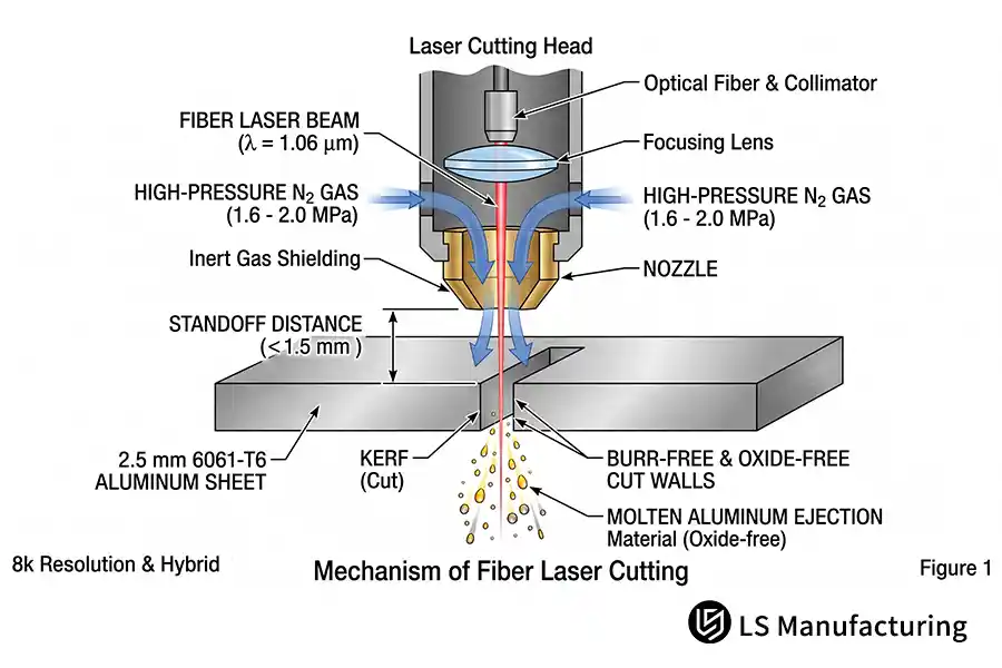
Figure 1: Schematic of the fiber laser cutting working principle in aluminum, illustrating the 1.06 μm beam, nozzle standoff distance (≤1.5 mm), and 1.6–2.0 MPa nitrogen assist ejection.
What Is Linear Profile Tolerance in Laser Cut Trays?
Linear profile tolerance in laser cut trays is the allowable deviation of the laser-cut edge from its CAD nominal profile, serving as a practical battery tray cutting tolerance guide where fits vary from ±0.01 mm to ±0.05 mm.Those seeking the answer to linear profile tolerance will refer to established laser cutting tolerance standards such as ISO 2768-m/f (ISO 2768-1:1989 general tolerance classes, m - medium, f - fine). Fiber laser cutting tolerances are ±0.05 mm on general tray profiles and long flanges, while computer numerical control (CNC) milling tolerances are ±0.01 mm on bolt-hole centers and module locating faces. Sealing faces and bolt-hole centers must have the ±0.01 mm side; simple outer blanks are ±0.05 mm.
ISO 2768-m/f Baseline Bands for Tray Outlines
Fiber laser cutting tolerances for beginners differ in the two bands according to the features: ±0.05 mm on perimeter blanks and non-sealing edges, and ±0.01 mm on bolt-hole centers with sealing gaskets. The repeatability of worktables within the ±0.05 mm band determines both. Hole sizes for laser cutting place bolt-hole centers within the band, laser cutting tolerance CMM inspection confirm the split.
Backlash and Kerf Width Effects on Final Tolerance
Backlash of servo systems, which is loss of position when the drive turns around, feeds error into the tolerance of the manufactured parts, and kerf correction moves every edge inwards or outwards. It is the error of movement rather than laser power that defines the minimum tolerance of long tray flanges.
Where Laser Cutting Stops and CNC Milling Starts
Beginners frequently call out an unachievable ±0.01 mm tolerance across entire tray perimeters. Over long battery tray flanges, cumulative thermal diffusion naturally expands edge deviations toward ±0.05 mm. Consequently, secondary CNC milling remains mandatory for tight mating interfaces and module locating bores requiring tolerances tighter than ±0.01 mm, whereas laser cutting efficiently handles the remaining baseline geometry.
Baseline Comparison Table: Manufacturing Precision and Process Attribute Gradient of Battery Trays
Four manufacturing dimensions separate conventional grades from precision grades in aluminum tray cutting, and rows pair measurable process attributes with pack-assembly service conditions. HAZ width (heat-affected zone, meaning solid base metal that softens without melting) marks distortion risk, so kerf width alone never predicts warping. Junior engineers read a single row and match sealing faces to process grades.
| Process attribute | Legacy baseline | Standard grade | Precision grade |
| Standard linear tolerance | Double a ±0.05 mm band | ±0.05 mm | ±0.01 mm, tightened by compensation |
| Surface roughness (Ra) | Two roughness grades above precision-grade finish | One roughness grade above precision-grade finish | Ra 3.2 μm |
| HAZ width | Widest thermal band observed | Roughly midway between legacy and precision bands | ≤0.08 mm |
| Typical application | Tray perimeter blanking, shield plates | Module mounting plates, vent-valve holes | Cooling-channel openings, seal-fit grooves |
To sum up, standard cut 0.05 mm cut work is for large tray outlines, and precision 0.01 mm work for cooling-channel openings and seal-fit grooves.
Why Does Heat Affected Zone Cause Tray Distortion?
HAZ is the narrow band beside a laser cut where 6000-series tray alloy softens and changes phase without melting. Why does heat affected zone cause tray distortion? Dynamic power modulation holds HAZ depth at 0.08 mm on 1.5 mm-4.0 mm aluminum, whereas a constant-power pass pushes HAZ to nearly double the 0.08 mm control depth on the same blank. Asymmetric transverse expansion builds residual stress once cooling lags behind beam travel. Corner dwell sets peak heat, heat affected zone laser cutting tips start with dwell time, not travel speed. HAZ depth, not cutting force, decides whether a large-span tray stays flat.
Thermal Gradients and Metallurgical Weakening
Heat affected zone (minor distortion due to uneven heat flow as described in ASM Handbook Vol. 16 on machining and thermal cutting) when 6061-T6 (solution heat treated then artificially aged) is cut, strengthening precipitates are lost in the vicinity of the cut, providing only local tensile stress (alloys similar to 6061-T6). A 1.5 mm wall radiates heat much quicker than a 4.0 mm wall, so transverse expansion remains unbalanced.
Reduce HAZ by Dynamic Power Adjustment
Assist gas selection in fiber laser cutting sets a second lever: at 1.6 MPa to 2.0 MPa, nitrogen assist gas stays inert, whereas oxygen assist at the same pressure adds exothermic heat and dark oxide. Dynamic power modulation drops duty cycle at corners and deceleration points, holding HAZ depth at 0.08 mm. High-aspect-ratio small hole laser cutting concentrates beam energy and calls for the same duty-cycle cut. In real use, a 0.08 mm HAZ keeps long thin-wall tray edges flat.
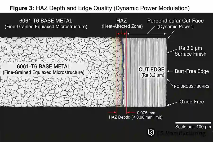
Figure 2: Microscopic cross-section of 6061-T6 base metal cut with dynamic power modulation, maintaining an HAZ depth of 0.075 mm (<0.08 mm limit) and an oxide-free Ra 3.2 μm edge.
How To Control Laser Cutting Tolerances in Battery Enclosures?
Closed loop calibration of beam focus, kerf compensation and assist-gas flow field. How to hold the laser cutting tolerances for battery enclosures? The focus of 1.5 mm-4.0 mm aluminum flat surface and the focus just below the slightly negative focus on the surface to expand energy distribution so that the maximum full penetration is achieved. What's the assist-gas? Nitrogen at 1.6 MPa can blow slag on 1.5 mm stock and blow away the molten metal at 2.0 MPa on 4.0 mm stock. The final linear band is at position ±0.01 mm kerf compensation to between 0.01 mm to 0.05 mm.
Effects of Nozzle Bore & Standoff on the Gas Boundary Layer.
Guide gas selection in fiber laser cutting determines pressure, and the nozzle bore and standoff define the gas boundary layer. Use a nozzle bore at the 1.5 mm tray gauge and hold the standoff below that gauge to have nitrogen assist pressure at 1.6 MPa to 2.0 MPa for the easiest, cleanest ejection. Improper pressure or standoff often triggers common laser cutting defects aluminum parts suffer from, such as dross attachment, edge burrs, and localized thermal warping. Engineers evaluate boundary-layer stability by the cut-edge color, not travel speed, and the standards for quality control of laser cutting are built on the cut edge.
Leapfrog Cutting and Micro-Joints for Heat Spreading
EV battery tray sheet metal cutting principles focus on path order over raw speed. Leapfrog cutting (a path order that jumps between distant contours so heat never builds up on one side) distributes the thermal load across a 1.5 mm 4.0 mm blank. Micro-joints (small uncut tabs that anchor the blank to the skeleton) prevent part migration while directing a nitrogen flow at 1.6 MPa to 2.0 MPa. Burr-free laser cutting design relies on both tools, since continuous single-side cutting induces distortion; that's where gas flow and path order ensure the dimensional band before any post-cut machining.
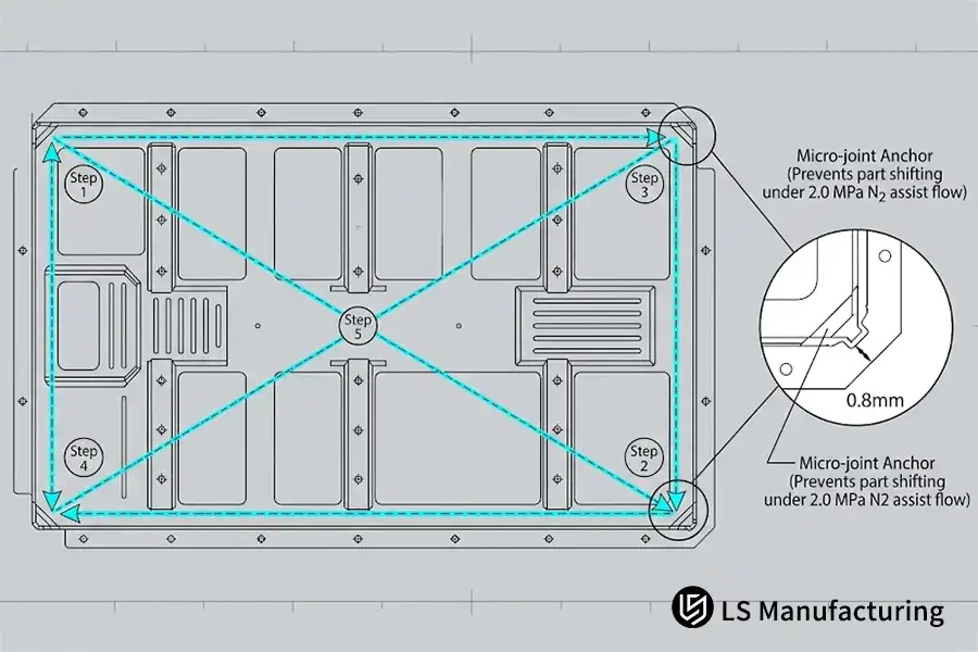
Figure 3: Optimized leapfrog cutting sequence (Steps 1–5) and 0.8 mm micro-joint anchor design on an EV tray frame, mitigating thermal distortion under 2.0 MPa nitrogen assist flow.
Which Materials and Profiles Are Most Suitable for Laser Cutting?
Fiber laser cutting is ideal for 1.5 mm–4.0 mm stamping sheet and extruded profiles. A 1.06 μm beam melts 6061-T6 and 6082-T6 structurals with burr-free edges at Ra 3.2 μm, ensuring solid bonding for structural adhesives. Evaluating overall laser cutting advantages and disadvantages helps engineers balance fast, flexible contours against thermal limitations on ultra-thick plate.
Material Grade Compatibility
- 6061-T6 Sheet (1.5 mm): Cuts quickly with straight, square edges.
- 6082-T6 Sheet (4.0 mm): Consistently yields an Ra 3.2 μm clean edge.
- 5182-O: Annealed temper cuts burr-free, but provides lower structural strength.
- Extrusions: Easily processed via specialized custom tube laser cutting setups.
Structural Sections Beyond the Laser Window
Four characteristics set fiber laser cutting apart from stamping and CNC milling of the aluminum tray structures.
| Attribute | Fiber laser cutting | Stamping or CNC milling |
| Suited gauge | 1.5 mm – 4.0 mm | Roughly triple the 4.0 mm ceiling |
| Typical stock | 6061-T6, 6082-T6 parent alloys | Cast plate |
| Edge finish | Ra 3.2 μm, burr-free | Sheared or milled edge |
| Typical use | Tray blanks, closures | Deep stepped grooves |
The initial fiber laser cutting tolerances also set the boundary: cast plates and deep stepped pockets are beyond the window as the beam focus and gas ejection diminish with increasing thickness EV battery housing laser cutting never punches through foam-cored laminates in one pass, as the trapped core gas expands faster than the plies transfer heat. The margin can be created with a go/no go gauge test below the 4.0 mm maximum.
The process depends on gauge grade, not material grade.
How Does Fiber Laser Cutting Control EV Tray Distortion?
Fiber laser cutting controls EV battery tray distortion by coordinating dynamic power modulation with a 1.6–2.0 MPa nitrogen assist flow to restrict the heat-affected zone (HAZ) below 0.08 mm. In a 2.5 mm 6061-T6 tray floor baseline, segmented pulsing distributes thermal loads across large-span cross-beam patterns, holding profile tolerances to ±0.03 mm without mechanical clamping deformation.
Application Scenario
Chassis program for new-energy commercial vehicles is 6061-T6 tray floor having large span with long round pattern and cross-beam bore pattern. Walls of perimeter seal groove should be machined perfectly and contour bands should be tightly fit before robot laser welding and gasket laying. Some engineering apprentices have been wondering whether most of the fixtureless cutting can maintain the bands without secondary machining process.
Rationale Behind Selected Parameters
Segmented pulse piercing (by "steering" pulses to make pauses between shots to allow the heat to escape) distributes the thermal load, while continuous piercing uses the energy of pulse in one point of time and space. The pressure of nitrogen assistance of 1.6–2.0 MPa controls the slag removal and turbulence in melt film and kerf; the greater the pressure, the wider kerf becomes. For non-segmented pulse piercing, heat affected zone (HAZ) is more than 0.08 mm, which exceeds the flatness tolerance for sealed tray floor.
Measured Results
Scrap rate was reduced from 14.5% to 4.2% during prototype runs, and the manufacturing cost for formed parts decreased by 11.8%. Beam heat delivery and assist-gas alignment contributed to scrap reduction during laser cutting of sealed tray floors; to sum up, thermal control affects flatness.
Data source: LS Manufacturing 2025–2026 internal test database (Project #AUTO-2026-T82, sample size >800, prototype tray floor runs).
FAQs
1. What is the essential difference between fiber laser cutting and the punch motion of EV tray?
Evaluating fiber laser vs mechanical cutting reveals fundamental processing differences: laser cutting is a non-contact thermal process that melts metal using a focused beam, while mechanical punching separates sheet material by shearing it between a punch and a die. Following ISO 9013:2017 thermal-cut tolerance classes, LS Manufacturing maintains edge profile tolerances between 0.01 mm and 0.05 mm for prototyping and small-batch validation. Junior engineers distinguish thermal cut edges from sheared edges before selecting dies for a tray program.
2. Why is nitrogen used instead of oxygen in the laser cutting of aluminum battery enclosures?
The assist gas is a coaxial flow that surrounds a cutting beam; nitrogen remains inert while oxygen undergoes exothermic reaction with molten aluminum and creates black oxide. From ASM Handbook Vol. 16 on thermal cutting, nitrogen at 1.6 MPa to 2.0 MPa blows out dross and results in Ra 3.2 μm face ready for gasket sealing. The LS Manufacturing welding preparation process maintains cut faces without oxide; purchasing personnel use one cut-face image to make judgment.
3. Can fiber laser cutting achieve machining tolerances below ±0.01 mm on battery trays?
No. Because fiber laser cutting is an inherently thermal process, dynamic factors—including thermal expansion of aluminum, machine guide clearance, and optical beam divergence—establish a realistic precision boundary of ±0.03 mm to ±0.05 mm under ISO 2768-m. While kerf width compensation reliably stabilizes profile repeatability, features demanding sub-±0.01 mm accuracy (such as coolant O-ring grooves or precision dowel pin holes) must be blanked by laser and finished via secondary CNC milling.
4. What design features should beginner engineers avoid in laser-cut sheet metal trays?
Micro-holes are bores smaller than the parent sheet gauge; over-concentrated beam energy over-melts bore walls ahead of assist gas clearing molten metal. Tab-and-slot features in laser cutting require slot width approaching parent sheet gauge, based on ASME Y14.5-2018 profile callouts. In other words, LS Manufacturing maintains a minimum 1.5 sheet gauges away from cut edges for narrow slots; junior engineers learn minimum bores early.
Summary
Once those assemblies material weight targets and file and beam layouts are finalized, and once the beam energy and assist-gas flow interactions and linear assembly tolerance zones are all settled at the design stage, all of those trade-offs begin to look tempting. Now leak-tight pack sealing becomes a matter of one repeatable process window, not grinding after the cut. In plain English: dwell heat and nitrogen ejection determine the tray flatness, long before fixtures show up.
EV Battery Structural Engineering & Technical Support
Understanding thermal cutting dynamics is the foundation of robust EV battery enclosure design. To evaluate downstream process trade-offs and structural tolerancing, explore our technical guides:
Related Reads: Guide to Custom Sheet Metal Fabrication: Select Fiber Laser Cutting vs. Waterjet.

