 English



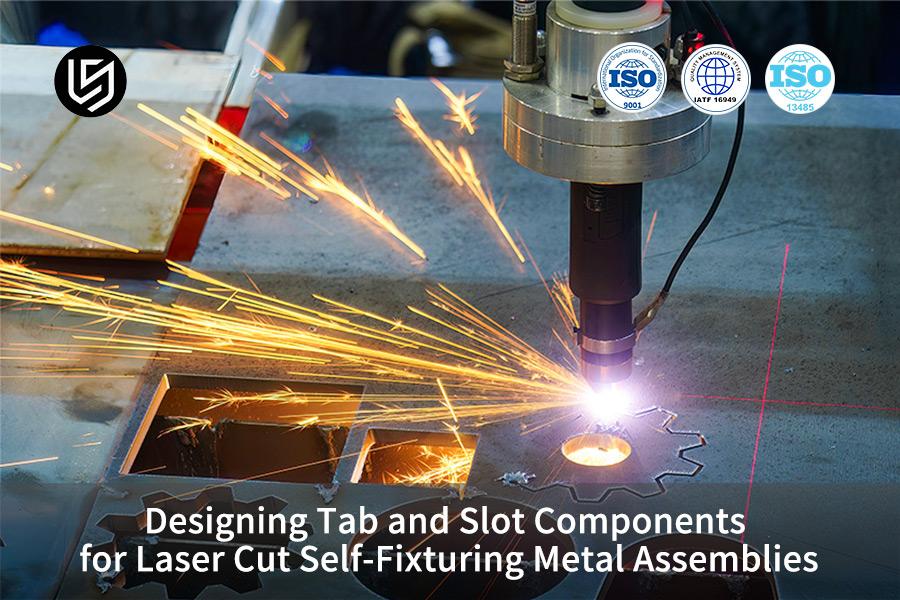
Tab and Slot Components Design is a core DFM optimization technique that reduces manufacturing process costs by eliminating welding fixtures. Unfortunately, because of the kerf between 0.1 mm and 0.3 mm and a cross-sectional taper of 1° to 3° resulting from laser cutting, using the exact CAD sizes without adjustment can create problems such as assembly looseness or interference cracking.
If the goal is to assemble high-strength parts without errors and without the use of joining fixtures, a detailed analysis of the proportion of material removal, the distribution of residual stress in the laser heat-affected zone, and the tolerance matrix of the tab is necessary. This guide will introduce you to the essential quantified core DFM design parameters and the process compensation standards.
Quick Overview of Core Parameters for Tab and Slot Component Design
| Design Dimensions | Key Parameters | Process Performance | Customer Benefits |
| Matching Gap | Single Side 0.05-0.1mm + Cutting Offset Compensation | Moderate Assembly Tightness, No Interference | Eliminates Secondary Repair Time |
| Corner Stress Release | R ≥ 0.5mm Dog Bone or Inner Recess | Eliminates Right-Angle Shear Stress Concentration | Reduces Load-Bearing Cracking Rate to Below 0.5% |
| Thick Plate Spacing | Slot Center Distance 8t-12t | Blocks HAZ Thermal Stress Overlap | Flatness Controlled Within 0.1mm |
Key Conclusions
- Matching Gap Standard: The precision single-sided material gap must be accurately controlled within the range of 0.05 mm to 0.1 mm, and single-sided offset compensation should be performed in the CAD features based on the laser beam cutting kerf.
- Eliminating Stress Interference: Getting rid of traditional right-angle slots, we have comprehensively adopted dog-bone or inward-recessed groove structures with a radius of R≥0.5 mm to effectively eliminate assembly interference and also release local shear stress.
- Thick Plate Deformation Prevention Ratio: For thick structural components with a thickness of 6 mm or more, the slot center distance must be per the material thickness ratio of 8t to 12t to prevent flatness distortion resulting from the accumulation of dense laser heat.
Why Trust The Precision Fit Of LS Manufacturing's Laser Cutting Component Design Service?
Our hands-on involvement in a project using a 304 stainless steel hydraulic pump valve bracket for a heavy mining machinery OEM revealed that traditional single-piece welding depended heavily on elaborate spot welding fixtures, with each fixture costing as much as $4,500 the assembly and debugging cycle reaching up to 18 days, and the first-pass yield being below 72% at the best of times. Laser cutting component design service essentially means using data instead of trial and error as a decision-making tool.
ISO 9013:2018 Thermal cutting, Classification and dimensional tolerances states in no uncertain terms that the profile tolerances for precision thermal cutting should correspond to the limits of the thickness grade, and kerf taper should be one of the acceptance parameters.
To comply fully with the standard, we changed the DFM (Digital Facing) concept in this project: 0.08mm precision clearance compensation on one side, 30° guiding chamfer, and a T-shaped self-locking lug geometry design, which altogether perfectly counteracted the laser kerf and sectional taper. The resulting product was 100% fixture-free self-positioning assembly that reduced pre-welding assembly time from 25 minutes per piece to 3 minutes, increased the first-pass yield from 72% to 99.4%, saved the customer 3 sets of dedicated fixtures, and cut overall tooling costs by 35%.
Accurate calculation of laser kerf compensation and sectional taper is the first hurdle to achieving fixture-free self-positioning assembly. Want to know if your design can achieve fixture-free assembly? Contact an engineer to obtain a Tab & Slot DFM Self-Checklist, including a gap calculation template and recommended dog bone dimensions to facilitate your optimization.

Why Does Standard Laser Cutting Kerf Distortion Cause Your Self-Fixturing Tab Slot Clearance Design To Fail On The Shop Floor?
Laser cutting with a 0.1 mm to 0.3 mm kerf and cross-sectional taper can result in loose fits or severe assembly interference in connectors due to the mismatch of parts and spaces. In this case, reverse tolerance compensation is required during CAD modeling. Essentially, tab slot clearance design becomes successful only if the kerf is considered a variable and not a constant.
Kerf Compensation Formula and Material Differences
When using high-power fiber lasers, kerf variation characteristics differ between materials. The main tool of DFM laser cutting service is the physical compensation formula.
- Single-sided slot width adjustment: Wslot = Ttab + 2×Kerfoffset - Ttaper, where Kerfoffset is defined as the material type. For instance, the Kerfoffset for 2mm aluminum sheet is 0.06mm, whereas for 6mm carbon steel it is 0.15mm, which is a notable difference.
- 2mm stainless steel: kerf width 0.15mm, taper 1.5°, 0.08mm single-sided compensation.
- 6mm carbon steel: kerf width 0.25mm, taper 2.5°, 0.15mm single-sided compensation.
Comparison of Pull-out Force under Three Compensation Options
We did a comparison using a pair of 2mm SUS304 connectors. The assembly performance of the custom laser tab slots parts with completely depends on the accuracy of compensation.The consistency of the kerf from high power laser cutting directly affects the batch assembly effect:
| Compensation Status | Single-sided Gap | Assembly Feel | Pull-out Force (N) | Rework Required |
| Uncompensated | 0.25mm | Looseness and wobbling | 45 | Yes, weld filling |
| Overcompensated | -0.05mm | Unable to fit | 0 | Yes, groove widening treatment |
| LS Manufacturing Precise Compensation | 0.08mm | Smooth insertion | 280 | No, direct welding |
Self-fixturing metal assembly reliability is mainly decided at the CAD phase. It may be interesting to consider that during mass production, metal sheet batch fluctuations can cause kerf differences of ±0.02mm. Because of this, it is recommended to include a safety margin factor in the compensation formula.
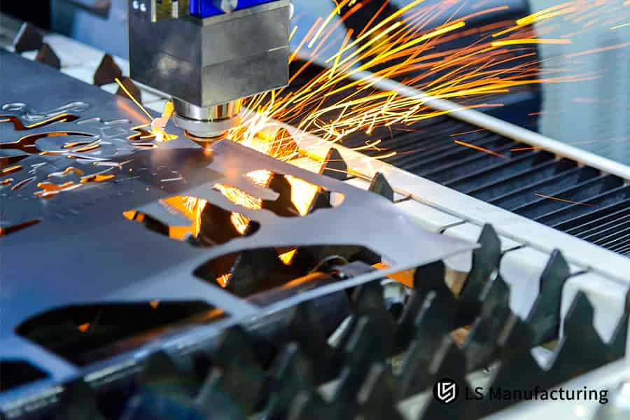
Figure 1: CNC laser cutting machine processing metal sheet with sparks flying.
How To Calculate The Optimal Material Thickness Ratio For Heavy-Duty Structural Custom Laser Tab Slot Parts?
For medium-thick plates with a thickness ≥3 mm, the lug height has to be within 0.5t and 0.75t. Increasing the lug height beyond these limits will result in a longitudinal distortion caused by the welding thermal stress. Designing thick plates for custom laser tab slot parts is a matter of accurately controlling the proportions.
Lug Ratio and Thermal Deformation Relationship
During the bottom layer welding of medium-thick plates, thermal shear stress is generated due to the different coefficients of thermal expansion, and the lug ratio directly affects the amount of deformation. The boundary conditions for tab and slot laser cutting design are as follows.
- Lugs protruding beyond the mating surface > 0.5mm: When there are no fixtures, the welding thermal stress results in a longitudinal distortion of 0.8mm. It is quite challenging to regain flatness even after a correction.
- Preserved root pass weld groove: Thermal deformation can be negated by plug welding, which can control distortion to 0.15mm.
- LS Manufacturing's measured data: When the lug ratio was reduced from 1.0t to 0.65t, the total assembly error was lowered from 0.8mm to 0.15mm. This change also led to less weld filler being used and a reduction in the total heat input.
Recommended values for lugs of different thicknesses
The application of self-fixturing metal assembly on thick plates requires the following parameters. The selection of fiber laser cutting parameters must match the material thickness:
| Sheet thickness | Recommended lug height | Slot center distance | Expected assembly error |
| 3mm | 1.8mm (0.6t) | 30mm (10t) | ±0.10mm |
| 6mm | 3.6mm (0.6t) | 60mm (10t) | ±0.15mm |
| 10mm | 5.5mm (0.55t) | 100mm (10t) | ±0.20mm |
Controlling laser cutting heat input is another key dimension to avoid deformation of thick plates. For plates thicker than 10mm, an additional stress-relieving annealing process is recommended.
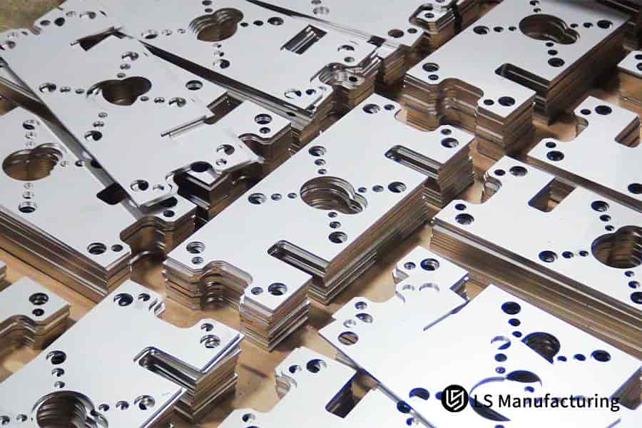
Figure 2: Stacked custom laser cut metal parts with various holes and slots.
How Do Dog-Bone Cutouts And Laser-Beam Taper Engineering Eradicate Internal Corner Stress Concentrations In Tab And Slot Laser Cutting Design?
Right-angle slots create a large amount of vertical shear stress on the underlying material. So, it is very important to add a right-angle internal relief groove or a dog-bone relief hole with the radius of the circular part at least 0.5 mm to get rid of assembly obstruction and avoid load-bearing cracking. the corner treatment in tab and slot laser cutting design is a deciding factor for the durability of the structural parts.
Laser Corner Overheating Mechanism
Laser beam slowdown at corners is the reason why overheating happens. Besides that, the tapered part results in the bottom of the connector getting shear stress damage. To get the result of optimizing the laser cut assembly fixture, first ask for the changes in the laser cutting beam focus at corners second perform three steps:
- Power Down 15%: Decreasing the laser power at the corner from 4kW to 3.4kW will prevent the corner from being overheated and melted. Also, the feed rate should be reduced by 10% at the same time to keep the quality of the cut.
- Make a 1.2mm diameter ear-shaped relief groove: It is necessary to put a dog-bone hole at the root of the right angle to lessen the stress concentration. The center of the dog-bone should be placed 1.5 times the plate thickness away from the vertex of the right angle.
- Lead in at 30° angle: At the outer end, make a lead-in structure to direct the assembly direction.
FEA Stress Comparison of Three Corner Designs
We compared the stress distribution of different corner structures using finite element analysis. Data from the laser cutting component design service is as follows. Laser cutting edge quality is most prone to degradation at corners:
| Corner Type | Maximum Stress (MPa) | Stress Concentration Factor | Fatigue Life (cycles) |
| Right Angle (No Treatment) | 385 | 3.2 | 12,000 |
| Right Angle + R1mm Rounded Corner | 260 | 2.1 | 38,000 |
| Dog-bone + R0.5mm | 185 | 1.5 | 65,000 |
In other words, a dog-bone shaped corner can increase the fatigue life of a corner by over 5 times. Laser cutting dross formation is also more likely to occur at corners, and the dog bone structure also improves slag removal. From our research, we suggest that the dog-bone layout should be made compulsory for all tab and slot parts that are exposed to cyclic loading.
Why Must Pitch Spacing And Micro-Joint Thermally-Induced Stress Be Dynamic Based On Your Chosen Manufacturing Materials?
Multiple tab and slot repetitions can generate high levels of heat. The slots' center-to-center distance should be between 8 and 12 times the thickness of the material to avoid overlapping heat-affected zones. The thermal handling of the tab and slot parts design should be reconfigurable based on the changes in material properties.
Thermal Stress Gradients of Various Materials
Materials with very high reflectivity and those with very low thermal conductivity show a huge difference in their thermal stress behavior during high-density laser cutting. The laser cut assembly fixture separation design should be different for these two kinds of materials. The intensity and pattern of the laser cutting residual stress depend quite a lot on the thermal conductivity of the material:
- 5052 Aluminum Alloy: It is a material with a high thermal conductivity level (137 W/mK), so the distance can be loosened to 8t. The residual stress is around 180 MPa.
- 304 Stainless Steel: Being a material with a low thermal conductivity level (16 W/mK), the distance should be increased to 12t, if not the residual stress will rise to 240 MPa.
- Result of slot spacing < 5t: Residual stress at the plate edge will be more than 240 MPa, and overall flatness will be more than 0.3 mm beyond the standard.
Dynamic Spacing and Bridge Width Matrix Table
DFM laser cutting service recommends the following parameters for different material thicknesses.
| Material | Thickness | Minimum Slot Spacing | Recommended Bridge Width | Expected Flatness |
| 5052 Aluminum | 1.5mm | 12mm (8t) | 0.8mm | ≤ 0.08mm |
| 5052 Aluminum | 3.0mm | 24mm (8t) | 1.2mm | ≤ 0.10mm |
| 304 Stainless Steel | 1.5mm | 18mm (12t) | 0.6mm | ≤ 0.06mm |
| 304 Stainless Steel | 3.0mm | 36mm (12t) | 1.0mm | ≤ 0.08mm |
| Carbon Steel | 6.0mm | 54mm (9t) | 1.5mm | ≤ 0.15mm |
The pressure selection of the laser cutting assist gas also affects the heat input, thereby altering the stress distribution. For highly reflective materials such as aluminum, using nitrogen assistance can reduce oxidation heat release, further reducing thermal stress.
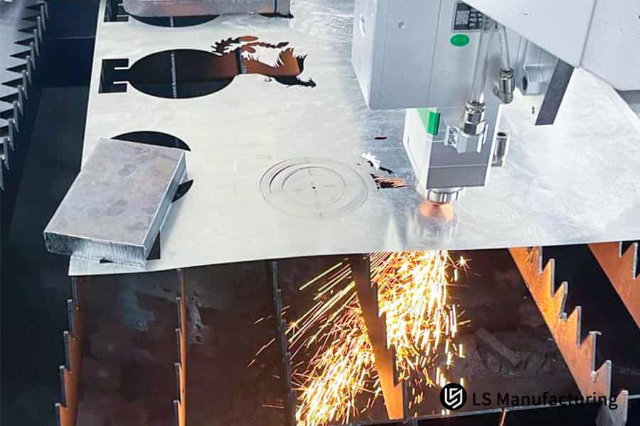
Figure 3: CNC punching machine processing sheet metal with various hole patterns.
How To Select The Proper Tab End-Style Geometry Between Sliding Clearance Fits And High-Strength Mechanical Press-Fits?
Clearance fits call for a 0.1 mm to 0.2 mm allowance on one side of the slot, whereas with interference fits, the slot should be equal or less than the lug width by 0.05 mm. The holding force of the assembly depends on the end geometry choice of the tab slot clearance design.
Comparison of Holding Forces of Three Different End Shapes
One of the easiest ways to change the force holding the physical structure together is by altering the geometry of the lug end. Laser cutting presses fit demands extremely high accuracy in dimensions. The fit design of the custom laser tab slot parts is below.
- Rounded End: Sliding fit, 0.15 mm clearance on one side, pull-out force 120 N, suitable for maintenance covers that need to be removed.
- T-shaped Locking Structure: Achieves self-locking in non-powered assemblies, pull-out force 450 N, suitable for permanent structural parts.
- Bidirectional wedge end: Interference fit, groove width 0.05mm smaller than lug, pull-out force 680N, suitable for high vibration environments.
Match Tolerance and Shear Force Comparison
The key to the success of interference fits lies in the dimensional accuracy of laser cutting.
ISO 286-2 Tolerances and Fits, Part 2: Selection of Tolerance Zones and Fits states: The choice of tolerance zones for interference fits should be following the material yield strength and the assembly method, the press-in force is to be determined separately for the extreme material conditions.
To follow this standard very strictly, in the press-fit design of T-type and wedge ends, we fixed the groove width tolerance zone at h7 and the lug width at s6. The recorded press-in force was 680N with a fit clearance of -0.05mm, and no plastic deformation of the base material occurred.
The end geometry directly determines the assembly holding force, sliding fits and interference fits each have their applicable boundaries. Unsure whether your connector should use a clearance fit or an interference fit? Download the Tab End-Style Selection Guide, which includes pull-out force curves and applicable scenario comparison tables for 6 end geometries.
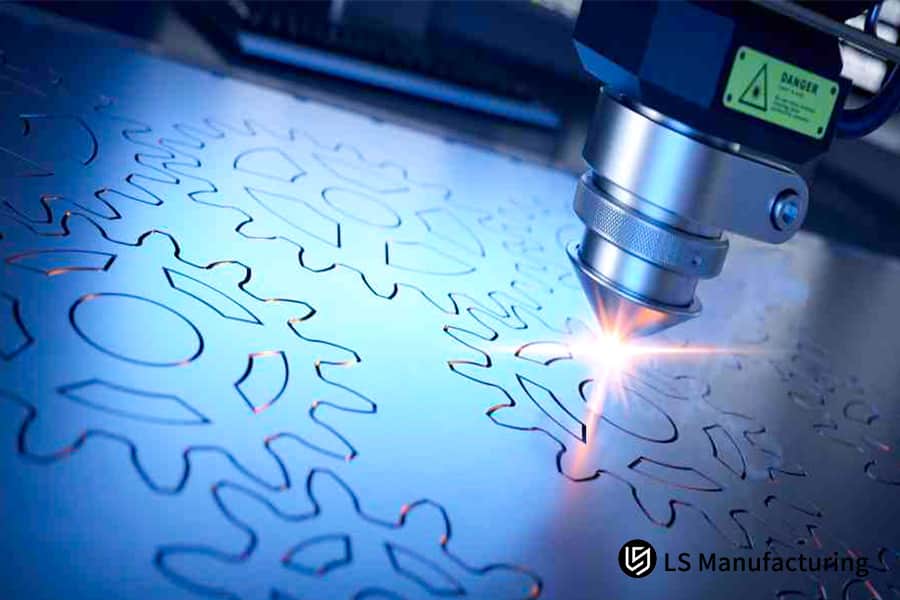
Figure 4: Precision machined parts with calipers and technical drawings.
Case Study: How LS Manufacturing Saved 35% In Welding Fixture Costs For An Industrial Mining Equipment OEM via DFM Laser Cutting Component Design Service?
Customer Challenges
One of the largest mining machinery Original Equipment Manufacturers (OEM) was modifying 304-grade stainless steel hydraulic pump valve bracket assemblies for high power applications in large batches. The conventional single-piece welding method included complex spot welding fixtures, with each fixture costing $4,500 and the assembly and debugging processes taking up to 18 days. The finished product frequently underwent twisting and deformation during welding thermal stress, which resulted in an overall assembly first-pass yield of less than 72%. The introduction of a laser cutting assembly solution was a game changer.
LS Manufacturing Solution
After LS Manufacturing intervened, the DFM solution for this component was restructured. The core modifications to the DFM laser cutting service included:
- Complete Self-Positioning Insertion Structure: The old two-piece structure has been improved to a self-fixturing tab and slot system, in which a 0.08mm precision clearance compensation is introduced on one side. At the same time, the original 12 parts, which were independent of each other, are combined into 4 self-positioning parts.
- Door frame chamfer guided by 30° + T-type self-locking lug: The perfect alignment of laser cutting and cross-sectional taper achieves a rigid self-locking. After three rounds of trial molding optimization, the T-type lug was ultimately able to exert a locking force 1.3 times the design requirement.
- Dog-Bone Release Hole + Dynamic Thermal Balance Scanning Path: In corner areas, thermal stress is concentrated and release holes with a diameter of 1.5 mm are made to help reduce the residual stress at the cut edge by 45%.
Results and Value
This approach results in 100% fixture-free, self-positioning, rapid assembly. The mass production figures for laser tab slot parts freshly customized are listed below. Higher laser cutting production efficiency automatically reflects cost savings:
- Welding pre-assembly time: has been slashed from 25 minutes/piece to only 3 minutes/piece.
- First-pass yield rate: has been boosted from 72% to 99.4%.
- Getting rid of 3 dedicated sets of fixtures leads to a 35% reduction in total tooling costs.
- Reduces delivery time by 60%.
Is your project also facing high welding fixture costs? Upload your 3D CAD drawings (STEP/IGS/DXF) and receive a free DFM assessment and accurate quote within 24 hours. Replicate this success story.
Why Choose LS Manufacturing As Your Trusted Partner For High-Precision Custom Laser Tab Slot Parts Production?
LS Manufacturing is your one-stop closed-loop processing and manufacturing service provider, from the very beginning of optimizing drawings to delivering large volumes. This is made possible by its full range of imported 12kW to 20kW super-power intelligent fiber laser systems, strict IATF 16949 quality management system, and group of highly skilled DFM specialists. The standard for delivery in laser cutting component design service is tolerance performance consistency 0.05mm.
Hardware Strength and Quality Assurance
The entire factory is equipped with Bystronic and Trumpf laser cutting machines, and features a 24-hour fully automated light-out production line. High-volume delivery of tab and slot component designs relies on the following capabilities.
- 100% live online laser interference monitoring: make sure the tolerance consistency of tens of thousands of connectors remains stable at 0.05mm.
- SPC/CPK Quality Data Reports: And each batch, detailed SPC control charts and CPK data streams are supplied.
- 15+ Years of Experienced Engineering Team: Complimentary DFM manufacturability review of drawings, fixing optimal tolerances and cost ratios at the source.
Certifications and Compliance
- IATF 16949 Automotive Quality System Certification: Traceability capabilities of automotive grade, able to manufacture components with safety-critical requirements.
- ISO 9001 International Quality System Certification: Standardized management system throughout the entire process, ensuring consistent delivery.
Stable mass production of self-fixturing metal assembly can't be separated from the hardware capabilities and process knowledge of a supplier. We provide a personal project manager for each of our strategic clients to make sure the communication is fault-free and immediate.
Ready to put your connector design into mass production? Contact our engineers for a free DFM assessment and SPC quality sample report. Verify before ordering, starting your collaboration with zero risk.
FAQs
Q1: What is the best gap clearance for a standard laser-cut tab and slot joint?
For standard stainless steel and carbon steel sheets with thicknesses between 1.5mm and 3.0mm, the precision design gap on one side of the tab and slot joint should be controlled at 0.05mm to 0.1mm. This range makes manual assembly easy and comfortable. And, it can also help to improve the quality of the pulsed welding weld pool while avoiding the main production problems such as the loose assembly and the welding defects.
Q2: What measures do you take to ensure that structural aluminum plates do not bend or warp due to heat during dense slot laser cutting operations?
We break a continuous linear cutting path by using a dynamic interval skip cutting path, which components the cutting heat. Besides, we carefully stick to a safe slot center distance for sheet thicknesses equal to or more than 10t, thereby getting rid of the overlapped heat-affected zones due to multiple slot cuts that cause bending and warping deformation of aluminum plates.
Q3: What is the most important reason for not selecting generic online automated laser services for high-volume custom laser tab slot parts?
The problem with generic automated laser processing programs is that they cannot be adjusted to the grain orientation and thermal deformation characteristics of various sheet materials, so it is impossible to accurately compensate for cross-sectional taper. Our expert engineers perform manual DFM (Design for Manufacturing) auditing in combination with the inspection of the full-size finished product, which guarantees the self-positioning assembly accuracy of large-volume connectors and helps to limit the risk of mass production failures.
Q4: Can tab and slot design guidelines completely replace expensive mechanical welding and assembly fixtures?
Yes, In fact. Our parts can lock 100% rigidly in self-positioning before spot welding without the need for additional welding fixtures. The basis is our self-developed T-type locking and wedge-shaped interference fit structure. It can completely substitute the traditional positioning fixtures, which implies a substantial reduction of the high production costs occurring due to custom tooling, debugging, and amortization.
Q5: How does the laser beam cutting speed influence the dimensional accuracy of an internal slot corner?
Slowing down the laser beam at corners may result in energy accumulation and a melt pool that overheats and enlarges the hole, because of this affecting the dimensional accuracy of the slot negatively. Our smart laser machines are equipped with dynamic frequency modulation and power ramp control technology, which automatically cuts the power down to 15% at corners to closely follow the micro-geometric dimensions of the internal tool relief groove, so guaranteeing assembly accuracy.
Q6: Which are the main quality system certificates honored by LS Manufacturing in the field of manufacturing of safety-critical components?
Our entire production and plant system has been double certified to IATF 16949 automotive grade and ISO 9001 general quality system. We can make the arrangement for delivery of a full set of compliant documents for safety-critical components such as material certificates, CMM full-size inspection reports, and SPC quality control charts.
Q7: How do you deal with thickness variance issues of raw materials from steel mills when manufacturing tight tab and slot fits?
Original equipment steel normally has a thickness tolerance of 10%, which could Really impact the precision mating effect. Our solution is to design flexible spring fingers and interference groove structures within the slots, thereby making use of the material's slight plastic deformation in compensating for the thickness fluctuations, so that the clamping force and fitting accuracy of the parts during assembly are continually stabilized.
Q8: What is your typical RFQ quote turnaround time and minimum order quantity for specialized industrial laser cutting component design service?
Upon receiving 3D drawings in STEP, DXF, or other formats from customers, our competent engineering team can provide a free DFM feasibility study report and an accurate quote within 24 hours. Our capabilities range from single-piece sample manufacturing to the large-scale production of millions of pieces. We encourage users to upload drawings so that they can get quickly customized processing solutions and quotations.
Summary
A zero-defect laser connector component design should address the structural load-bearing capacity, thermal properties of materials, and laser processing technology limitations. In fixture-free welding production, accurately compensating for the kerf, stress relief structures at the corners, and the dynamic slot spacing tailored to the material form the basis. Overlooking such DFM parameters may result in tolerance deviations, assembly deformation, and excessively high rework costs.
Material property-based optimization of laser processing can be an expedient way to address the manufacturing hurdles and shorten the product turnaround time. For avoiding delivery problems caused by laser processing inaccuracies and thermal stress, you are requested to provide 3D drawings in STEP, IGES, or DXF formats. Our engineers will perform a free DFM feasibility study and provide you with an accurate quotation within 24 hours. We operate at the highest precision prototype stage all the way to IATF 16949 standard mass production, also the provision of dependable, tailor-made manufacturing solutions for various sheet metal laser interlocking processes.

📞Tel: +86 185 6675 9667
📧Email: info@lsrpf.com
🌐Website:https://lsrpf.com/
Disclaimer
The contents of this page are for informational purposes only.LS Manufacturing servicesThere are no representations or warranties, express or implied, as to the accuracy, completeness or validity of the information. It should not be inferred that a third-party supplier or manufacturer will provide performance parameters, geometric tolerances, specific design characteristics, material quality and type or workmanship through the LS Manufacturing network. It's the buyer's responsibility.Require partsquotation Identify specific requirements for these sections.Please contact us for more information.
LS Manufacturing Team
LS Manufacturing is an industry-leading company. Focus on custom manufacturing solutions. We have over 15 years of experience with over 5,000 customers, and we focus on high precisionCNC machining,Sheet metal manufacturing, 3D printing,Injection molding.Metal stamping,and other one-stop manufacturing services.
Our factory is equipped with over 100 state-of-the-art 5-axis machining centers, ISO 9001:2015 certified. We provide fast, efficient and high-quality manufacturing solutions to customers in more than 150 countries around the world. Whether it is small volume production or large-scale customization, we can meet your needs with the fastest delivery within 24 hours. choose LS Manufacturing. This means selection efficiency, quality and professionalism.
To learn more, visit our website:www.lsrpf.com
