English



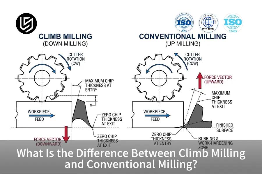
TL;DR: Climb milling refers to the subtraction process in which the cutter turns in the same direction of the feed, resulting in maximum chip thickness at the point of entry. The kinetic behavior increases structural stability of thin-walled structures, avoids rubbing of the tool, and ensures precision within tolerances of ±0.008 mm.
In the case of junior manufacturing engineers and procurement apprentices, choosing between climb milling and conventional milling may present a challenging task during the first review of drawings. In general, making the right choice regarding the rotation direction determines if the edge cuts pull the workpiece into the table or lift the piece into tool chatter. This guide presents 4 fundamentals of kinetic theory, along with the mechanics comparison table, in order to simplify chip creation and deflection vector analysis, as well as machine backlash.
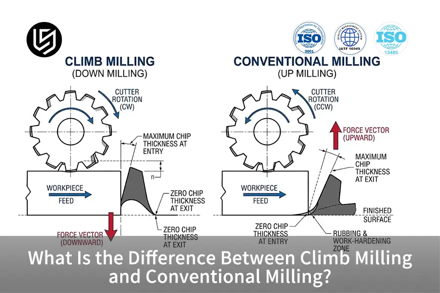
Key Takeaways
- Climb milling uses maximum chip thickness: The tool tooth cuts from maximum initial chip thickness to nothing at the end of the cut, removing any pre-shear burnishing and leaving surfaces smooth to Ra 0.8 µm.
- Conventional milling uses initial edge sliding: The cutting tooth contacts the metal surface with zero chip thickness, work-hardening the metal before any actual shearing takes place, thus producing higher local temperature.
- Force vectors control structural integrity: Climb milling produces downward forces that press components to their fixtures, while conventional milling produces upward forces that can lift the components.
- Machine backlash determines physical limits: Conventional milling is absolutely necessary when working with old manual machines that lack backlash eliminator because of the danger of table collapse and cutter breakage.
A Note from LS Manufacturing Engineers
This exhaustive engineering guidebook was written by Gloria Wu, who is the Rapid Prototyping and Rapid Manufacturing Expert of LS Manufacturing and has more than 15 years of experience in precision manufacturing. Gloria Wu can be followed on LinkedIn to receive technical updates on topics such as cutting mechanics and design for manufacturability. Each vector of kinetic force, chip thinning theory, and spindle backlash limit presented in this guide has been subjected to thorough peer review by the Chief Machining Engineering Desk of LS Manufacturing, in accordance with ISO 2768-m and ISO 2768-f standards of geometry and basic cutting principles from Machinery's Handbook, 30th Edition.
What Is Climb Milling and How Does It Cut?
Down Milling or Climb Milling
Climb milling or down milling denotes the basic cutting technique that is associated with a rotation direction of the spindle which is the same as that of the table feed direction. The key feature of its kinematics lies in instantaneous cutting at maximum thickness, subsequently decreasing until becoming zero when leaving the material. The described process results in eliminating of the sliding contact; therefore, the major tool forces act vertically downward onto the machine bed and lead to surface roughness from Ra 0.8 μm to Ra 1.6 μm.
Tool Kinematics in Modern CNC
During the conventional climb cut, the cutter tooth contacts the stock material above the centerline (when using the down-milling configuration) and removes it toward the finished floor. Since the cutting edge does not slide on the previously cut surface, but bites right into the uncut bulk metal, the mechanical shock load occurs when the tooth is fully supported. Based on the definitions of kinematics, the coinciding feed and rotational vectors concentrate instantaneous shear stress in the primary shear region.
Chip Formation from Thick to Thin
In contrast to abrasive grinding, the formation of chips in climb milling proceeds along a predetermined gradient of thinning. In the process, the chip emerges thickest at its inception and departs as a razor-thin ribbon at its exit. Thinning in this manner ensures that the quantity of heat generated during the process does not dissipate into the workpiece, since the vast majority of the heat dissipation occurs within the chip itself. As a result, workpiece thermal expansion is minimal, ensuring part tolerances of ±0.02 mm.
What Is Conventional Milling in Machining?
Traditional milling, traditionally termed up-milling, is a form of subtractive manufacturing process wherein the rotation of the cutting teeth is in direct opposition to the feed movement of the workpiece. The kinematics of this process is characterized by an initial chip thickness equal to zero and increases continuously to its maximum value just before the tooth disengages. This process tends to produce relatively rough surfaces due to rubbing, with values from Ra 3.2 μm to Ra 6.3 μm, although there are instances where it is appropriate for machining raw castings or for non-rigid setups.
- Initial Friction & Rubbing Phase: In the early stages of engagement, the cutting edge will not be able to penetrate into the parent metal. Instead, it will have to rub against the material until radial cutting forces can overcome the yield strength of the workpiece material.
- Work-Hardening Formation: The high burnishing pressures during initial rubbing generate localized heat. This effect is much more pronounced for machining austenitic stainless steels or high-temperature alloys, resulting in a skin layer that dulls the carbide flutes during the following cut.
- Vectors of Upward Dynamic Forces: Since the tooth picks up material from the bottom of the cut, the vector of forces acts vertically upwards and away from the holding fixture, thus increasing the force margin needed to clamp the workpiece.
- Functional Zone of Application: Even though there is higher friction, regular milling is very effective in working on structural steel pieces with hot rolled scales, sand castings, or flame cut pieces. The tool bites into clean and soft base metal beneath the hardened and abrasive surface and pops out through the surface without touching the brittle carbide cutting edge.
Which Milling Direction Ensures Better Accuracy?
Within strict CNC milling settings, climb milling always yields better dimensional accuracy and tolerances when compared to conventional milling. The downward force vector in climb milling helps fix the workpiece tightly against the datum of the reference fixture, reducing any chatter amplitude dynamically. As a result, current 3-axis and 5-axis machines can easily hold general tolerances at ±0.02 mm within ISO 2768-m, while reaching ±0.008 mm within ISO 2768-f. On the other hand, conventional milling causes small deflections, pulling flexible workpieces away from the datum, resulting in dimensional variation between ±0.05 mm and greater values.
The following comparison explains the mechanical differences between both milling techniques:
|
Dynamic Comparison Metric |
Climb Milling (Down) |
Conventional Milling (Up) |
Physical Mechanism & Impact |
|
Chip Thickness Gradient |
Maximum at entry → Zero at exit |
Zero at entry → Maximum at exit |
Climb eliminates edge rubbing, suppressing strain-hardening in alloys. |
|
Resultant Force Direction |
Downward onto fixture & bed |
Upward pulling part away from table |
Climb stabilizes thin floors; conventional requires heavy clamp margins. |
|
Surface Finish Capability |
Ra 0.8 μm to Ra 1.6 μm |
Ra 3.2 μm to Ra 6.3 μm |
Climb prevents recutting of chips, preventing secondary marring. |
|
Backlash Sensitivity |
Critical; requires anti-backlash nut |
Low; table feed resists cutting motion |
Climb pulls loose tables into cuts; conventional safely dampens screw play. |
As is seen from the above data, climb milling is undoubtedly the right solution for achieving high precision surface finish and accurate dimensional machining on modern rigid CNC machines. However, conventional milling should be considered as an important option when working with rough castings and machining using machines without mechanical backlash correction.
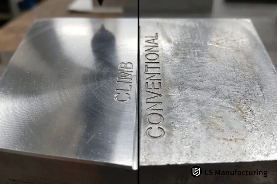
Figure 1: Microscopic surface finish inspection showing a uniform Ra 0.8 μm mirror finish from climb milling compared to cloudy rubbing marks from conventional milling.
Why Is Climb Milling Suitable for Machining Thin Wall Parts?
When working with unsupported areas, such as ribs less than 1.5 mm thick or housing pockets, climb milling is an indispensable feature of design for manufacturing. The cutting force resulting from it acts downward on the part, thus allowing keeping predictable and parallel radial tool pushes against the bottom of the workpiece. Together with high cutting speed and small stepover, this technique prevents harmonic vibrations, maintaining a tolerance in ±0.01 mm without structural deflections.
Engineering Desk Perspective: Deflection of Walls
"In machining deep aerospace pockets with high aspect ratio walls, the upward cutting forces tend to deflect the unsupported wall away from the cutter leading to pronounced wall taper and chatter lines. With LS Manufacturing, we follow CNC programming rules to use climb milling and light radial depth of cut (ae ≤ 0.10 x tool diameter). This force vector keeps the fragile aluminum flanges firmly on the base plate instead of pulling them into the flutes."
— Gloria Wu, Rapid Manufacturing Specialist
Climb milling is the only way out for achieving good thin walls in practical applications such as robot joint linkages, medical device enclosure cases, and battery trays. The downward force helps minimize vibrations and enables end mills to cut ductile aluminum alloys smoothly without causing any damage to the structural walls."
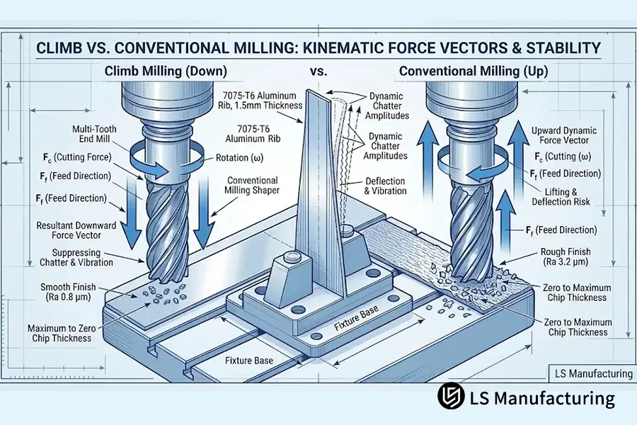
Figure 2: Downward resultant force vectors in climb milling actively clamp tall 1.5 mm aluminum ribs against fixture datums, eliminating thin-wall deflection.
Why Does Machine Backlash Threaten Climb Milling?
Backlash, which is the space between the lead screw and drive nut, is one of the most serious hazards involved in climb milling. In climb milling, the cutter flutes actually suck the work piece in the direction of the feed motion of the table. In a machine slide with a mechanical backlash greater than 0.05 mm, the cutting force will push the machine table into the cutter and eliminate the space between the screw and the drive nut instantly. This will cause an uncontrollable sudden motion that will cause the cutter to dig an oversized bite in the material and stall the spindle or break the carbide flutes.
Common Engineering Fallacies
- The Fallacy: "Climb milling is always better and must be used on all machines regardless of their vintage."
- The Fact: Climb milling is very dangerous when not performed using a backlash elimination device or preloaded recirculating ball screws.
- The Physics Behind It All: With traditional up-milling, the cutting force resists the feed direction, putting the nut in intimate contact with the screw threads and thereby eliminating any slack. With climb down-milling, the cutter draws the screw through the clearance between threads, causing abrupt and uncontrollable movement of the table.
With modern CNC machine centers, two preloaded ball nuts and linear optical scales have been employed to solve this problem and make climb milling possible. However, for old shop machinery and manual milling machines, it is always safer to employ conventional milling techniques.
How Climb Milling Works in Practice: A Robotic Arm Example from LS Manufacturing
During the pre-production manufacturing of the swing bracket out of 7075-T651 aluminum with wall thickness of 1.5 mm including a center bearing with a bore size of ±0.008 mm for 6-axis collaborative robotic arm, the initial trials of milling paths in a combination led to chatter marks around the thin walls. Initial surface finish was determined as Ra 3.2 μm, which did not comply with the sealing interface requirements.
At LS Manufacturing engineering department, they redesigned the toolpaths, using only the climb-milling finish strategy. According to the cutting speed and feed recommendations from tool dynamics for cutting tool standards, they set cutting speed Vc = 150 m/min, with feed per tooth fz = 0.08 mm/tooth, axial depth ap = 3.0 mm, and radial width ae = 0.25 mm. The cutting parameters guaranteed that the tool would cut at full chip thickness and not slide over the strain-hardened aluminum alloy 7075.
With respect to the optimized climb milling approach, the surface finish was enhanced to Ra 0.8 µm whereas the critical bore diameter remained within the specified ±0.008 mm tolerances range. On the run, batch part scrap rate reduced to 4.2% from 14.5%, costs of secondary deburring operations fell by 8.5%, and delivery cycle time was cut down by 12%. Thus, this case study proves that choosing the proper tool rotational vector significantly affects dimensional tolerances and finish of parts.
Source of Data: Case Study #ROBOT-2026-8842 (LS Manufacturing Machining Database, Sample size >800).
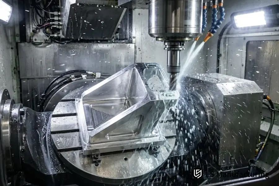
Figure 3: Dedicated 5-axis climb milling of a 7075-T651 aluminum robotic arm bracket held to ±0.008 mm precision under Project #ROBOT-2026-8842 at LS Manufacturing.
FAQs
Which is the primary difference between climb and conventional milling surfaces?
While the climb milling process creates a uniform and mirror-like surface with constant micro-cusps without any signs of burnishing lines, the conventional milling creates cloudy traces with irregular marks on the surface due to the initial sliding and rubbing phase of the milling tool.
Can novices engage in climb milling on a manual Bridgeport mill?
Novice machinists must not use climb milling on manual mills unless the machines are specially equipped with an anti-backlash ball screw nut. Manual mills without anti-backlash ball screw nut feature standard ACME lead screws, with their lead clearance, pulling the table into the cutting tool, thus creating high risks of breaking the cutting tools or injuring the operator.
Why does conventional milling cause additional heat on the cutting edge?
Since the tooth enters the material without any thickness, it abrades and burnsishes the base material prior to chip removal. Heat generated from mechanical work transforms into localized contact heat, remaining concentrated in the area of the tool tip, resulting in increased flank wear.
What milling strategies does LS Manufacturing apply to aerospace parts?
All rigid multi-axis aerospace parts machining setups at LS Manufacturing are programmed with dedicated climb milling cycles. Preload linear guides and high-pressure through-spindle coolant enable controlling cutting forces, allowing precise control of structural tolerances of ±0.08 mm (±0.008 mm on critical journals).
Conclusion
Understanding the distinctions between climb and conventional milling allows mechanical engineers and technical buyers to make more intelligent manufacturing choices well in advance of any actual cutting. Although climb milling provides a superior surface finish and precision machining on rigid CNC machines, conventional milling is still an important process when machining raw castings, scaling crusts, and manual machinery that isn't tightly secured. With LS Manufacturing, using these basic machining concepts under ISO 2768-m/f standards allows us to produce parts that have exact structural and functional tolerances every single time.
Kinematic Guidance & Application Engineering Support
Whether you're evaluating tolerance stacks, checking out thin wall deflections concerns on prototype prints, or verifying machinability vectors across different alloy grades, LS Manufacturing application engineers are always ready to help. You can check machining dynamics and manufacturability of your parts straight from the LS Manufacturing engineers by calling us at +86 185 6675 9667, technical correspondence at info@lsrpf.com, or visiting our engineering resource page at https://lsrpf.com/.
Related Resource: Precision CNC Milling For Thread Cutting Taps: Achieving High-Hardness Tooling Solutions