 English



TL;DR: RF enclosure CNC milling tolerances are dimensions within which computer numerical control (CNC) machining is performed on the housings for microwaves, ranging between ±0.005 mm and ±0.01 mm. Tool paths programmed in batches keep ±0.005 mm even after exceeding the general tolerances per ISO 2768-1:1989. Anything after ±0.01 mm results in a seam that allows RF energy leakage.
Junior procurement specialists and graduate mechanical engineers moving into RF hardware have the perception that all ±0.005 mm are universally required. Dimensions not specified fall under the default dimensional band, wherein most housing walls would never require ±0.005 mm. Two machining processes with an additional classification matrix are enough to take care of the geometric dimensioning, frequency operations, and inspection process points. RF hardware team knows where to apply the strict band and where to allow some room – Simply put, tighter doesn’t mean better shielding.
Key Takeaways
- Tolerance classification is associated with a functional requirement breakdown: critical geometric elements of the RF cavity’s internal core are specified according to precision tolerance ranges between ±0.005 mm and ±0.01 mm, whereas the outer mechanical frame of the component has standard tolerance ranges between ±0.01 mm and ±0.05 mm.
- Electromagnetic isolation is a key element in gap management for microwaves: the flatness of the surfaces being mated within the cavity housing flanges should be controlled at ≤0.01 mm to prevent small gaps that could serve as slot antenna sources emitting high-frequency signals (especially in the X and Ka frequency bands).
- Skin-effect losses depend on inner cavity roughness: the surfaces of the microwave resonator should have microscopic surface roughness of Ra (arithmetic average roughness, the standard surface finish unit in μm) 0.4 μm to Ra 0.8 μm to avoid losses due to the interaction of high-frequency currents and surface irregularities.
- Scientific tolerance designation facilitates cost reduction: according to the LS Manufacturing database, systematic exclusion of the use of the highest precision tolerance values throughout the whole drawing saves machining time and provides average optimization of manufacturing costs by 11%.
Why Trust This Beginner's Guide?
Gloria, senior rapid prototyping and manufacturing specialist at LS Manufacturing, has over 15+ years of CNC milling practice, specializing in 5-axis RF enclosure DFM reviews for X-band / Ka-band programs, and heads DFM reviews for high-frequency structural elements. Follow Gloria's engineering insights on LinkedIn for class notes on dimensional bands.
LS Manufacturing's head RF manufacturing engineering group analyzed each of the dimensional statements prior to publication. Validation with ASME Y14.5-2018 (Geometric Dimensioning & Tolerancing – GD&T code for feature control frames) relates flatness of flanges to the datums, making their mating surfaces to have a single measurement origin.
Data source: LS Manufacturing 2025–2026 RF housing test log (Project #AERO-2026-881, sample size >800). Roughness about Ra 0.6 μm of the cavity walls was measured according to ISO/IEC 17025:2017 (calibration-laboratory competence, making readings comparable between laboratories). Yearly review updates values till September 2026. Put simply, cavity walls get narrow bands; mounting flanges don't.
What Are CNC Milling Tolerances For RF Microwave Enclosures?
RF enclosure CNC milling tolerances are the size bands allowed for a microwave enclosure, with walls and flanges of the resonant cavities being maintained within ±0.005 mm to ±0.01 mm and the outer frame of the housing being within ±0.05 mm band. Each size band defines how much the milled wall can deviate from its original place without affecting electrical characteristics. Resonance frequency of the cavity is dependent on cavity width, as it defines both capacitance and inductance of the resonant cavity. Loose size bands will de-tune the cavity and allow energy to escape.
Each tolerance of an RF enclosure is an electrical tolerance in mechanical terms, as the position of a wall defines resonance frequency.
How CNC milling works sets the floor: thinner walls will flex, using more precise grades is simply wasting time since they don't affect resonance.
Engineers asking what is acceptable tolerance for microwave housing want one number, yet cavity walls and flanges need two.
For each linear size, ISO 286-1 (Geometrical product specifications - Code system for tolerances on linear sizes) provides an International Tolerance (IT) grade – an IT number corresponding to a deviation band. IT grades regulate sizes, whereas roughness grades like Ra 0.8 μm regulate texture.
- ±0.005 mm to ±0.01 mm (IT5 to IT7) for cavity walls
- ±0.01 mm to ±0.05 mm (IT8 to IT10) for connector seats
- ±0.1 mm and coarse (IT11+) by legacy convention, for mounting feet
Fine grades apply to cavity walls, coarse grades apply to mounting feet – distinction that every RF enclosure CNC machining guide must make clear.
What to Remember
- Tolerance bands are electrical limits translated into mechanical units
- ISO 286-1 IT grades identify each band
Source annotation: ISO 286-1 (Geometrical product specifications - Code system for tolerances on linear sizes).
Related keywords: RF enclosure CNC milling tolerances / microwave housing bands / milling tolerance grades

How Do CNC Machining Tolerances Affect EMI Shielding Effectiveness?
CNC milling tolerances for RF enclosures determine the EMC shielding of a microwave enclosure based on the gap that is left at each seam of the housing due to the fact that a gap close to a quarter wavelength acts like an aperture antenna rather than being electromagnetically sealed. EMI (electromagnetic interference, the energy exiting a circuit) leaves the housing through the seams; design of the seam determines the effectiveness of the shielding and not the accuracy of the parts. CNC milling tolerances for RF enclosures is defined by the following single principle: shielding is determined by joint geometry.
"In microwaves, a machining tolerance is more than a matter of fit. It is the geometry of the electromagnetic boundary conditions." — LS Manufacturing RF Manufacturing Laboratory
Slot Antenna Effect at Machined Seams
Slot antenna effect (radiation through an elongated opening in a conductive plane) tells us why there's still a leak even though the seam appears closed, and the name is important because it tells us leakage increases as wavelength decreases. The function of the seam determines the cut, RF enclosure CNC milling tolerances go by the flow of current instead of the shop's standard practice.
Current path sets the band:
- cavity joints at ±0.01 mm, cut against the suRFace current
- gasket grooves at ±0.01 mm, aligned with flange faces
- mounting feet at ±0.05 mm, not cut by current flow
Repeatability behind how CNC tolerances affect EMI shielding — cutting using a rotary tool running the same programmed path — allows one band to be produced repeatedly on many pieces. A 5-axis machining centre cuts all flange faces in one setup, while a 3-axis machine requires another setup.
Conductive Gasket Groove Depth and Flatness
Conductive elastomer gaskets (rubber seals conducting electricity which seal off the joint when compressed) have to be evenly compressed into a joint. Depth of the groove establishes the compression, so keeping the groove within the same ±0.01 mm range as the flange faces guarantees an even compression; any greater depth results in an under-compressed gasket which leaks.
Engineers looking for what is acceptable tolerance for microwave housing use the tightest band everywhere. Surface current only flows through the joint, so outer-frame tolerances add nothing to attenuation. One measurement will answer the question: measure flange flatness and groove depth at the joint, and keep everything else outside of the SuRFace current band in the wider tolerance. Selection of materials depends on the seam control, and CNC milling materials guide conductivity as more important than tensile strength for cavity walls.
Main Points
- Seam width determines shielding; wall thickness is irrelevant
- Groove depth and flange flatness fall in one band
Related keywords: CNC milling shielding tolerance / microwave housing seam tolerance / RF enclosure EMI bands

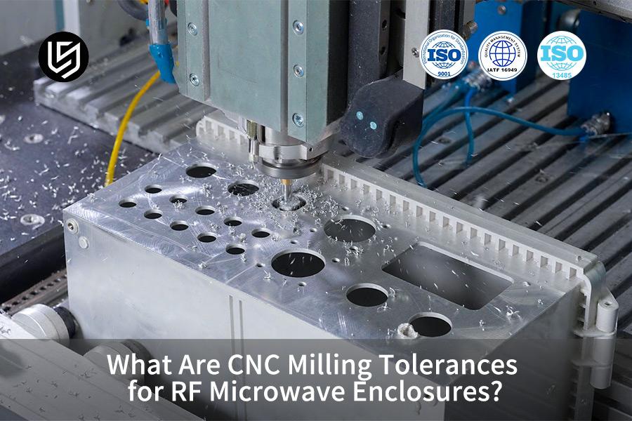
Figure 1: CNC milling clamps a 7075-T651 rf housing blank on one datum holding flange flatness at ≤0.01 mm.
Basic Comparison Table
Four engineering dimensions contrast precision-grade bands with standard-grade bands for one RF microwave enclosure. Wall purpose, electrical function, surface finish, and practical application define the point at which a resonant cavity ends and a mounting frame begins. Young engineers get a method to distinguish electrical dimensions from mechanical dimensions before analyzing a drawing.
| Engineering dimension | Precision tolerance ±0.005–±0.01 mm | Standard tolerance ±0.01–±0.05 mm | Traditional rough reference ±0.1 mm |
| Covered features | resonant filter cavity, partition knife-edge, coaxial blind hole | external mechanical mounting flange, heat sink fin profile | outer blind area, nameplate slotcut |
| Physical mechanism | supports electromagnetic resonance frequency and impedance continuity | provides housing structure rigidity and frame drilling match | only gives basic physical protection and dust exclusion |
| Surface roughness requirement | held at Ra 0.4–Ra 0.8 μm to reduce loss | maintained at Ra 1.6 μm for assembly fit | held at Ra 3.2 μm, no microscopic electrical demand |
| Typical industry application | satellite microwave circuit assembly, airborne radar front-end assembly | base station frame assembly for mobile, bottom housing for vehicle gateway | conventional industrial motor housing, civilian low-frequency junction box |
Precision tolerances at ±0.01 mm for internal microwave circuits and electromagnetic shielding, while normal tolerances of ±0.05 mm are used for assembly and weight reduction.
Why Does RF Cavity Resonance Require Exceptionally Tight Tolerances?
Why RF cavity resonance requires tight tolerances comes down to one relation: a cavity operates at a frequency determined by its three-dimensional dimensions, walls kept within ±0.005 mm to ±0.01 mm. Frequency of resonance is inversely proportional to cavity dimensions, implying that any alteration in dimensions will lead to an alteration in frequency of resonance. Milling chatter causes changes in resonance frequency. Floor and side walls need to have a Ra value between 0.4 μm and 0.8 μm. Textures create more resistance, RF enclosure surface roughness standards dimensional band with textures.
Skin Depth Against SuRFace Roughness
Skin depth (the point at which current density reduces to a minor fraction of its value at the surface) reduces with increasing frequency, thus making the current to flow through a thin layer in high frequency. Skin depth is sometimes confused with roughness height, where one represents current penetration and the other represents texture.
| Surface texture | Skin relation | Loss outcome | Typical location |
| Ra 0.4–Ra 0.8 μm | peaks stay under current layer | return loss stays compliant | cavity floor, side wall |
| Ra 1.6 μm | peaks reach current layer | peaks reach current layer insertion loss climbs | fixing flange, heat-sink base |
| Ra 3.2 μm | peaks break current layer | resonance damps, Q falls | outer cover, nameplate slot |
A difference between standard and tight tolerances RF is in the inspection area, where coordinate measuring must be used for cavity walls, but mount faces have to undergo just the height inspection. Limits of texture have the same classification.
Walls thinner than the tool diameter deform under cut pressure. CNC milling principles explain deflection gives stock and the displacement of the stock resonates. Simply put, cavity acts as an instrument, not a box.
Junior engineers tend to interpret each tight callout as general. Programmed operations repeat the single band per batch, and how CNC milling works depends on removing stock along the predetermined path.
Source: Machinery's Handbook, 30th edition, Chapter 28 (SuRFace Texture and Cavity Tolerancing).
Related keywords: RF cavity tolerance bands / microwave cavity roughness limits / resonance frequency CNC milling
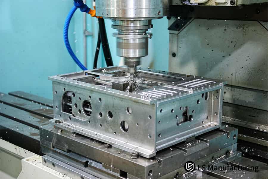
Figure 2: CNC milling forms 6061-T6 rf shielding box walls around a slot antenna seam at ±0.01 mm.
How Do Aluminum Alloys Impact CNC Milling Tolerances For RF Housings?
RF housing dimensions will be determined by aluminum alloys because thermal expansion and stresses release in thin walls determine the cut path. Aluminum expands twice as much as steel in each degree; cutting will distort its dimensions due to thermal expansion. 6061-T6 is alloyed to provide balance in machining and stability, while 7075-T651 (relief stress due to stretching) is used in ultra-thin cavity walls.Finishing operations take place at Vc=60 m/min (cutting speed). How aluminum alloys impact RF tolerances is exhibited as drift.
Source: ASM Handbook Volume 16: Machining (Parameters for Wrought Aluminum Alloys).
Residual stresses created in the process of rolling and heat treatment cause thin-wall distortion. Roughing opens up one side of the wall to make room for bending; annealing after roughing takes place. Thin ribs deflect in the cut process due to stress, springing back; forming stock, which is resisted by 7075-T651; 6061-T6 needs less cutting force.
Heat is the main factor of warpage, annealing process should be done prior to the finishing process. One difference between standard and tight tolerances RF: tight bands will be kept only when all the stresses will be removed, wide bands allow for movement. An RF enclosure CNC machining guide machine capabilities alone ignore the process.
All junior engineers think that precise positioning can help to avoid drifting. Measure the cavity depth after the finishing and the next day. To put it simply, the computer numerical control (CNC) ±0.01 mm band is achieved after heat and stress movement.
Points to Keep
- Residual Stress causes wall movement after tool removal
- Vc = 60 m/min finishing helps to avoid heat shift
Related keywords: aluminum alloy CNC milling tolerances / RF housing thin wall machining / CNC milling thermal drift
What Is The Difference Between Standard And Tight Tolerances In RF Parts?
The difference between standard and tight tolerances RF parts rests on machine class, inspection depth, and application limits. Standard tolerance range of ±0.01 mm to ±0.05 mm runs on a typical 3-axis vertical machining centre and works for housing outline. Tight tolerance range of ±0.005 mm to ±0.01 mm requires a thermally controlled 5-axis simultaneous centre, where a CMM (coordinate measuring machine, a probing device which measures feature against datums) checks all datum holes; CMM measurement results dictate qualification, hence the specified tolerance range defines inspection burden. Separation of the two ranges by function prevents over-machining throughout the process cycle. What is acceptable tolerance for microwave housing follows function, not habit.
Machine Class Behind Each Band
3-axis vertical machining center mills X, Y, and Z and holds standard bands on the housing.5-axis simultaneous machining center uses two extra rotary axes, whereby the same clamping is used for all five faces of the part, and repeat positioning errors are eliminated. CNC milling tolerance bands are controlled based on the machine category because CNC milling is done once per batch for each programmed path.
Inspection Depth Per Band
Standard bands can be inspected using a caliper or a height gauge test. However, tight bands must go through CMM inspection of datum holes in accordance with the Zeiss CMM Calibration & Verification Standard (ISO 10360 series), where ISO 10360 (Acceptance and reverification tests for coordinate measuring machines) sets the probe error tolerances. Probing is different from optical scanning.
Three Checks Before Marking a Callout
- Current path — cavity walls with surface current get a tight band; mounting feet have no current.
- Setup count — faces accessible through a single clamp setup receive a tight band; faces re-clamped lose datum continuity.
- Inspection load — a tight band requires full probing, RF enclosure CNC milling tolerances stop at the seam.
Many junior engineers interpret all tight callouts as universal. Surface current runs only across the seam, the outer frame dimensions offer no additional shielding; a single test resolves the issue – sketch the path of the surface current on the drawing, mark the faces with the current, and leave the other faces generous. CNC milling datum setup then determines if the tight band withstands re-clamping. Practically, a single path sketch solves all tight callouts.
What to Note
- Machine class sets the reachable band
- Tight bands force full probing
Related keywords: rf part tolerance bands / standard versus tight machining bands / CNC milling inspection depth
Figure 3: CNC milling cuts a 7075-T651 rf enclosure cavity under coolant mist holding ±0.005 mm for microwave housing resonance.
Decision tree
Wall thickness, dimensional band, and surface finish distinguish the one RF enclosure into distinct milling branches. Seam performance distinguishes cavity walls from mounting frames; therefore, the branching is based on quantifiable geometry. Junior engineers gain an ability to understand how to interpret RF enclosure CNC milling tolerance and decide which dimensions have surface currents flowing along them.
| Feature group | resonant cavity wall | knife-edge seam | mounting flange | outer non-mating face |
| Size envelope | ±0.005–±0.01 mm | ±0.005–±0.01 mm | ±0.01–±0.05 mm | ±0.1 mm |
| Physical role | sets resonance; keeps impedance | closes seam against slot radiation | holds frame rigidity | shields dust only |
| Surface finish | Ra 0.4–0.8 μm | Ra 0.4–0.8 μm | Ra 0.8 μm or coarser | no electrical demand |
| Typical use | satellite microwave channel | airborne radar combiner | base-station frame | industrial motor cover |
Cavity walls controlled within ±0.01 mm will be machined according to 5-axis single setup path with respect to ASME Y14.5-2018 datums.
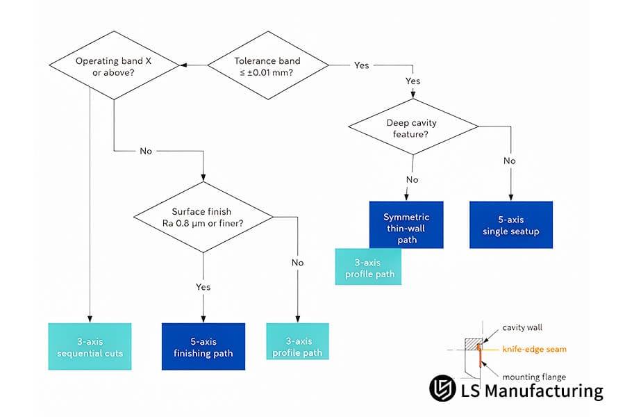
Figure 4: CNC milling RF enclosure 7075-T651 process path.
How Precision Milling Works In Practice: An Aerospace RF Shielding Example From LS Manufacturing
Graded dimensional bands are achieved through CNC milling in an RF shielding box since the cavity depth controls the resonance frequency and there is no surface current on the outer frames. In this case, the commercial aerospace industry designed a dual-cavity X-band converter shielding box, whereby each dimension had the finest band initially. Cavity depth and mating knife-edge dimensions have tolerances ranging from ±0.005 mm to ±0.01 mm, and the walls have Ra 0.6 μm. CNC milling cavity resonance tracks wall position, so graded bands protect filtering while wider bands absorb frame movement. X-band radar front ends and Ka-band satellite channels share one split rule.
Application Scenario
Commercial aerospace industry provides one example to teach about the application of tolerancing principles. A startup R&D team made a dual-cavity X-band converter shielding box, whereby each cavity was made using 7075-T651 pre-stretched aluminum plate. The partition seam had to have an airtight fit of ≤0.01 mm.
Principle in Practice
Finishing cutting was carried out at Vc = 60 m/min because there is residual stress in 7075-T651, which creates cutting heat as warp. Higher value raises the temperature, stress relief makes cavity depth exceed ±0.01 mm. Meanwhile, the lower value raises cutting force and deforms thin ribs.
Measured Results
Defect percentage decreased from 18.5% to 4.2%, and cost dropped by 11–12%. blanket tightness does not provide any protection since the surface currents pass only through seams. Diagram below depicts a mark along a current trace of CNC milling dimensional bands suitable for fine quality. In other words, the function indicates if the cavity has resonance or not, not the machine itself.
Data source: LS Manufacturing 2025–2026 RF housing test log (Project #AERO-2026-881, sample size >800), drawn from a 2025–2026 measured database holding more than 800 records.

FAQs
1. What is the acceptable tolerance for a microwave housing?
An acceptable tolerance for the microwave housing will be a range of sizes defined per each element, because the cavity wall determines resonance while frame is not conducting anything. ISO 286-1 determines linear tolerances. CNC milling tolerances for beginners begin from one rule: the current path determined by the traced line shows the junior engineers which dimensions get a good band.
2. Why does surface roughness matter alongside tolerances in RF cavities?
Surface roughness in RF cavities is the unevenness on the microscopic level while the skin effect confines the current in the skin, which is thin enough to influence it. ASM Handbook Volume 16: Machining describes finishing of wrought aluminium. Roughness callout helps the quality auditors understand where the current flows, because the mount surfaces are finished at Ra 1.6 μm.
3. Can standard 3-axis CNC machines hold tight RF tolerances?
3-axis machining center cuts along X, Y, Z axis with re-clamping between faces resulting in loss of datum. According to ASME Y14.5-2018, the flatness of the flange depends on one datum only, but 5-axis simultaneous center machine accesses five faces in one clamping at ±0.005 mm to ±0.01 mm. Machine category determines whether a single set-up would hold the band, and purchase teams could match up any callout with actual capability.
4. How can engineers prevent thin-wall deformation during RF milling?
Deformation of the thin wall is related to rib deformation due to the cutting forces and residual stress; tensed 7075-T651 plates withstand both. From the ASM Handbook Volume 16: Machining, aluminum machining process comprises Vc = 60m/min and programmers allow for micrometer deflections of the tool. Based on CNC milling principle, annealing occurs prior to finishing and two different measures of the rib in a day would indicate that deformation stopped.
Summary
Electromagnetic dimensional tolerance and surface finish are responsible for the electromagnetic bounded area of the microwave component. As regards one housing, dimensional tolerance of ±0.005 mm to ±0.01 mm is used for the walls, while the standard tolerance of ±0.01 mm to ±0.05 mm is used for the frames. Junior engineers will see from the drawing what dimensions make the resonant frequency and what dimensions just make the frame.
RF Mechanical Engineering & Kinematic Guidance Desk
As regards rib drift analysis of thin 7075-T651, the heat input is analyzed first since increasing the temperature lowers the stress, and reducing the cutting speed raises the cutting force. LS Manufacturing Technical Center provides one telephone number of thermal deformation analysis: +86 185 6675 9667, and the sketch drawings are sent to LS Manufacturing engineers using the email info@lsrpf.com. Geometry of the cavities that lasts overnight becomes the fixed geometry.
Further Reading: Aluminum CNC Milling Services: Precision Machining For 6061, 7075 & 5052 Parts

