English




TL;DR: CNC machining is an automated process that uses subtractive methods to create parts from solid materials. Through the controlled movement of cutting tools, material is progressively sliced through the process of removing material in layers while maintaining precision tolerance of ±0.005mm to ±0.01mm per ISO 2768-f standards.
In the case of novice mechanical designers and procurement trainees venturing into computerized controlled manufacturing for the first time, the difference between CAD geometries and physical principles of chip formation may prove tricky to discern. Mechanical cutting is more than just digital cutting; it involves the application of shear stress exerted by the cutter exceeding the yield strength of the material along certain crystallographic slip planes. Here is a simple guide to the basics of subtractive cutting kinematics as well as our material breakdown chart to demarcate operation parameters.
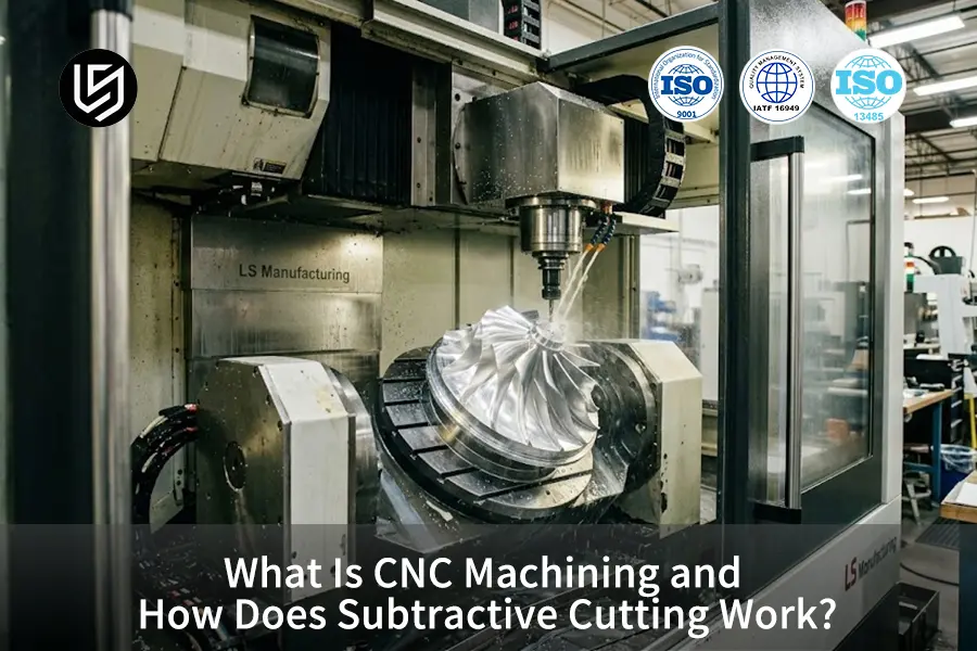
Precision Machining Baselines Key Points
- Material Shear Process: The fundamental process of CNC machining is the mechanical shearing of materials that causes the material crystals to slide across the shear planes instead of melting and wearing.
- Tolerances Category: Tolerances of the workpiece inherently fall into two categories which are standard machining (±0.025mm to ±0.05mm) and tooling grade precision (±0.005mm to ±0.01mm).
- Heat Dissipation Method: Chip formation becomes the primary method to dissipate heat; aluminum alloys dissipate over 80% of the heat from cutting operations using thermal conductivities of 130 to 167 W/(m·K) to evacuate cutting heat via chip formation.
- Geometric Constraints: Rotational cutter geometry dictates minimum internal corner radius (R ≥ 0.5 times the cutter diameter), avoiding sharp internal 90-degree corners.
About the Author of This Guide
This technical guide has been written by Gloria, Rapid Prototyping & Rapid Manufacturing Expert with Over 15 Years' Precision Engineering Experience at LS Manufacturing. For DFM case studies and tutorial videos, you can easily meet Gloria, Our manufacturing educator on LinkedIn.
What Is CNC Machining and How Does the Computer Interface Work?
CNC Machining (Computer Numerical Control Machining) refers to a subtractive automation technology for manufacturing physical parts from digital designs by way of tool path programming via computer control. The key mechanism in CNC machining involves the machine controller translating alphanumeric G-code inputs to movements of the servo motors, rotating cutting tools along multi-axis sliders to remove extra raw stock. General milling tolerance standards are ±0.025mm to ±0.05mm under ISO 2768-m, while calibrated machines provide tolerances of ±0.005mm to ±0.01mm on critical mating diameters. Nevertheless, there is always a physical limit involving the tool reach, spindle stiffness, and inability to remove square internal blind corners without radius clearance.
- Process Type: Subtractive computer-controlled material removal through mechanical shear
- Standard Tolerance Range: ±0.025mm to ±0.05mm (general ISO 2768-m) down to ±0.005mm (precise ISO 2768-f)
- Primary Process: Servo interpolation of G-code toolpaths
For the selection of appropriate machine configuration, here is a table comparing four major types of CNC machines by mechanisms, precisions, and geometry suitability:
|
Process Variant |
Kinematic Mechanism |
Typical Tolerance & Finish |
Optimal Geometric Applications |
|
3-Axis CNC Milling |
Workpiece fixed to table; rotating tool translates along orthogonal X, Y, and Z linear axes. |
±0.025mm tolerance; |
Planar mounting faces, shallow cavities, stepped brackets, and standard thru-hole patterns. |
|
5-Axis Simultaneous Milling |
Tool translates across X/Y/Z while two rotational axes (A/B/C) tilt and swivel simultaneously. |
±0.008mm tolerance; |
Complex aerospace impellers, organic prosthetic surfaces, and deep undercut draft geometries. |
|
CNC Lathe & Turning |
Cylindrical workpiece rotates at high RPM while single-point tool traverses axial/radial paths. |
±0.010mm tolerance; |
Axisymmetric shafts, precision bearing bushings, concentric hubs, and external/internal threads. |
|
Mill-Turn Multi-Tasking |
Rotary spindle indexing combined with live motorized cutting tools in a unified work envelope. |
±0.005mm tolerance; |
High-concentricity hydraulic spools, turned-milled aerospace fittings, and complete one-setup assemblies. |
In practical prototyping, axisymmetric turned features should remain on CNC lathes to minimize cycle times, whereas complex structural housings require simultaneous multi-axis kinematics to eliminate cumulative stack-up errors from manual refixturing.
How Subtractive Manufacturing Principles Govern Material Removal?
Subtractive manufacturing processes function via controlled physical shear deformation through the use of hardened flutes that subject metal stock to shear strength beyond its limits along narrow deformation planes. With the cutting edge penetrating the workpiece at calibrated surface speeds (like Vc = 350 to 500 m/min for 6061-T6 aluminum), the mechanical energy exerted converts into localized heat energy in the primary shear plane. Progressive shearing of excess stock results in continuous or fragmented chips to attain smooth finishes of Ra 0.8μm in finishing passes. Nevertheless, in materials with poor thermal conductivity or high elasticity, tool vibrations and springback effects create strict limitations on tolerances that can be attained.
- Shear Action: Micro-plastic shear deformation beyond crystal slip-plane limits
- Surface Finish Range: Ra 0.8μm (finishing milling passes) to Ra 3.2μm (roughing milling passes)
- Heat Transfer: Fast chip removal carrying heat energy from internal friction
To clear any misconception found on shop floors concerning machining processes, machining mechanics can be simplified into a four-stage micro-structural cycle per revolution of the cutter:
- Step 1: Elastic Compression and Primary Shear Zone Slip: The hardened carbide edge of the cutting tool cuts through the work material causing elastic compression. After the mechanical cutting load overcomes the alloy’s yield point, the atoms start to slip through the crystallographic grain boundaries in the primary shear zone to separate chips.
- Step 2: Chip Flow and Secondary Shear Zone Friction: The detached chip material moves along the rake face of the cutting tool at very high localized stress level. The friction is so intense that thermal spikes up to 600°C to 800°C occur at the tool-chip interface needing special tool coatings like AlTiN or TiCN to avoid crater wear.
- Step 3: Thermal Dissipation and Chip Ejection Mechanism: For alloys having good thermal properties like 6061-T6 aluminium with 130 to 167 W/(m·K) thermal conductivity, over 80 percent of the heat generated in cutting process escapes from the tool-chip interface by escaping through the exiting curly chips. On the other hand, poor chip ejection results in excessive heat build-up to alter part dimensions beyond ±0.01mm tolerance.
- Step 4: Tool Flank Rubbing and Springback: With the polished surface passing through the tool flank clearance, tiny amounts of springback happen at this interface. Spindle speed balance and small finishing depths of cut of 0.10 mm to 0.15 mm shear this boundary layer, yielding a consistent surface finish of Ra 0.8 μm.
Takeaway for Engineers: Accurate machining involves maintaining the dynamics of chip removal. When the rate of tool feed drops too much, the tool flutes polish and rub instead of cutting, causing localized hardening and thermal tool failure.
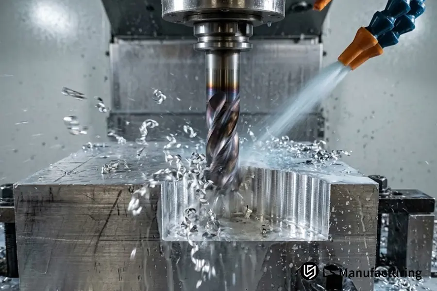
Figure 1: Multi-flute carbide end mill executing high-speed subtractive cutting on a 6061-T6 aluminum block with high-pressure coolant evacuating curly chips.
What Are the Primary Types of CNC Cutting Operations?
Kinematic principles employed in CNC cutting processes can be categorized as face milling, peripheral profiling of the side, and axial drilling. These operations involve performing roughing cuts along the z-axis in large depths (2.0mm to 5.0mm) prior to performing finishing step-overs (0.10mm to 0.20mm) in order to achieve surface finishes of Ra 0.8μm. The operations are defined by rigid spindle fixturing and cutter engagement angles. However, the operations have physical constraints that hinder their operation where deep internal pockets are involved due to long lengths compared to diameters of the tool.
- Core Operations: Face Milling, Peripheral Profiling, Precision Drilling & Boring
- Depth of Cut Strategy: Roughing depth (2.0mm to 5.0mm) vs. Finishing step-over (0.10mm to 0.20mm)
- Baseline Surface Output: Ra 0.8μm finish milling under rigid spindle fixturing
Kinematics of Face Milling as Compared to Peripheral Side Profiling
Face milling involves inserts that are installed around the flat face of large diameter tools. The major cutting is done orthogonally to the axis of the spindle, producing wide flat datum planes with regulated Ra 1.6μm finish quality. Peripheral side profiling involves removal of material by means of helical flutes around the perimeter of the tool. The accuracy of side profiling determines vertical wall straightness and cavities perimeters, although excessive radial depth of cut produces substantial lateral deflections leading to dimensioning taper of vertical walls.
Precision Holemaking: Peck Drilling vs. Single-Point Boring
The hole cutting process needs specific rotational techniques depending on the required tolerances. Regular peck drilling employs high-pressure coolant through the spindle to cut and eject the chips during the drilling of deep holes and ensures positional accuracy within ±0.05mm. In situations where there is a need for precise tolerances of ±0.005mm to ±0.01mm, the machinist will shift from the use of twist drill to adjustable single point boring bars. The boring cuts in one tangent line and therefore eliminates any wandering of the tool and hole roundness due to the initial drift of the drill.
Rule of Thumb: In the case of structural parts, flat datum must be set first using face milling prior to profiling.
Which Materials Are Most Suitable for High-Speed CNC Cutting?
Materials used in engineering vary significantly in their suitability for CNC machining due to the difference in shear strength, thermal conductivity and hardness envelopes. Alloys with a thermal conductivity of more than 100 W/(m·K) can endure fast surface cutting speed Vc = 350 to 500 m/min and tight dimensional tolerances of ±0.01mm. On the other hand, refractory metals and titanium alloys, which have very poor thermal conductivity, 6.7 to 7.5 W/(m·K), require low cutting speed, Vc = 40 to 60 m/min, in order to avoid deterioration of cutting edges due to overheating. Too elastic or hard material, HRC 45, results in severe tool vibration, friction and cutter breakage.
- Suitable Workpieces: 6061-T6 Aluminum, Brass C360, Delrin (POM), Pre-hardened 4140 Steel
- Thermal Conductivity Criterion: Materials with values >100 W/(m·K) allow for fast cutting
- Hardness Limitation: Best machinability HRC 32 to HRC 36 for structural pre-hardened steels
The engineering table below presents four different manufacturing materials and describes their cutting properties, appropriate linear speeds and thermal characteristics:
|
Engineering Material |
Thermal Conductivity |
Recommended Speed (Vc) |
Machinability & Thermal Behavior |
|
6061-T6 Aluminum |
130 to 167 W/(m·K) |
350 to 500 m/min |
Outstanding machinability; high heat evacuation through chips allows fast cycle times and ±0.008mm precision. |
|
316L Stainless Steel |
15.0 to 16.3 W/(m·K) |
80 to 140 m/min |
Work-hardens rapidly under rubbing; mandates positive rake angles and continuous feed to stay below hardened layer. |
|
Ti-6Al-4V Titanium |
6.7 to 7.5 W/(m·K) |
40 to 60 m/min |
Extremely low thermal conductivity traps ≥80% of heat in the tool edge; requires high-pressure coolant flood. |
|
4140 Alloy Steel (Pre-hard) |
42.0 to 45.0 W/(m·K) |
120 to 180 m/min |
Pre-hardened state (HRC 32 to 36) provides excellent chip breakage and surface stability holding Ra 0.8μm. |
When prototyping new functional components, specifying free-machining aluminum (6061-T6) significantly reduces tool wear and cycle time. If structural corrosion resistance mandates 316L stainless steel, tooling feeds must remain constant to avoid work-hardening the shear boundary.
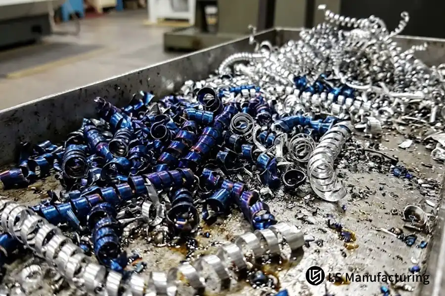
Figure 2: Macro view of chip formation illustrating thermal heat evacuation differences between heat-tinted blue titanium chips and ductile curly aluminum swarf.
What Are Crucial CNC Machining Limitations for Beginners to Know?
The CNC machining restrictions are caused by rotating cutter geometry, mechanical tool deflection, and stress relief in the raw stock. Due to the cylindrical shape of milling cutters that rotate around their own axis, it is impossible to cut square vertical internal angles without making a fillet radius that will be equal to or larger than the radius of the cutter. Moreover, in case the depth of cavity is higher than four diameters of the cutter (L/D > 4:1), the tool deflection leads to taper, chatter marks, and substantial lack of precision (more than ±0.05 mm). Additionally, in thin wall sections (<1.0 mm), the stresses will warp the workpieces beyond the acceptable tolerances.
- Geometric Boundary: Minimum internal corner radii (R >= 0.5 * cutter diameter; no R0 sharp corners possible)
- Deflection Limit for Tool: L/D ratio must not exceed 3:1 to avoid taper and chatter
- Cause of Distortion: Stress-induced warping in unsupported thin walls with less than 1.0mm thickness
Misconceptions by Beginners vs. Engineering Truths on the Factory Floor:
- Myth 1: Tolerances of ±0.005mm on all drawing dimensions ensure high-quality components.
- Engineering Reality:Arbitrary precision specifications create unnecessarily long manufacturing times. Commercial tolerances of ±0.025mm to ±0.05mm will serve 90%+ of structural fitments without adding unnecessary secondary grinding or inspection expenses.
- Myth 2: Sharp 90° pockets corners are allowed in CAD geometry.
- Engineering Reality: Rotating cutters will inevitably produce an internal corner radius. Creating sharp internal corners necessitates expensive secondary machining processes, such as wire EDM (Electrical Discharge Machining), or special broaching techniques.
To make sure that components stay affordable and easily manufacturable, it is recommended that junior engineers follow at least three Design for Manufacturing (DFM) guidelines:
- Design Rule 1: Allow Radius on Internal Pockets: Always make internal fillets slightly bigger than standard cutter radii (e.g., specify R3.2 mm instead of R3.0 mm when using a 6 mm end mill). It will allow the tool to move around the corners without stalling and will prevent chattering.
- Design Rule 2: Restrict Depths of Pockets: Never exceed three times the cutter diameter as depth of pockets (depth <= 3 * cutter width). Deep pockets will need special deep-cutting tooling, and cutting speeds should be reduced by 50 percent due to chatter risk.
- Design Rule 3: Minimum Wall Thickness is Essential: Ensure that metallic vertical walls have a minimum wall thickness of 1.0mm to 1.5mm (minimum of 1.5mm to 2.0mm for plastics). Thin unsupported vertical ribs tend to flex under cutter pressure and will produce a taper and chatter.
Following these design rules guarantees that your prototype part will easily convert into reliable volume production without any unexpected redesign of your tooling.
How Subtractive Cutting Works: Automotive Prototype Case Study by LS Manufacturing
For a recent automotive steering knuckle prototype development effort, design engineers needed a sturdy structural bracket milled from 6061-T6 aluminum to verify suspension kinematics under dynamic cyclic loading. The raw aluminum billet dimensions were 180mm * 120mm * 65mm, with two internal bearing bores that need to be fitted to ±0.01mm accuracy, whereas the rest of the lugs had the standard structural tolerances of ±0.05mm as per ISO 2768-m. The challenge for the designers was to manage thermal expansion in aggressive roughing hogging cycles without distorting bore roundness and coaxiality alignment.
The engineers at LS Manufacturing addressed the issue by dividing the cutting process into two thermally insulated operations.
Roughing was carried out with Vc = 420 m/min and deeper cuts up to 3.0mm using thermal conductivity of the aluminum alloy (130 – 167 W/m.K), and the removal of more than 80% of cutting heat through the departure of the curls of chips. After the rest cycle in the ambient conditions where the entire effect of thermal expansion was completely cooled off, the finishing process was carried out with the small radial step-over of 0.15mm at Vc = 480 m/min. Small tool engagement prevented deflection and the secondary shear chatter on the bore boundary.
Thus, the mechanical process ensured the stability of the dimensional tolerance at ±0.008mm, and the surface quality reached the value Ra 0.8μm. The yield rate for the component prototypes was reduced from 16.8% to 4.2%, and the machining cycle efficiency was improved by 12.5%. It is shown in this case study that the precision tolerances are achieved not because of the high spindle speeds but the balanced shear forces, heat dissipation, and fixturing stiffness.
Data Source & Verification: LS Manufacturing Shop-Floor Technical Log #AUTO-2026-104 (Empirically verified against LS Manufacturing 2025-2026 workshop machining database, total sample size >800 batches).
FAQs
What Is the Main Difference Between CNC Milling and CNC Turning?
The main difference lies in the kinematics of tool-workpiece engagement. During the CNC turning operation, the cylindrical workpiece rotates at a high RPM, whereas single-point tools make a linear motion for performing axial symmetric cut. During the CNC milling operation, multi-point cutting tools rotate at a very high RPM while the workpiece remains stationary and makes motions along the coordinate axes. At the LS Manufacturing Company, the processes often combine to create multi-functional machining centers for minimizing fixture-related errors.
Why does CNC Cutting produce such heat?
Heat is generated because of the process of plastic deformation in the primary zone of shear and sliding dry friction in the secondary zone of shear between the chip and rake face of the tool. In case the heat resistance is low during the cutting of alloy metals, it is necessary to control the temperature of the tool edge carefully. LS Manufacturing engineers develop the system of heat dissipation to make sure that almost all heat is dissipated in chips.
Can CNC machining produce precisely 90 degree internal vertical corners?
No, it cannot. Due to the fact that rotating cutters have a definite cylindrical radius, any internal vertical corners will have at least the same radius as the cutter. Whenever there is a necessity for square internal corners, LS Manufacturing will use additional sinker EDM to eliminate the remaining fillets, while designing extra large radii will be more cost-efficient.
Is it always advantageous to ask for better tolerances like ±0.005mm?
No. Tolerance grades ranging from ±0.025mm to ±0.05mm commercial tolerance grades guarantee superb fit, form, and function in more than 90% of all structural assemblies. Better tolerance grades of ±0.005mm to ±0.01mm require slower feed speeds, multiple spring passes, controlled temperature systems, and validation using a CMM, which makes everything expensive but doesn't improve the functionality of non-mating surfaces.
Conclusion
Knowledge of the physics of subtractive cutting in CNC machining makes possible the translation of clean CAD geometry into practical and mission-critical mechanical assemblies. Tolerance standards of ±0.01mm do not just consist of computer tolerances but are obtained through a balance of spindle torque, chip formation, heat generation, and clamping of the workpiece. Based on the realities of manufacturing, LS Manufacturing makes sure that we have strict kinematic validation procedures for all prototypes and production runs.
For researchers in universities, prototyping engineers and buyers who would like to examine the manufacturability of GD&T specifications, ensuring manufacturing feasibility helps avoid structural deformation and tooling delays. In case you are exploring the limitations of cutting speeds, thin wall deformations or material shear strength in multi-axis environments, our manufacturing engineering team will be glad to participate in academic debates and drawings peer review regarding feasibility. You can reach out to us through phone (+86 185 6675 9667), engage in kinematics equations with our technical team via email (info@lsrpf.com) or visit our dimensional checking capabilities at https://lsrpf.com/.
Further Reading: CNC Machining VS 3D Printing For EV Battery Enclosures: How To Choose?