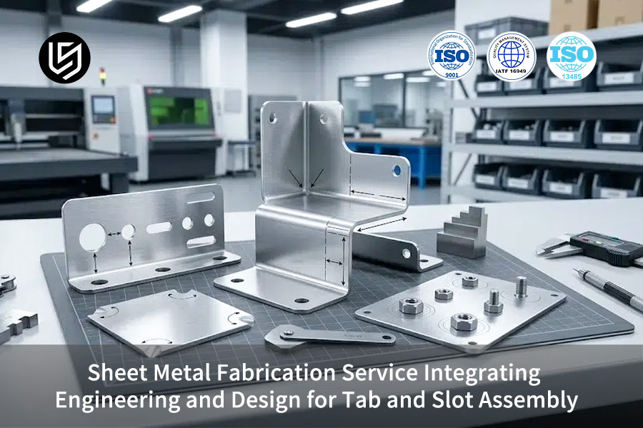
Sheet metal fabrication serviceis a highly accurate sheet metal personalization at a very advance level of industrial use that made use of. It mainly focuses on addressing the main problems of traditional chassis and enclosure manufacturing, i.e.high tooling costs, long sample lead times, and lack of control over assembly tolerances, through ain a combination of tab and slot self-positioning assembly process. In the medical, robotic, andnew energy vehicle sectors, traditional customized chassis rely on welding fixtures that are dedicated, the price for a single set of these can be over $3,500 USD, and the lead time for samples usually goes beyond 10 days.
LS Manufacturing has combined in its process thecontrol of tolerance at micron level, thermal stress compensation, and the depth of the coating that has been pre-determined, because of this enabling fixture-free, rapid mass assembly, and our clients are assisted in both reducing their initial investment and shortenin their project times.
Sheet Metal Fabrication Service Core Solution Overview
| Comparison Dimensions | Traditional Welding Assembly | LS Manufacturing Self-Fixing Process |
| Tooling Investment | Over $3500 (Jig Cost) | $0 |
| Sample Delivery Time | 10-15 days | 3-5 days |
| Assembly Assembly Tolerance | ±0.3mm or higher | ±0.1mm |
| Mass Production Yield | 85%-90% | Over 99% |
| Design Iteration Cost | High (Requires Fixture Remaking) | Low (Only Modify Digital Model) |
Key Takeaways:
- Eliminate Tooling Costs:Using self-fixturing design instead of hard fixtures completely removes tooling cost over $3500.
- Micron-Level Single-Sided Tolerance:Designing the slot X/Y axis withasymmetrical tolerances of +0.05mm to +0.12mmon each side perfectly offsets the cumulative errors of continuous assembly.
- One-stop efficient transformation:LS Manufacturing can cut the whole delivery cycle of chassis samples by 65% directly with its design and engineering integration.
Why Choose LS Manufacturing’s Slot and Tab Assembly Design for Sheet Metal Fabrication?
If you choose a sheet metal supplier with advanced engineering capabilities,you can avoid many assembly risks and lower costs throughout the project. LS Manufacturing's Slot and Tab assembly method is a result of several top-level project verifications and is a known way to assemble accurately without a fixture.
Thanks to our team of engineers who have specialized in high-end sheet metal Design for Manufacturing (DFM)for more than 10 years, and by strictly followingISO 9001:2015quality management system guidelines, our production processes are top-notch. This team can not only optimize digital models at the very start of a plan but can alsosimultaneously incorporate tolerance control, stress relief, coating compensation, etc. into design, because of this saving customers from reworking on a large scale during mass production.
Drawing on our extensive experience in new energy vehicle electronic control box projects, customers adopting this solution have been able tocut their initial tooling investment costs by 70%, while sample iteration speed hasimproved more than two times. When it comes to medical equipment, our product designs are fully compliant with theIEC 60601-1safety standard for medical electrical equipment and at the same time, they satisfy the most stringent protection requirements.
Mature engineering design can help you avoid 90% of the pitfalls in sheet metal assembly.Contact our senior sheet metal engineering experts fora free DFM (Design for Metal Fabrication) analysisto proactively identify project risks and cost optimization opportunities.

Why Single Side Tolerance Design Dictates the Quality of Sheet Metal Fabrication Service?
Traditional symmetrical tolerances are susceptible to the problem of tolerance accumulation. Designing single-side asymmetrical tolerance based on the maximum material boundary is themost effective way to ensure zero-gap locking when continuously assembling hundreds of parts. This is one of the major factors that influence the quality of sheet metal fabrication service.
How Cumulative Tolerances Lead to Mass Production Risks
Minor deviations are introduced during laser cutting and bending of multi-layer sheet metal, which arethe main variables used for determining the assembly yieldof sheet metal fabrication service, and eventually the level of delivery ofprecision sheet metal fabrication. These slight inaccuracies get added from one layer to the next, resulting in tolerance accumulation. If the fit clearance is exceeded,it will cause misalignment of parts and inability to fasten them.
Symmetrical tolerances, which go equally into positive and negative directions, will double the deviation range when added together, because of this increasing the risks of assembly.
LS Manufacturing's One-Sided Tolerance Control Standard
We use a single-sided asymmetrical tolerance design, which keeps the precise fit allowances for the tab and slot assembly only.All deviations are put on the slot side, and negative tolerances on the tongue side are very tightly controlled. This strategy reduces the cumulative deviation range right at the source and establishes a very accurate basis forindustrial sheet metal fabrication.
The core parameter benchmarks for standard sheet metal of different thicknesses are:
- 1.5mm Aluminum Plate:Tongue width tolerance -0.02mm, Slot width tolerance +0.05mm
- 2.0mm Stainless Steel:Tongue width tolerance -0.03mm, Slot width tolerance +0.07mm
- 3.0mm Carbon Steel:Tongue width tolerance -0.05mm, Slot width tolerance +0.10mm
Tab and Slot Fit Tolerance Parameters for Different Sheet Metals
| Sheet Material | Sheet Thickness (mm) | Tongue Width Tolerance (mm) | Slot Width Tolerance (mm) |
| 5052 Aluminum Plate | 1.5 | -0.02 | +0.05 |
| 304 Stainless Steel | 2.0 | -0.03 | +0.07 |
| SPCC Carbon Steel | 2.5 | -0.04 | +0.08 |
| 316 Stainless Steel | 3.0 | -0.05 | +0.10 |
According to internal test data, after adopting this tolerance standard, the first-pass yield of assemblies of 100 consecutive parts can reach 99.2%,far exceeding the industry average.
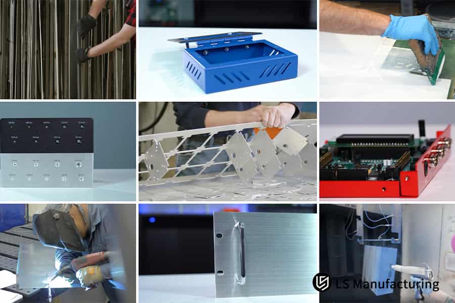
Figure 1: Grid of custom sheet metal enclosures, electronic chassis, and industrial fabrications.
How Do Engineering Teams Control Thermal Deformations During Weld-Free Sheet Metal Assembly?
The so-called fixture-free self-positioning assembly does not mean that no welding is done at all, it only means thatmortise and tenon structures are used as mechanical positioning fixtures. There have to be stress relief structures around the slots to counteract the minute tensile stress in the molten pool as it cools. This is probably the most neglected technical point in the process ofweld-free sheet metal assembly.
How Spot Welding Thermal Stress is Created
Spot welding at the slot positions willlocally heat the metal to a temperature point that it melts. This happens in weld-free sheet metal assembly and it is the main reason that the structural integrity of a medical grade sheet metal fabrication can be compromised. Along the cooling, the molten pool area's lateral shrinkage stress will be formed. If there is no stress relief design, then the shrinkage force will act the surrounding sheet metal andthis will result in warping and distorting the entire part.
Stress-relief Structure Engineering Design Proposal
LS Manufacturing installed stress-relief structures in metal fabrication patterns (DFM) step from the outset, making certain thatassembly accuracy and structural strength of tab and slot assembly are tackled initially. This is a prototype for strengtheningautomotive sheet metal fabricationdeformation resistance.
Major measures are:
- Stress-relief holes at slot endpoints:Circular vent holes witha diameter of 1.2mm to 1.5mmare added at both ends of each slot to disperse stress concentration points.
- Asymmetric interference fit design:Fine-tuning the local dimensions of the latches creates a slight interference fit, offsetting shrinkage after cooling.
Thanks to these two designs, the flatness of the spot-welded parts can becontrolled within 0.2mm/m, meeting the assembly requirements of high-end equipment.
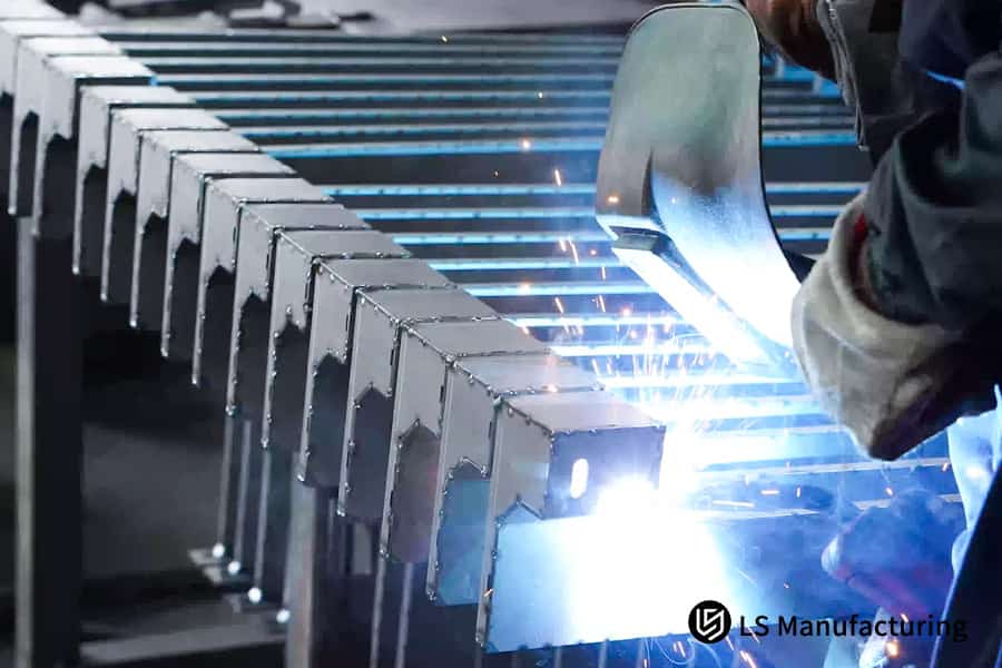
Figure 2: Workers performing precision welding on galvanized steel frames in a factory.
What Rules Guide the Coating Thickness Allowance in DFM for Sheet Metal Fabrication?
Ignoring surface treatment layer thickness in flat pattern design is a sure way to experience failures during assembly. Before sheet metal laser cutting,it is necessary to reserve micron-level space compensations for slotsbased on the powder coating or anodized layer thickness measurements. This is a key step in DFM for sheet metal fabrication that reflects engineering details.
Effect of Surface Finish on Mating Dimensions
The surface finishing of sheet metal parts creates a protective layer on the surface. Even though it is a detail often under-considered in DFM for sheet metal fabrication),it is a deadly point that should be handled very carefullyinprotective sheet metal fabricationsince it goes to actually increase the thickness of the material. If you do not save this margin when working on slot design, the latches after painting will not be able to go into the slots. And, if you forcibly insert them, the coating gets scratched,leading to a loss in corrosion resistance and an unsightly appearance.
Backward Compensation Operation at the Tiling Drawing Step
LS Manufacturing has compiledan extensive database of surface treatment layer thicknesses. Specific compensation rules have been formulated for different protection levels required by custom sheet metal enclosure service and forcoated sheet metal fabrication. Engineer while doing the tiling drawing, they implement the slot width correction in reverse directly.
The key compensation criteria are:
- Normal powder coating:0.08mm to 0.10mm one side coating thickness stocking.
- Outdoor high-protection powder coating:0.12mm to 0.15mm one side coating thickness stocking.
- Hard anodizing:0.03mm to 0.05mm one side oxide layer thickness stocking.
This pre-coating compensationeliminates the needs for manual grinding at the assemblystage, thereby helping maintain the surface treatment layer.
Why Is Laser Kerf Calibration Crucial for High Precision Sheet Metal Prototyping Service?
Laser kerf is a main factor that stands in the way of samples meeting assembly accuracy of ±0.1mm. High-tech laser control is indispensablein both the software compensation and physical correction of the molten slag flow path. Besides that, it is one of the main measures of the accuracy capability of asheet metal prototyping service.
The Effect of Laser Kerf on Assembly Accuracy
Metal laser cutting involves the beam melting and removal of metal, which results in a kerf with a specific width on the sheet metal.This is something important that determines dimensional accuracy in sheet metal prototyping serviceand a fundamental control point for high precision sheet metal fabrication. Without compensation, the actual cut dimensions will bedifferent from the design dimensions. The kerf width in most cases is in the range 0.15mm-0.22mm and changes as nozzle is being used.
Real-time dynamic compensation technology implementation
LS Manufacturing has rolled out a real-time dynamic kerf compensation system, which not onlystabilizes the dimensional reference for tab and slot sheet metal fabricationbut also makes easier micron-level precision control oflaser cut sheet metal, continuously modify the cutting path offset automatically after taking into consideration the sheet material, thickness, and nozzle condition.
Its main value is in two ways:
- Increased contact surface ratio:Guaranteeing that the actual contact surface between the latch and slot is more than 90%, so improving the mechanical integrity.
- Higher trial assembly first-pass rate:Doing sample assemblywith 99.4% first-through rate, This way leading to less sample iterations.
Laser Cutting Parameters and Kerf Compensation for Different Sheets
| Sheet Material | Sheet Thickness (mm) | Nominal Kerf Width (mm) | Dynamic Compensation Amount (mm) |
| SPCC Carbon Steel | 1.5 | 0.15 | 0.075 |
| 5052 Aluminum Plate | 2.0 | 0.18 | 0.09 |
| 304 Stainless Steel | 2.5 | 0.20 | 0.10 |
| 316 Stainless Steel | 3.0 | 0.22 | 0.11 |
Precise laser kerf compensation is the core guarantee for successful sample production on the first attempt. Simplysubmit your sample drawings, andwe will provide you with a free calculationof the sheet metal prototyping service's prototyping cost and precise delivery timeline.
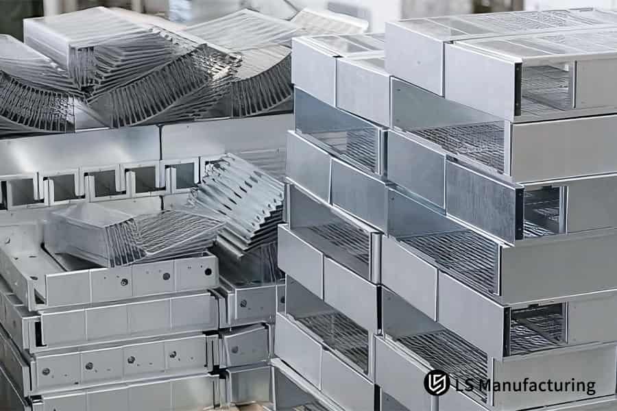
Figure 3: Stacked industrial stainless steel enclosures and fabricated metal components.
How to Optimize Tab Depth to Minimize Stress Concentration in self-fixturing sheet metal design?
One of the primary causes of dynamic stress concentration in the tab is the sharp corner at the base of the tab. Fatigue fracture under a severe vibration environment can only be avoided bychanging the tab depth to 0.6-0.8 times the plate thickness and by adding a specially designed radius (R-angle).This is a key design rule for hanging up the structural life inself-fixturing sheet metal design.
Stress Concentration Failure Modes of Tab Root
During a high-frequency vibration and very dynamic load condition, a stress concentration point will occur at the right angle on the tab root. This is themain defect point that affects the structural lifespan of the self-fixturing sheet metal designand also the point that makes designing thevibration-resistant sheet metal challenging. Continuous exposure to alternating shear stress will cause the root to form micro cracks that, over time, will cause the tab to break. The design that uses a tab depth of 0.5 - 0.75 times the plate thickness based on industry standards doesnot take fatigue under vibrations into account at alland because of this, results in a high failure rate.
Parameter Standards for Optimized Design
With the help of vibration test data,LS Manufacturing has come up with the optimized latch design standards, which is now our benchmark for handling the high-dynamic load condition and on top of that, we have even come up with a detailed design specification forfatigue-proof sheet metal fabrication.
- The latch depth should be set to0.6 - 0.8 times the sheet thicknessas this will mitigate the shear stress at the root.
- The latch root should be designed to have a retraction angle of at least R0.5mm to transform the stress point concentration.
Our test that measures the three occasions when the most impact is given shows that a latch that has been optimized canresist the impact loads 35% more times than a normally right-angle latch.
Which Bend Deduction Calibration Model Guarantees Seamless Alignment in tab and slot sheet metal fabrication?
Multi-bend continuous slot parts have an extremely tight tolerance for bend deduction. It is necessary to rely on physical measurements andadjustments based on the bending die's V-width and the blanking texture. This is a fundamental condition for achieving accurate positioning after multiple bends in tab and slot sheet metal fabrication.
Reasons for the Failure of the Universal Bending Factor
In the industry, the universal universal K-Factor is the most common tool to determine bend deduction. But this universal factor isnot enough for high-precision fitting of tab and slot sheet metal fabricationand can not meet the precision assembly requirements ofmulti bend sheet metal fabrication. This factor is determined from an ideal sheet material. Though, in reality, the effect of therolling direction of the sheet material and die wear on the final bending dimensionscan not be ignored. After multiple bends, slot misalignment occurs due to the accumulation of deviations.
Steps of Actual Measure and Calibrate
By establishing an actual measurement and calibration bending deduction model, LS Manufacturing shifts the actual measurement verification operation to the DFM for sheet metal fabrication process.It gives a basis for a mechanism of actual measurement and calibrationforpress brake sheet metal fabrication. First-piece measurement is carried out for each batch of sheet metal and the current mold condition.
The main calibration activities can be summarized like this:
- Blanking Direction Detection:Measurements of bends for the transverse and longitudinal blanking are taken, and the bending deduction factors are corrected so for the different directions.
- Unscrew Groove Modification:To prevent material bulging and slot compression, the width of the unscrew groove at the bend is controlled to belarger than 1.5 timesthe thickness of the metal sheet.
By actual measurement and calibration, the slot coaxiality deviation after multi-stage bending can belimited to 0.05mm, which is the precise assembly requirement of continuous slots.
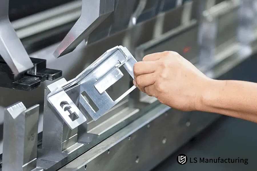
Figure 4: Worker testing precision fit of tab and slot sheet metal parts in a bending machine.
How to Maximize Material Utilization to Reduce Custom Sheet Metal Enclosure Service Costs?
The density and pattern of tabs have a major influence on the metal sheet nesting ratio.Properly spacing tabs often means a substantial decrease in the purchase of materials, while maintaining stiffness. This way, it becomes an important way to reduce the total cost ofcustom sheet metal enclosure servicethrough cost optimization.
The Impact of Tab Arrangement on Nesting Rate
Tabs lead outside the perimeter of the sheet metal body and because of this impose several dead zones that cannot be used for nesting. This is a major point of optimization if one wants to control costs in custom sheet metal enclosure service and themain direction for smart sheet metal fabrication to achieve cost-effective results. More minor tab spacing means more dead zones which are not used, and the raw material utilization is lesser which directly leads to increased product material costs.
Using Optimized Material Layout to Cut Costs
Besides providing the processing services, LS Manufacturing also keeps a supply chain perspective in mind, exploring ways tooptimize material utilization to jointly lower the overall sheet metal fabrication services procurement costand get the most of material benefits brought byhigh-yield sheet metal fabrication.
The two main core optimization methods are:
- Scientific Adjustment of Tongue Spacing:Raising the tongue spacing from the regular 50mm to the 120mm-150mm range will lessen the edge dead zones.
- Nested Common-Edge Cutting:By using the common-edge cutting technique, a double-edged cut can be made between two adjacent parts, which results in less waste.
Comparison of Material Utilization Rates for Different Tongue Spacings
| Tongue Spacing (mm) | Material Utilization Rate | Unit Material Cost (USD) | Relative Cost Reduction |
| 50 (Standard) | 62% | 8.5 | 0% |
| 100 | 71% | 7.3 | 14% |
| 120 | 76% | 6.8 | 20% |
| 150 | 73% | 6.4 | 25% |
Optimizing material layout can directly reduce procurement costs without affecting performance.Contact usfor a customized optimization solution tohelp you calculate the specific cost reduction potentialof your custom sheet metal enclosure service.
Case Study: How LS Manufacturing Engineered a Medical Robotic Control Enclosure Using Custom Sheet Metal Enclosure Service?
Client Challenge
A first-class surgical robot manufacturing company was in a pressing situation to personalize a batch of highly protective, multi-compartment medical robot control enclosures. Their demands formedical device sheet metal fabricationwere, in fact,extremely high for both precision and delivery. The product features a highly complicated structure internally with 8 sides of assembly plates and 12 slot mating positions.
With traditional ways of doing things, custom-made sets of dedicated welding fixtures would be necessary. The customer, as per their initial calculations, figured thata single set of assembly and welding fixtures would already be as costly as $3,800. Besides, the manufacture of fixtures would take another 14 days, thereby directly holding up the important milestone of the new product introduction.
LS Manufacturing Solution
- After that to our B2B sheet metal engineering team handling the project, they revamped the product's 3D digitalmodel fully, converting the traditional pure fixture assembly solution intoa high-precision tab and slot self-positioning and self-clamping design.
- Utilizing a self-developed three-level cumulative tolerance simulation model for simulation validation, the team achieved the precise setting of theone-sided tolerance of the slot to +0.06mm, so completing the solution from design to production ofsheet metal parts.
- Stress-relieving dumbbell holes of 1.2mm were introduced in all spot welding stress overlapping zones to counteract the welding thermal deformation effects.
- In parallel,a 0.10mm tolerance for medical-grade powder coating was kept constantduring the stage of material preparation of the tiling drawing.
- The team also enhanced the latch arrangement and resorted to a common-edge cutting method to save material.
Results and Value
On the strength of this self-positioning slot technology incorporating thorough design and engineering capabilities, each part was capable of self-aligningwith high accuracy assembly at ±0.1mmpractically doing away with the manufacturing of any dedicated hard tooling fixtures. This was a confirmation of the engineering viability of thefixtureless sheet metal fabrication.
The core data comparison of the process solutions for this medical robot control box project is as follows:
| Comparison Item | Traditional Welding Assembly Process | LS Manufacturing Self-Positioning Slot Solution |
| Dedicated Hard Tooling Fixture Cost | $3800 | $0 (Fully Waived) |
| Sample Delivery Cycle | 15 days | 4 days |
| Assembly Self-Alignment Accuracy | Relies on manual adjustment, large deviation fluctuations. | ±0.1mm |
| Overall Delivery Efficiency | Industry benchmark level | 73% improvement |
| Medical-Grade Compliance Testing | Requires multiple rounds of repair and adjustment. | Passed rigidity fatigue and protection level tests on the first attempt. |
The customer stated in the acceptance report:"LS Manufacturing's DFM engineering and sheet metal detail works are second to none in the industry."
A mature engineering solution can simultaneously help you achieve cost reduction, speed increase, and efficiency improvement. Upload your 3D model, and we willprovide you with a customized quote and complete engineering optimization planfor custom sheet metal enclosure service within 24 hours.

FAQs
Q1: What is the average lead time for a custom sheet metal enclosure service quotation?
LS Manufacturing boasts an interactive DFM intelligent analysis system. Once youshare your 3D design filesin STEP format with us, we are capable ofgiving you a precise quote within 24 hours. This quote will include the production solutions and manufacturability assessments, as well as detailed technical optimization feedback and risk warnings.
Q2: How does a tab and slot sheet metal fabrication method minimize the total assembly expense?
Built-in mechanical positioning features or self-positioning latches replace parts and completely eliminate the necessity for costly welding fixture development. Besides, they help a lot in cutting down the time for manual repair really during assembly, so in the end, overall assembly costs and NRE (Non-Renewable Equipment) engineering costs are reduced, and project lead times are shortened.
Q3: Do your sheet metal prototyping services keep multi-part industrial assemblies to truly tight tolerances?
Correct. Our production capability includes high-power fiber lasers and very precise CNC bending machines, and with real-time dynamic kerf compensation technology, we can constantly keep theoverall cross-sectional tolerance of multi-layer interlocking assembly samples within the ±0.1mm range, which pretty much complies with the very high demands of precision assembly.
Q4: What are the materials processed through your top-quality sheet fabricating services?
We offer precision machining services fora full range of sheet metal with thicknesses from 0.5mm to 6.0mm, covering 5052 and 6061 series aluminum sheets, 304 and 316 stainless steel, and SPCC cold-rolled carbon steel, as well as various mainstream industrial materials, and support diverse customization needs.
Q5: How do you keep the sheet metal parts from being scratched during your weld-free assembly steps?
The highest quality laser protective film is constantly applied to the sheet metal during the cutting stage and the bending process molds use a scratch-free polyurethane design. These measures guarantee that the parts remain scratch-free from the first to the last process andthe finished product is ready for subsequent surface treatment processessuch as anodizing and powder coating.
Q6: Can tab and slot assembly be used for low-volumeproduction or is it only feasible for mass manufacturing runs?
Tab and slot assembly technique can be usedfor small-batch prototyping as well as mass production. In fact, the removal of the fixture development cycle and cost can figure small-batch prototyping iterations at the same time that batch repeatability and consistency are ensured in mass production.
Q7: What is your method for powder coating thickness compensation in DFM for sheet metal fabrication?
Our team first estimates the powder coating thickness (ranging from 80μm to 120μm) and thenmakes a reverse space compensation while the laser cutting pattern is being generated. In this way, the slots will fit each other smoothly after coating, which means no coating scratches and jamming will occur.
Q8: Can you give me some reasons for selecting LS Manufacturing as my engineering-oriented tab and slot sheet metal supplier in China?
LS Manufacturing has a team of engineers with DFM skills at the factory, designs with zero-fixture-cost advantages, and a stringent ISO quality traceability system. Together, these reduce your B2B global supply chain risks quite a bit, therebygiving you stable and dependable long-term delivery and technical support.
Summary
R&D speed and upfront investment in hardware development are the two factors that mainly determine a product's competitive advantage in the market today. With deep engineering and design, the tab and slot self-positioning assembly process can help companiesnot only eliminate expensive rigid assembly fixtures, but also the loss of final product qualitydue to cumulative sheet metal tolerances and thermal stress deformation can be fundamentally prevented.
LS Manufacturing leads the technical way in the core control of product quality and cost reduction. Single-sided tolerance definition, scientifically reserved surface layer thickness, and precise laser cutting compensation form an intricate control system thatturns process advantages into direct cost and time advantages. All these, together with a deeper benchmark solution for global B2B precision sheet metal processing, are contributed by this company.
Are you willing to take advantage of Advanced DFM Engineering and get rid of Fixture Costs that are Expensive?Your product launch cannot be delayed by inefficient traditional assembly. Reach out to our senior sheet metal engineering experts now and get world-class DFM engineering support at the earliest stage of your project. Onlyupload your 3D CAD modelto our safety assessment system in 2 minutes, and our expert team will do a complete manufacturability analysis and give you a highly competitive tiered mass production quote within 24 hours, that is, your worry-free manufacturing journey has started!
📞Tel: +86 185 6675 9667
📧Email: info@lsrpf.com
🌐Website:https://lsrpf.com/
Disclaimer
The contents of this page are for informational purposes only.LS Manufacturing servicesThere are no representations or warranties, express or implied, as to the accuracy, completeness or validity of the information. It should not be inferred that a third-party supplier or manufacturer will provide performance parameters, geometric tolerances, specific design characteristics, material quality and type or workmanship through the LS Manufacturing network. It's the buyer's responsibility.Require partsquotation Identify specific requirements for these sections.Please contact us for more information.
LS Manufacturing Team
LS Manufacturing is an industry-leading company. Focus on custom manufacturing solutions. We have over 20 years of experience with over 5,000 customers, and we focus on high precisionCNC machining,Sheet metal manufacturing, 3D printing,Injection molding.Metal stamping,and other one-stop manufacturing services.
Our factory is equipped with over 100 state-of-the-art 5-axis machining centers, ISO 9001:2015 certified. We provide fast, efficient and high-quality manufacturing solutions to customers in more than 150 countries around the world. Whether it is small volume production or large-scale customization, we can meet your needs with the fastest delivery within 24 hours. choose LS Manufacturing. This means selection efficiency, quality and professionalism.
To learn more, visit our website:www.lsrpf.com