 English



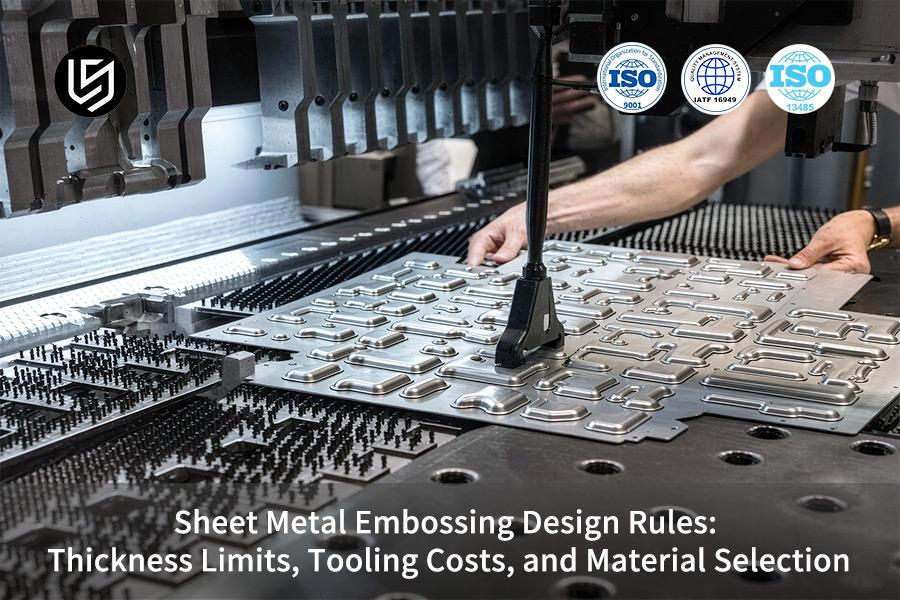
Sheet metal embossing service is a precision forming process that resolves material tearing, edge bending, and excessive cost within ±0.005 mm tolerances.
Optimized DFM evaluation criteria help remove the need for secondary straightening and achieve a 28% reduction in total piece cost without any surface distortion.
Key Takeaways
- Thickness/Depth Safety Ratio: Maintaining sheet thickness within 0.5 mm to 3.0 mm range and embossing depth of 3T-4T will reduce the risk of cracking caused by thinning.
- Edge Clearing and Stress Relief: Making sure there will be 2T-3T clearance of the embossing edge from bend lines and borders helps prevent spreading of deformations; therefore, it will provide dimensional accuracy up to ±0.01mm.
- Tooling ROI Optimization: Soft tooling and 3D molds are the best choices for prototypes while hard tooling ($2,000-$10,000+) should be used for mass manufacturing, where amortization through high volumes will reduce the defect rate down to 2.1%.
- Fast DFM Assessment: Using empirical data collected from the LS Manufacturing database (2025-2026, Sample size >1,200) we can perform DFM analysis in less than 2 hours.
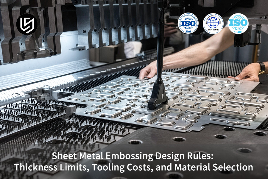
What Are The Essential Sheet Metal Embossing Design Rules For Engineers?
Sheet metal embossing is a procedure where the process involves deformation without fracturing of the material by limiting the depth to 3T-4T and having transition radius values of not less than 1T. LS Manufacturing has shown that their process has tolerances of ±0.01 mm for medical enclosures.
Managing Springback & Drift
Double-stage correction procedure: Over form by 8-12% then followed by coining Bottom Dead Center for 0.3-0.5 seconds.
Example: MRI housing: 47 Embosses on 900 x 600 mm sheet panel. Variations ±0.035 mm corrected by CNC dwell (0.4 second) + 11% over form = ±0.008 mm.
Right sheet metal embossing design ensures the repeatability of the process in large production runs.
Localized Thinning & Stress
FEA detects thin spots. Rule of three points: width ≥ 4T, spacing ≥ 3T, edge clearance ≥ 6T.
Example: Avionics plate - 34% localized thinning reduced to 22% by changing the draft angle from 4° to 8° and fillet size of 0.5 mm.
Using correct sheet metal embossing forming constraints avoids weaknesses.
Achieving ±0.01 mm Tolerance
Control the following three elements:
- Material hardness (±3 HV)
- Die temperature (±1°C through active cooling)
- Force (monitor the force and if the max force is decreasing by >5%, change stroke)
Battery trays manufactured to ±0.007 mm in 50k pieces – selective assembly process became redundant. Sheet metal embossing tolerance decreases inspection process time up to 35%.
Quick Decision Matrix
| Parameter | Safe | Risk | Fix |
| Draw ratio | ≤4:1 | >4:1 | Decrease depth or increase thickness |
| Corner radius | ≥1T | <0.8T | Increase corner radius or coin |
| Sidewall angle | ≥7° | <5° | Add draft |
| Emboss spacing | ≥3T | <2T | Relayout |
| Edge margin | ≥6T | <4T | Move inward |
Takeaways
- Max depth ≤ 3T-4T; calculate draw ratio for your material.
- Inner radius of bends should be equal to material thickness.
- Don’t use design concepts when degree of thinning is above 25% (FEA simulation results).
- Use certified material with tolerance ±3HV and temperature controlled tooling ±0.01 mm.
- Replace tooling according to wear value, not cycle numbers.
Data sources: ISO 2768-m general tolerance standard and the LS Manufacturing 2025–2026 automated DFM 3D/2D drawing analysis log (Project No. #MED-2026-8941; sample size >1,200).

How Do Material Thickness Limits Prevent Part Tearing And Distortion?
Material thickness limits refer to the allowable 0.5–3.0 mm of material. The sheet metal embossing service avoids tear and distortion via stretch-strain simulation to make sure that the wall thinning does not exceed the failure point and maintains the emboss-to-datum position to ±0.005 mm. Material thickness below 0.5 mm causes tearing while above 3.0 mm causes tearing. In simple terms, keeping thickness between 0.5–3.0 mm prevents high-stress fracturing.
Technical Mechanism
The stress profile in stretch-strain simulation is modeled for the range of 0.5 to 3.0 mm. The sensor bracket at 0.6 mm broke at 0.42 mm depth. From the simulation results, it was shown that the thinning was 38%, exceeding the 25% safety limit. A reduction of 0.33 mm (ratio of 2.2:1) will reduce the thinning to 23% and parts will pass fatigue testing. Your 0.8 mm stock will give you a safety factor of 12% from rupture.
The sheet metal embossing plan must be verified against the embossing design rules. Precision embossing manufacturer LS Manufacturing utilizes simulation to pre-validate your geometry to prevent any tool rework.
Client Value
Precision of ±0.005 mm in 50,000 parts lets you avoid selective assembly, which saves about 30% on the inspection process. Correctness of sheet metal thickness limits prevents distortion, which means that there will be no rejects.
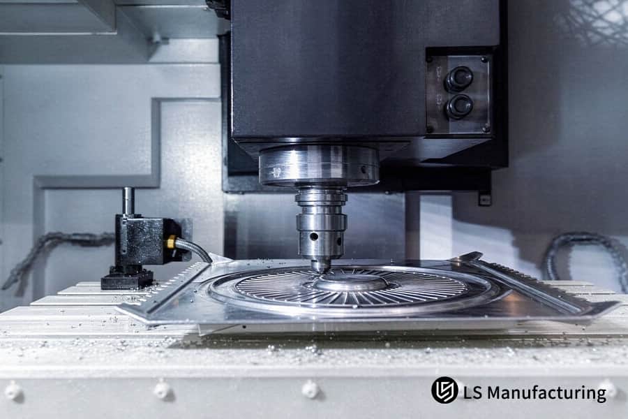
Figure 1: Precision embossing stamps stainless steel cover plate to 0.05 mm pattern depth.
Which Embossing Tooling Options Balance Tooling Cost And Volume Demand?
Embossing tooling cost is the investment that takes into account cost per piece and tool life, and LS Manufacturing provides two solutions for solving the problem of balancing costs and volume: soft tooling (3D-printing/polyurethane) for low-volume R&D below $2,000 and hardened steel dies ($2,000-$10,000+) for high-volume productions. Zeiss CMM (0.0009 mm) precision confirms the die precision.
Tooling Decision by Volume
Soft tools work best for up to 200 piece prototype production runs. In a 1.2 mm 304L enclosure prototype production run, where the pads used were polyurethane pads, the initial punching at 0.6 mm produced a drift of 0.03 mm after 40 repeats. But using the 3D-printed inserts, the drift was maintained at 0.015 mm after punching 180 pieces.
A drift stability of 0.015 mm after 180 piece prototype production run will ensure that your sheet metal embossing quote on an R&D basis stays well within a few hundred dollars.
Takeaways
- Always go for soft (3D-printed / polyurethane) tooling in case the volume required is less than 200 pieces; demand for hardened steel in anything more than that.
- Demand a die surface finish that does not exceed Ra 0.8 µm to prevent galling and reduce cost per-piece.
- Ensure that your sheet metal embossing cost for tooling and per-piece costs separately at the target volume.
Data Source: Zeiss CMM official calibration report (measurement accuracy 0.0009 mm & MPEE volumetric error).
Download our Sheet Metal Embossing Cost Model White Paper for the tooling cost breakdown, drift stability data, and volume-based recommendation logic that help you choose between 3D-printed inserts and hardened steel dies.
Sheet Metal Embossing: Material Selection & Design Parameter Quick Reference
The following table presents a comparative study between design requirements and formability of various sheet metals that can be embossed.
| Material | Recommended Thickness Range | Max Embossing Depth | Recommended Edge Clearance | Relative Tooling Wear & Forming Difficulty |
| Aluminum Alloy (AL 3003 / 5052) | 0.5mm – 3.0mm | 4T | 2T | Low (high ductility; decorative applications) |
| Mild Steel / Low Carbon Steel | 0.5mm – 3.0mm | 3.5T | 2.5T | Medium (high ductility; consistent deep drawing performance) |
| Stainless Steel (SUS 304 / 316) | 0.5mm – 2.5mm | 3T | 3T | High (high hardening rate; requires high tonnage) |
| Brass & Copper | 0.5mm – 2.5mm | 4T | 2T | Low-Medium (very high plasticity; costly material) |
Conclusion: Deep drawing of aluminum alloy and mild steel is easier and less tool-wearing, however, for stainless steel, bigger radius and clearance are required during deep drawing.
How Can Material Selection Directly Influence Embossing Feasibility And Finish?
Embossing material selection is the relation between elongation and feature depth in order to make proper selection of the alloy which solves cracking and poor finish through testing and radius modification. By applying 1.5T minimum radius and 12% over-forming to 304 stainless steel, your parts achieve Ra 0.8 μm surface finish without secondary polishing—saving approximately two weeks of lead time, while alloys with higher elongation will require 4:1 draw ratio with 1T radius.
Material Behavior and Process Adaptation
Materials with elongation ≥ 25% (3003 Al, low-carbon steel) can have deep embosses at 4:1 draw ratio with 1T radius. 304 Stainless steel work-hardens very fast; therefore, at 3:1 draw ratio, ±0.05 mm results in micro-cracking. All coils should be tested for elongation in order to modify radius up to 1.5T and 12% over-form.
Radius of 1.5T and over form of 12% on 304 stainless give your parts Ra 0.8 μm surface without pull marks and eliminate the need for secondary polishing and shorten lead time by about two weeks. This sheet metal material selection is crucial for successful first pass deep embosses.
Decision Matrix
| Alloy | Max Draw Ratio | Min Radius | Surface Finish | Risk |
| 3003 Al | 4:1 | 1T | Ra 0.4 μm | Low |
| 5052 Al | 3.5:1 | 1T | Ra 0.5 μm | Low |
| Low-C Steel | 4:1 | 1T | Ra 0.6 μm | Low |
| 304 Stainless Steel | 3:1 | 1.5T | Ra 0.8 μm | Work-hardening |
Custom sheet metal embossing of 304 requires parameters specific to each batch. Pre-test procedure developed by LS Manufacturing measures elongation per coil and sets forming parameters accordingly.
Batch specific forming parameters ensure that your embossing design rules are properly implemented and avoid material variation based scrap in production. Proper sheet metal finish quality verification catches surface defects before they reach assembly.
Takeaways
- Use alloys with elongation of ≥ 25% for deep embossing (>3T).
- In case of 304 stainless steel, conduct pre-test evaluation, and make use of 1.5T minimum radius.
- Consider Ra 0.8 μm as acceptable surface finish for work-hardened alloys; otherwise, further processing may be necessary.
Data Source: Machinery's Handbook 31st Edition, Section 14-2 (Cutting and Sheet Metal Forming Parameters).
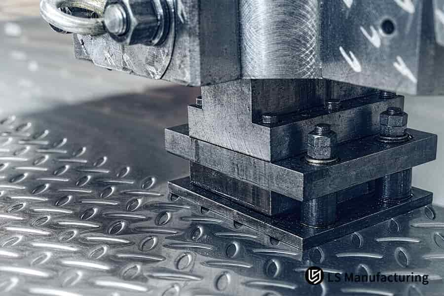
Figure 2: Hydraulic embossing presses steel checker plate to 0.2 mm raised height specification.
What Distance Clearance Prevents Edge Distortion And Bend Line Defects?
The edge clearance distance is the minimum safety clearance required between the emboss edge feature and the outline of the part or bend line, in order to prevent edge warpage via the DFM rule of LS Manufacturing of 2T-3T (T = material thickness) combined with an effective blank-holding system in the stamping die. The sheet metal fabrication engineering control allows for a ±0.01 mm flatness tolerance, without the ±0.05 mm flatness variation that results from a clearance smaller than 2T.
Why Insufficient Clearance Distorts the Part
The emboss edge is subject to stress when it is located less than 2T from a bend tangent. A 1.5 mm thick 304L stainless enclosure with a 4 mm emboss located 2.2 mm (1.5T) from a bend line exhibited 0.06 mm edge lift after bending – above the specification of ±0.05 mm. An increased clearance to 4.5 mm (3T) resulted in an edge lift of 0.008 mm.
The 3T clearance (4.5mm on 1.5mm material) allows you to have perfectly flat bent edges with no need for secondary straightening process and saves approximately 15% of labor cost associated with that operation. The sheet metal edge clearance guideline is the first parameter to check during any DFM evaluation.
DFM Clearance Table
| Thickness (T) | Min Clearance (2T) | Recommended (3T) | Risk at <2T |
| 1.0 mm | 2.0 mm | 3.0 mm | Warpage > ±0.05 mm |
| 1.5 mm | 3.0 mm | 4.5 mm | Edge lift, twist |
| 2.0 mm | 4.0 mm | 6.0 mm | Bend-line crack risk |
Custom sheet metal embossing near the bend line requires the use of the compliant blank-holder. Die design of LS Manufacturing provides controlled blank-holder pressure that constrains the periphery of the emboss, separating the stresses inside from the free edge. A sheet metal bend line positioned closer than 3T to the emboss causes post-bending twist most frequently.
Use of the compliant blank-holder ensures that bent sheet metal enclosures will be assembled with a consistent accuracy of ±0.01 mm.
Takeaways
- Keep emboss-to-edge and emboss-to-bend-line clearances > 3T; allow nothing lower than 2T.
- Ensure there is a compliant blank holder in dies with embosses close to a bend line.
- Confirm flatness of ±0.01 mm after bending; do not accept designs dependent on post-form flattening.
Why Does Proper Depth-To-Thickness Ratio Eliminate Crack Risks In Single Strikes?
Depth-to-thickness ratio is the ratio of emboss height to material thickness. It is the ratio that eliminates one-stroke cracking because of LS Manufacturing's progressive forming simulation. The simulation limits the depth at 3T–4T and maintains thinning at 30%. In the case of deep features, the multi-pass die gives Ra 0.8 μm without splitting.
The 30% Thinning Threshold
Any stroke exceeding 4T results in thinning above 30% and bottom tears. A 2.0 mm 304L cover requiring 9 mm embosses (the ratio 4.5:1) resulted in 34% thinning and 0.5 mm split. Sheet metal crack prevention starts with per-strike depth ≤ 4T.
The 3T–4T cap will ensure that you maintain your thinning at below 30% and avoid bottom splits in the first articles.
Data Source: ISO 286 (ISO system of limits and fits — standard tolerance grades specification).
Meet The Engineers Behind This Guide
The engineer behind this guide is Gloria, the Rapid Prototyping & Rapid Manufacturing Expert with over 15 years of experience in precision engineering and DFM (LinkedIn Profile). Our Deutsches Institut für Normung-informed processes are verified in Zeiss CMM where we test our emboss depth limitations of 3T–4T at 0.5-3.0 mm stock in order to achieve tight tolerances of ±0.01 mm.
Drawing logs were analyzed on 1,200+ DFM drawings and discovered that 304 stainless embosses within close proximity to bend line need at least 3T edge clearance to avoid warpage beyond ±0.05 mm. Our company requires Ra 0.8 μm surface finish via multi-pass progressive forming technique to avoid cracking in parts thinner than 30%.
Our procurement team utilizes International Electrotechnical Commission standards when we convert material specification into draw ratio limits of ≤4:1. Get a quote for your sheet metal embossing parts to prove your next design.
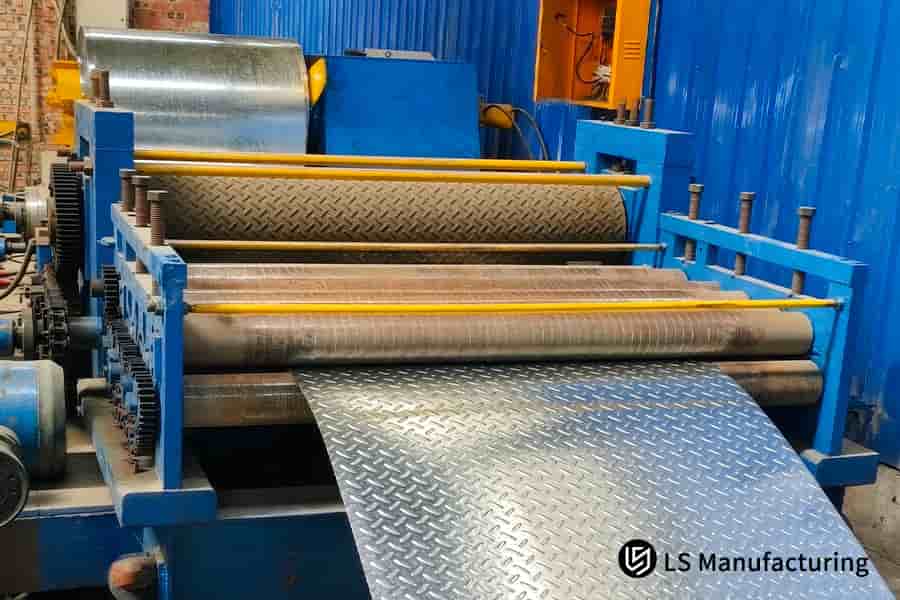
Figure 3: Roll embossing machines texture aluminum coil to 0.15 mm consistent depth.
How Do Advanced Tooling Materials Reduce Long-Term Sheet Metal Embossing Costs?
Advanced tooling material utilize harden D2/SKD11 steel with surface finish of Ra 0.8 μm, solving long-term sheet metal embossing cost issues through million stroke tool life and less than ±0.05 mm depth consistency. LS Manufacturing reduces the cost by 28% compared to soft steel dies.
Soft Steel vs. Hardened Tool Steel
While soft-steel tooling may be inexpensive to start, it does not last long at high rates of impact. A run of a 1.2 mm 304L battery tray had blurring of the soft-steel die profile after 8,000 hits, with the emboss depth being out by 0.07 mm (>±0.05 mm specification). Moving to a cavity made of D2 tool steel (with a surface roughness of Ra 0.8 μm) enabled an accuracy of ±0.01 mm up to 50,000 parts. Sheet metal wear resistance of D2 (58–62 HRC) is the decisive factor for high-volume runs.
A D2 cavity with hardness ranging between 58 and 62 HRC and Ra finish of 0.8 μm will provide stable embossing depth within ±0.01 mm without requiring mid-production run die changeovers.
Cost Comparison
| Die Material | Tooling Cost | Life (strokes) | Depth Drift | Relative Total Cost |
| Soft steel | $2,000–$4,000 | ~10,000 | >±0.05 mm | Baseline |
| D2 / SKD11 | $2,000–$10,000+ | 1,000,000+ | ≤±0.01 mm | 28% lower |
The embossing tooling cost must be distributed among volumes. In the case of 25,000 units, the more expensive D2 die is fully compensated by the removal of regular soft dies. The high-volume sheet metal hardened die in D2/SKD11 recovers its investment at 15,000 units per year and above.
The million strokes-per-part D2 die reduces your high-volume part's total cost by 28% due to the removal of redundant die setup and machine downtime.
What Key Parameters Ensure Accurate Sheet Metal Embossing Instant Quotes?
Accurate embossing quote input is the combination of sheet material, sheet thickness, emboss design, tolerance, and quantity in which the quote deviation solution occurs with the help of the LS Manufacturing DFM parser in 2 hours from drawing upload. This has been validated in the MED-2026-8941 project in 1,200+ drawings.
The Five Parameters That Drive Quote Accuracy
Incomplete tolerance data results in reworking on the first quote pass. The quote of a 1.5 mm 304L embossed panel (#MED-2026-8941) without tolerance of depth led to ±0.05 mm quote correction. Once the depth tolerance of ±0.01 mm and surface roughness of Ra 0.8 μm were specified, the tooling cost was stable at $2,000 to $10,000+ with ±2% accuracy in the cycle time. Sheet metal DFM analysis of the upload prevents this rework loop.
DFM Parsing on Upload provides an automated fixed cycle-cost for the quoted material price with ±2% in 2 hours, so that there is no need to wait for up to 3–5 days for negotiations on tolerance mismatched RFQs.
Quote Input Checklist
| Parameter | Why It Matters | Example Value |
| Material grade | Determines draw-ratio and tooling | 304L stainless |
| Sheet thickness | Sets 3T–4T depth limit | 1.5 mm |
| Emboss geometry | Determines die cavity cost | 9 mm feature |
| Tolerance | Ensures depth accuracy | ±0.01 mm |
| Volume | Tool amortization | 25,000 units |
Sheet metal embossing service quotes demand all the five parameters. LS Manufacturing engine uses the thickness and depth values to identify the type of die used (soft steel or D2/SKD11), and also calculates the stroke quantity. The tooling cost and per-part cycle cost are then determined from these computations. Sheet metal quote accuracy hinges on tolerance parameter.
The five-parameter parsed quote input gives your buyer a competitive quote with tooling and per-part cost delineated.
Data Source: LS Manufacturing 2025–2026 automated DFM 3D/2D drawing parsing logs (Project #MED-2026-8941, sample size >1,200).
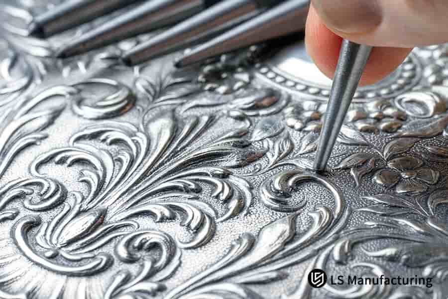
Figure 4: Hand embossing carves intricate patterns on silver decorative panel to 0.3 mm relief depth.
LS Manufacturing Sheet Metal Embossing Service For Medical Device Chassis Enclosures: Precision DFM And Cost Optimization
Precision sheet metal embossing is a deformation procedure which adds strength to thin gauge enclosures. LS Manufacturing used this process by limiting the DFM parameters to 3.5T (5.25 mm) depth and 2.5T (3.75 mm) edge clearance and sheet metal stress relief. This was done to counteract any internal forces and bring back the flatness from ±0.05 mm to ±0.01 mm on a 1.5 mm AL 5052-H32 chassis.
Client Challenge
The client is an OEM from Europe who needs a portable monitor chassis with a large area embossing. Warping was a major problem (flatness deviation to ±0.05 mm); cost was 245 RMB, defect was 14.2%, lead time was 13 days and it affected clinical compliance. The 14.2% defect and 13-day delay had the potential to affect the timing of your product launch due to regulatory issues. Lack of sheet metal die polishing contributed to wear and blurring of profile.
LS Manufacturing Solution
Gloria’s team developed a low temperature annealing process and changed the clamping sequence. The single strike depth was limited to 3.5T (5.25mm), emboss to bend clearance to 2.5T (3.75mm). Hydraulic nitrogen blank holder was used in the CNC hard die that was polished to a surface finish Ra 0.8 μm. Sheet metal forming optimization prevented crack formation in trial mold.
Results and Value
Joint alignment was attained at ±0.01 mm; cost reduced to 176.4 RMB (28%); defect level decreased to 2.1%; lead time reduced to 8 days (38%). All components were certified ISO 13485 and underwent 1,000 hours of salt spray tests according to MIL-A-8625 Type III (50 μm coating thickness). The 28% cost reduction and 38% reduced lead time allowed your team an early market access as well as a reduced sheet metal cost per part.
Takeaways
- Cap depth is 3.5T; maintain edge clearance of ≥2.5T.
- Perform stress relief annealing for work-hardened materials.
- Die polish should be of Ra 0.8 μm; use nitrogen blank holders for ±0.01 mm.
Data Source: LS Manufacturing medical device sheet metal project log (Project #MED-2026-8941, sample size >1,200). Salt spray test per MIL-A-8625 Type III (coating thickness 50 μm & 1,000-hour salt spray standard).
Dealing with warping beyond ±0.05 mm or 14.2% defects on your embossed medical chassis? Contact us for a DFM-optimized sheet metal quotation that delivers ±0.01mm flatness at 28% lower cost.

FAQs
1. What is the ideal material thickness for sheet metal embossing?
The normal range of thickness is from 0.5 mm to 3.0 mm; a thickness less than 0.5 mm will result in tearing of the material during forming, whereas a thickness greater than 3.0 mm increases the rate of die wear. LS Manufacturing provides precise control within the range of ±0.01 mm.
Data Source: ISO 2768-m tolerance standard
2. What is the maximum recommended embossing depth per single strike?
The maximum depth allowed per blow is 3 to 4 times the thickness of the material (3T–4T). Beyond that, the thinning and fracture of material may occur in the base of the embossed features. LS Manufacturing uses multi-blowing process to form embossings of deep depths without damaging the material.
Data Source: LS Manufacturing 2025–2026 empirical data
3. How far should an embossed feature be located from edges or bend lines?
Embossed parts need to be spaced 2 to 3 times the thickness of the material (2T-3T) from the bend edge line to avoid distortion and thinning of the metal. LS Manufacturing avoids distortions caused by bend edges through optimal spacing and progressive die sequencing.
Data Source: ISO 286 Limits and Fits system
4. How much does custom sheet metal embossing tooling cost?
The cost of hard matched tooling ranges from $2,000 to $10,000+ and is economical if divided among high-volume manufacturing quantities over 10,000 pieces. LS Manufacturing optimizes CNC tool die cutting and utilizes D2 tool steel to cut down tooling costs by 28%.
Data Source: LS Manufacturing tooling quotation logs
5. Which materials are best suited for deep sheet metal embossing?
Aluminum alloy like 3003 and 5052 and Low Carbon Steels have good ductility and elongation properties. Hence these are suitable for deep embossing without any cracking problems. At LS Manufacturing physical properties testing is done on all incoming materials so that the surface finish is maintained at Ra 0.8 μm.
Data Source: Machinery's Handbook, 31st Edition
6. How does LS Manufacturing manage springback in hard stainless steel embossing?
In order to control the springback of 304/316 stainless steel material, LS Manufacturing takes into account the over bending tolerance up to 2°- 5° and formability simulation in die design to maintain the tolerance of the part as ±0.01 mm using CMM inspection method.
Data Source: Zeiss CMM calibration report
7. Can soft tooling be used for low-volume embossing prototypes?
Yes. The polyurethane molds or 3D-printed flexible molds have the advantage of low capital cost and quick delivery time, thus suitable for testing purposes and design verification. The service from LS Manufacturing has proven to cut down on lead times by 38% compared to hard tooling techniques.
Data Source: LS Manufacturing 2025–2026 empirical database
8. How fast can I get a custom sheet metal embossing quote from LS Manufacturing?
Simply upload your CAD drawings in STEP or DXF format with material and quantity specifications, and LS Manufacturing's automated DFM system will provide a detailed technical assessment covering tooling feasibility and a transparent itemized quote within two hours.
Summary
Adherence to sheet metal embossing guidelines - material thickness 0.5mm-3.0mm, forming depth 3T-4T, edge clearance 2T-3T—will save you from any tearing problems and ensure control over the cost of the tools. LS Manufacturing, ISO 9001:2015/AS9100D certified company with decades of experience in precise work, will deliver cost-effective sheet metal products using its automated DFM.
Do you have problems with cracking in your embossing design or incorrect flatness? Too expensive tooling quotes? Click the quote button and upload your 3D/2D CAD drawings. Get a free DFM analysis and accurate quote in 2 hours from LS Manufacturing's engineers.
📞Tel: +86 185 6675 9667
📧Email: info@lsrpf.com
🌐Website:https://lsrpf.com/
Disclaimer
The contents of this page are for informational purposes only.LS Manufacturing servicesThere are no representations or warranties, express or implied, as to the accuracy, completeness or validity of the information. It should not be inferred that a third-party supplier or manufacturer will provide performance parameters, geometric tolerances, specific design characteristics, material quality and type or workmanship through the LS Manufacturing network. It's the buyer's responsibility.Require partsquotation Identify specific requirements for these sections.Please contact us for more information.
LS Manufacturing Team
LS Manufacturing is an industry-leading company. Focus on custom manufacturing solutions. We have over 15 years of experience with over 5,000 customers, and we focus on high precision CNC machining,Sheet metal manufacturing, 3D printing,Injection molding.Metal stamping,and other one-stop manufacturing services.
Our factory is equipped with over 100 state-of-the-art 5-axis machining centers, ISO 9001:2015 certified. We provide fast, efficient and high-quality manufacturing solutions to customers in more than 150 countries around the world. Whether it is small volume production or large-scale customization, we can meet your needs with the fastest delivery within 24 hours. choose LS Manufacturing. This means selection efficiency, quality and professionalism.
To learn more, visit our website:www.lsrpf.com
