 English



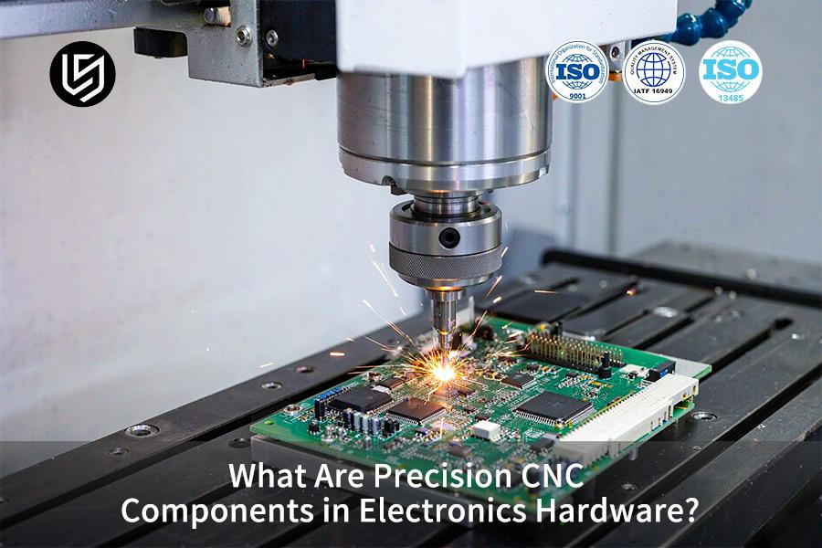
TL;DR: Precision CNC components in electronic hardware are machined structural components (enclosures, shields, and thermal blocks) manufactured through CNC (computer numerical control), also called subtractive manufacturing. Computerized manufacturing ensures accuracy as it involves cutting out solids rather than layering on them, and mating faces have tolerances of ±0.008 mm and take heat away from the sensitive circuitry.
Engineers and junior procurement specialists will get exposed to device architecture before venturing into any machine shop. First common error that they can make is thinking that metal by itself will prevent EMI (electromagnetic interference — unwanted radiated energy that disrupts nearby circuits) because only seams that are completely sealed can prevent EM interference and not just bulk metal.
Key Takeaways
- Precision CNC electronic component structures are made by machining. CNC machining machines remove material from solid stock and do not deposit material. Housings have to handle loads that could crack bare circuit boards, and metal walls block shielding of electromagnetic interference.
- Metal enclosures conduct heat away from processors better than do polymer enclosures. Surface finish imposes a strict thermal constraint: peaks higher than Ra 0.8 μm create insulating air micro-gaps. If a face is made to Ra 0.8 μm — Ra is the mean height of surface peaks, then heat can only travel through thin air gaps.
- Hardware tolerances exist in two classes. Structural holes allow ±0.02 mm. Mating faces of RF cavities require a tighter class cited above because the RF energy is confined not by bulk but by continuous seams.
- Thin-wall enclosures warp when cutting heat conducts into the workpiece faster than the evacuated chips can carry it away. Milling of 7075-T6 (T6 = solution heat-treated and artificially aged)) aluminum alloy at Vc 60 m/min — Vc (cutting speed), keeps the heat input low. Cutting speed governs distortion in this case.
Why Trust This Beginner's Guide?
Gloria boasts 15+ years of experience in precise engineering and rapid prototyping when it comes to teaching electronics hardware. Gloria's DFM (design for manufacturability) tips clarify why part geometry should fit the tool used before the drawings get designed. Follow Gloria's Engineering Insights on LinkedIn features her machining guides for beginner hardware teams.
Society of Manufacturing Engineers (SME) Education Resources, 2024 educational material provides instruction on metal cutting for computer numerical control operations, while ISO 286:2010 defines tolerance classes for mating dimensions. Dimensional statements are supported by inspection reports and materials certificates issued from ISO 9001-certified facilities.
Apprentice engineers and entry level buyers often believe that a tighter callout automatically results in better electronics performance. The inspection time and fixturing required increases with each additional tight callout, cosmetic surfaces seldom require tight bands. Simply put, tight bands go where there is heat and electronics.

What Is CNC Machining For Electronics And How Does It Function?
CNC machining for electronics is a material-removal process where enclosures, cavities, and mounts are machined from a solid billet on pre-programmed tool paths. Instructions programmed on a machine control system guide milling cutters and turning tools along the metal or engineering plastic stock. Multi-axis motions allow operations on several faces in one clamping operation; thus, deep cavities, micro channels, and snap-fit datums have one origin.
Features having shared origins lie within a 20-micron band according to Groover, Fundamentals of Modern Manufacturing, 7th ed., ch. 21. Multi-axis CNC machining suits low-volume trials and high-end devices, while high-volume thin-wall plastic stampings fall outside the economic range.
What is CNC machining for electronics? As a topic, CNC machining for electronics covers both the cutting process and the motion of the machine tool. This machine motion, in turn, is divided according to the number of axes: 3-axis, 4-axis and 5-axis.
- 3-axis machining centres cut in X, Y and Z directions; the side walls require a second setup (clamping of one workpiece) where each new setup defines new datums.
- Multi-axis machines change the angle of the spindle or table to access the undercut walls within one setup.
- Precision CNC components in electronics hardware begin as CAD walls that CAM software turns into G-code (numbered instructions for axis position, feed and spindle state).
G-code is different from CAD geometry because the latter describes the form of the part, while G-code describes the movement of the cutter. How does CNC machining work depends on the instruction file, not on the model.
Novice engineers mistakenly believe that five axes alone ensure tight tolerances. The number of axes increases range, stiffness, deflection, and thermal expansion determine the tolerance.
CNC tolerances for electronics hardware have one common denominator: Tight tolerances apply only to radio-frequency mating faces and thermal contact faces.
Injection molding outperforms multi-axis CNC machining in cost for thin plastic clips; however, walls of injection molds contract unevenly. Simply put, motion control dictates the reachable faces; stiffness controls how accurately the cut features get there.
What to Remember
- Machined enclosures derive from solid billet; sheet or molded materials use other methods.
- Single point of origin ensures greater accuracy than multiple setups.
- Number of axes increases range; stiffness and deflection determine the dimensional tolerance.
Source of academic principles: The chapter on the mechanisms of precision in metal subtractive manufacturing from Groover's *Fundamentals of Modern Manufacturing*.
Related keywords: electronics CNC machining basics / multi-axis machining explained / CNC machining accuracy limits
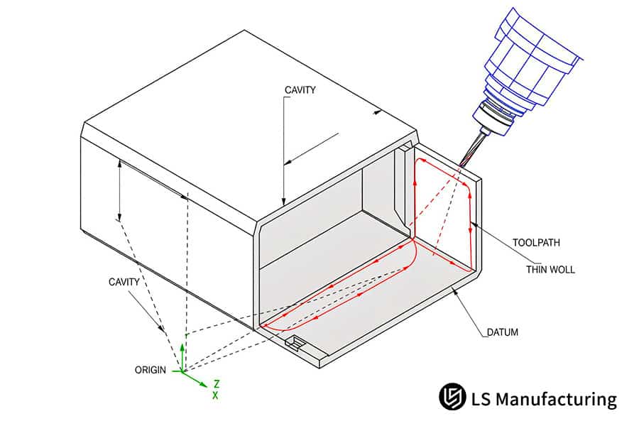
Figure 1: Cross-Sectional Diagram of a Multi-Axis Milled Enclosure and Internal Toolpath Vectors
Why Electronics Hardware Requires Precision CNC Machining Today?
Electronics-grade precision CNC machining is the act of machining metal walls to the dimensions necessary for the signals and heat that need them, solving RF leakage at the seams via conductive path continuity. Increasing chip power and increasing carrier frequency reduce the dimensional tolerance allowed for the housing. Two physical limits explain why electronics hardware requires CNC machining.
Shielding Seams at Radio Frequency
A shield operates by completing a conductive circuit, not by mass. RF (radio frequency) energy leaks out of any seam tolerance and the seam emits radiation when its length approaches a fraction of the signal wavelength. CNC thin wall machining handles walls too thin to resist tool pressure.
CNC tolerances for electronics hardware differentiate by use: the default band applies to general surfaces while RF cavity surfaces get the tighter class. Milled flanges maintain seam gaps in the single-digit-micron band.
Where Heat Leaves the Package
A processor die passes hea into the base only at points of metallic contacts due to the inefficiency of air in comparison to aluminium at transferring heat. Surface valleys of milled contact surfaces are flattened up to a micrometre. Precision CNC components in electronics hardware field-seal and transfer heat.
Related keywords: electronics CNC machining limits / RF enclosure seam tolerance / thermal contact flatness basics
Basic Comparison Table
Forming process and physical function distinguish between four commonly found electronic structures. Material selection is dictated by application function, which means that CNC milling combines RF shielding parts and thermal parts with distinct metals. Newbie engineers can match the accuracy band of each part to a corresponding physical application like either seam sealing or heat transfer.
| Component Type | Typical Material | Core Physical Principle | Typical Machined Accuracy |
| RF Shielding Cavity | 6061-T6 aluminium | Continuous conductive barrier blocks | EMI radiation Precision grade ±0.008 mm |
| High-Efficiency Cold Plate | C11000 pure copper | High thermal conductivity moves junction heat | Precision grade Ra 0.8 μm |
| External Protective Enclosure | 7075-T6 aluminium | High yield strength resists impact and twist | Standard grade ±0.02 mm |
| Connector Isolation | Standoff POM polyoxymethylene plastic | Low dielectric constant prevents pin shorting |
Standard grade ±0.02 mm |
Inner shielding and heat conducting parts require precision grade machining with an accuracy of ±0.008 mm; outer frames allow a tolerance of ±0.02 mm for strength – basically, tighter bands go along with fields and heat.
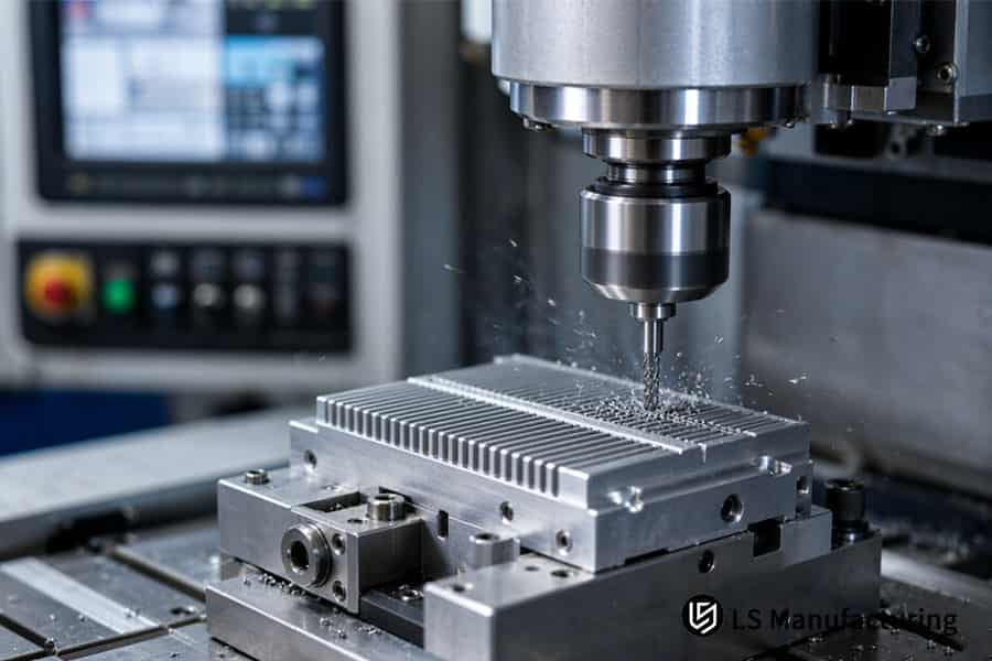
Figure 2: Precision machining cuts parallel fins into a metal heat sink block, sending fine chips past the fixture.
How Precision CNC Milling Shapes Electronic Housings And Shields?
CNC machining for electronic housings, or computerized numerical control cutting, removes material progressively along a programmed toolpath, in which a rotating end mill moves according to programmed spatial trajectory. Each pass removes a layer, hence wall shape follows that spatial trajectory. How precision CNC milling shapes electronic housings depends on direction of cut and layer sequence.
Climb milling (cut in which rotating tool goes with the feed, thereby creating thin chips during each cut) is used for machining RF shield housing (which is quite thin), pushing cutting pressure onto the worktable. Uniform pressure results in equal residual stresses on both sides of walls, which ensures that walls will not spring back after releasing clamps.
Cavity Roughing and Stress Allowance
Types of CNC machined electronic enclosures have various cavity depths. Deep RF cavities require steps for roughing, shallow cover cavities require face milling only. CNC machining deformation control starts here, as relaxed part will retain its shape for finishing.
Finishing Uniform Walls
Finishing establishes wall thickness. Multi-flute end mills allow running with light feeds, allowing achieving uniform walls up to 0.8 mm thick without any chattering marks. Precision CNC components in electronics hardware become a key requirement here, as uniform walls will cut uniform chips. Inspection is performed according to the following standards: ISO 2768-m (ISO 2768-1:1989) deals with dimensional tolerance, and ASME Y14.5-2018 with geometrical tolerance. Dimensional tolerance and form tolerance are different questions, so the shielding drawings require both.
New engineers always assume that one good finishing pass will determine wall accuracy. Accuracy is achieved through stock uniformity – an uneven roughing allowance results in one side cutting larger chips than the other, which causes deflection of the cutter. An apprentice should realize that stock uniformity is more important than a finishing pass. CNC machining process basics begin with roughing, after which an apprentice familiar with shield drawings will be able to determine whether wall uniformity or tolerance band is the cause of the callout.
Transferable Lessons
- Roughing determines geometry; finishing is just refinement of existing stock.
- Climb milling provides stability for thin walls; press brakes work better for large volumes of flat sheet metal.
- ISO 2768-m and ASME Y14.5-2018 address dimensional and geometric problems separately.
Standard references adopted: Inspections for dimensional tolerances and geometric characteristics are based on ISO 2768-m and ASME Y14.5.
Related keywords: electronics enclosure milling / CNC shield box machining / thin wall milling limits
How CNC Machined Heat Sinks Work Inside Compact Hardware?
The core principle of CNC machined heat sinks is area creation plus base flatness, because heat crosses metal far faster than it crosses air. Fins that have been milled increase the surface that the air stream or liquid comes into contact with. Base flattening eliminates the peaks that keep the die separate from the metal.
In CNC machining or milling, fins and base are cut in one clamping, therefore, making the fins perpendicular to the mounting surface. Machined heat sinks are suited for compact and high-power compute modules, where forced air remains fast and channels in the fins remain narrow.
How CNC machined heat sinks work becomes evident once the resistance path breaks down into three segments:
- Conduction Resistance — base thickness and alloy conductivity transport heat from die to fins.
- Contact Resistance — micrometre deep valleys in the interface retain air, and air retains heat.
- Convection Resistance — fin surface area and air velocity transfer heat to the coolant.
Contact resistance dominates the transient response. Polishing the base reduces the startup pulse, since there is no insulating layer in the valleys anymore.
What materials are used in CNC electronics determines the location of each resistance. C11000 copper conducts the heat better than aluminum and can be machined into high density pin fins. Aluminum 6061-T6 is much lighter and is suitable for weight-critical frames. Precision CNC components in electronics hardware combines both materials on one common mounting face.
Milling of the copper pin fin requires a minimum feed per tooth. Machinery's Handbook (31th ed.) talks about the copper alloy pin fin milling. C11000 metal smears when rubbed against the cutting tool, not when sheared. Rubbing flank will heat the newly formed pin. Thicker pins help only when convection — not conduction — limits the thermal path.
Young engineers can also then go through a thermal specification and determine whether the limiting factor is either the base or the flow of air. In layman’s terms, fins transfer heat to the air while flatness transfers heat to the fins.
Bottom Line
- Fins overcome convection resistance while flatness overcomes contact resistance.
- Copper conducts heat quickly while aluminum reduces weight.
- Small high-power modules benefit from machined heat sinks more than other types.
Source: *Machinery's Handbook* (31th Edition)—guidelines on feed rates for milling copper alloy heat sink fins.
Related keywords: CNC heat sink machining / machined fin thermal path / copper heat sink milling
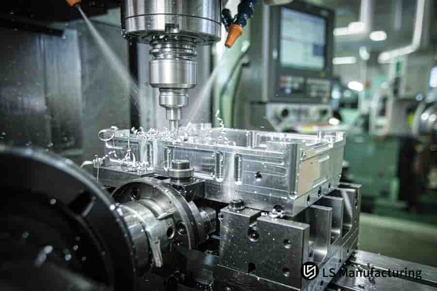
Figure 3: Computer numerical control mills slots into a clamped metal housing while coolant washes away loose chips.
What Materials Are Used In CNC Electronics For Optimal Stability?
Electronics CNC machining material selection is a balancing act between thermal conductivity, shielding and thermal stability. Aluminum 6061-T6 and 7075-T6 dominate structural enclosures. Both types of aluminum offer a strength to weight ratio along with protection from corrosion. Polymer engineering plastics like POM and PEEK form the insulating housing for live pins. Expansion mismatch determines maximum mixed metal fits. Expansion mismatch, not strength, answers what materials are used in CNC electronics.
Aluminium and Copper Roles
6061-T6 combines light weight with good machinability and effective EMI reflection; RF cavities and brackets use 6061-T6. Aluminium 7075-T6 provides greater yield strength in thin shells. C11000 copper is typically specified for cold plates and busbars because copper conducts heat better than both aluminium grades. CNC machining alloy selection begins with load path and heat path, not habit. Expansion mismatch between stacked alloys explains why electronics hardware requires CNC machining in place of casting.
Polymers and Thermal Expansion
POM and PEEK insulate pins at different potentials and retain tight holes. Polymer billets expand much more per degree than metal, thus allowances in press-fits account for mismatch of thermal expansion between mating parts. Precision CNC components in electronics hardware pair metal frames and plastic stand-offs on one mounting surface.
Cutting Speed and Stress Relief
In thin 7075-T6 shells, a moderate cutting speed limits the heat entering the wall, as per LS Manufacturing application engineering information. Precipitation hardened zones in 7075-T6 are resistant to cutting tools, therefore a range of cutting speeds with flooded coolant prevents BUE (built-up edge, welding work material on cutting edge). Welded lump affects rake angle and wall surface destruction. High-speed processing directs heat into thin walls rather than chip and retained heat reduces temper that was created previously. CNC machining heat stability relies upon the process sequence rather than speed of a spindle.
- Roughing – first; stress-relief annealing – second; finishing – last.
- Composite stacks consist of an aluminum frame with a copper plate, hence fit allowances depend upon working temperature.
Engineers in their beginners' stage always put stress relief as a late process operation. Relaxation after finishing displaces walls which were just finished.
Points to Keep
- Aluminium provides structure; copper provides heat; plastics insulate.
- Stress relieving should happen between roughing and finishing, not after finishing.
- Differential thermal expansion determines fit allowances in multilayer assemblies of different metals.
Related keywords: electronics CNC machining materials / CNC machining thermal expansion / CNC machining alloy stability
How 7075 Alloy Machining Works In Practice: A Semi-Hardware Example From LS Manufacturing
CNC machining of 7075-T6 aluminium is a controlled removal process that converts pre-stretched bar stock into thin-wall enclosures for electronics. An entrepreneurial edge-computing company required a robust automotive control box with high-frequency boards in a tight package. Using pre-stretched 7075-T6 allows CNC machining of 7075-T6 without distortion due to stress relief by stretching prior to machining. Stress sequence, not spindle speed, determines the survival of micron-level thin-wall parts through finishing process.
How does CNC machining work in thin-wall electronics thus begins with the state of the stock. Small high-power control boxes require machined enclosures; high-volume flat control boxes require press brakes.
Application Scenario
Automotive control boxes deep cavity walls were set to be 1.0 mm thick. RF cavity cover seams had to be within ±0.008 mm range due to tight electromagnetic protection requirements. Young engineers believe that the spindle speed alone is responsible for wall geometry. Dimensional control comes after stress release.
Principle in Practice
Vc = 60 m/min worked well for 7075-T6 as the precipitated phases wear the cutting edge quickly. Higher feeds cause the heat to penetrate walls, and the retained heat reduces the just-cut temper. Roughing was performed first; natural aging (room temperature rest to reduce stress) relieved stress prior to finish machining with the diamond-coated tools to Ra 0.8 μm. CNC machining tolerance standards separate dimensional and form controls.
Results and Insights
The warping of deep-cavity parts stems from the release of residual stresses after finish machining; To put it briefly, frozen stress sequencing rather than faster spindles determines whether micrometre-class walls will retain geometry.
Data source: LS Manufacturing manufacturing database record (Project #SEMI-2026-804, sample size >800 electronic structural parts); statistical scope: 2025–2026 measured plant-wide records.
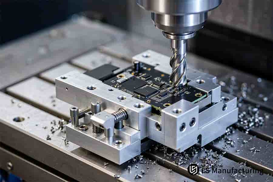
Figure 4: A drill bit bores a black circuit board locked in a bolted fixture, leaving chips around the clamps.
FAQs
1. What is the main difference between CNC-machined electronic parts and stamped sheet metal?
CNC-machined electronic parts are machined from solid billets, and material removal allows deep pockets, thick walls and rigid fins to share the same piece. Sheet metal stamping bends uniform thin blanks, and keeps formed size tolerances within ±0.1 mm, according to LS Manufacturing process documentation and ISO 2768-1:1989. Junior engineers pair CNC machining applications to part geometries: deep pockets require milling, and thin blanks are ideal for press brakes.
2. How do you decide which tolerance to call out on an electronics housing?
Dimensional band is one permissible size range for one feature, separate from form controls that specify shapes; each tight band increases fixturing and inspection steps. RF mating surfaces and thermal contacts between the chip and the housing, while the exterior surface of the housing requires ±0.02 mm, documented in LS Manufacturing process documentation under ISO 2768-1:1989. Procurement departments allocate tight bands to surfaces where fields or heat pass.
3. How does 6061 aluminum suit electronics enclosures?
Aluminium 6061 reflects incident EMI via electrical conductivity., and high thermal conductivity, according to property data in ASM Handbook Vol. 2. According to LS Manufacturing process notes, they use together such tolerances with general tolerances of ISO 2768-1:1989. Design reviewers balance mass, shielding and heat flow across CNC machining materials before naming one alloy.
4. Can CNC machining handle low-dielectric plastic insulators for circuitry?
Low-dielectric insulators consist of polymers that reduce parasitic capacitance and crosstalk., and POM and PTFE serve to insulate pins operating at different potentials. Milled POM and PTFE are ±0.02 mm for LS Manufacturing according to process guidelines, and ASTM D150-18 regulates dielectric constant measurement of such plastics. In simple terms, junior engineers subsequently differentiate insulation-based and fit-based polymer designations.
Summary
Metal components machined are used to seal the conductive pathways from stray fields and dissipate heat from the active die in electronics hardware. While the outer enclosure is made of dimensional classification, the RF connector uses tighter tolerance band, and grain size, cutting stress, and surface finish determine dimensional transitions.
Precision Electronics Machining Insights Desk
Multi-cavity enclosures tolerance band allocation and thin wall clamping rigidity provide young engineers an effective revision avenue. Thin wall clamping, tolerance band, and micro-fine thermal questions can be directed to LS Manufacturing at +86 185 6675 9667 or info@lsrpf.com. You may also visit our official engineering knowledge hub to review detailed application standards for GD&T (Geometric Dimensioning and Tolerancing).
Further Reading: CNC Milling Services For Electronics: Solving Precision & Speed Challenges

