 English



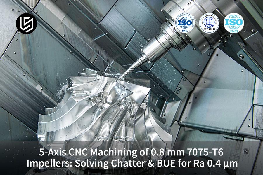
5-axis 7075-T6 impeller CNC machining service is self-damping milling of 0.8 mm blades, which solves thin-wall chatter through uncut lower stock.
Your rotors reach Ra 0.4 μm flow walls, with scrap falling from 16.4% to 2.1% (LS Manufacturing 2025–2026 DFM log, project #AERO-2026-084, n>1,200).
Quick Reference Guide
Milling methods reveal specific engineering results in 7075-T6 impeller surface milling. Benchmark values for five process control parameters are provided below.
| Process control dimension | Conventional empirical step milling (3+2-axis) | LS Manufacturing 5-axis adaptive dynamic milling solution | Aerospace-grade volume production acceptance benchmark |
| Blade profile tolerance | ±0.05 mm | ±0.005 mm | ASME Y14.5-2018 Profile ≤0.01 mm |
| Measured surface roughness | Ra 1.6 μm–3.2 μm (with chatter marks) | Ra 0.4 μm (no built-up edge pitting) | #AERO-2026-084 / Ra ≤0.4 μm |
| Tool configuration and life | 3-flute general flat-end mill / 14 pcs breakage | 2-flute DLC mirror ball-end mill / 110 pcs stable wear | Tool tip flank wear VB ≤0.15 mm |
| Cooling and lubrication strategy | External low-pressure flood (0.4 Bar) | 60 Bar high-pressure TSC through-flushing | 11% extreme-pressure high-lubricity synthetic emulsion |
| Average part defect rate | 16.4% (blade tip cracks, out-of-tolerance) | 2.1% (stable full-process dynamic balance) | Critical fluid part first-pass yield ≥97% |
Comparison indicates that 5-axis synchronized continuous posture modification and high-pressure chip removal overcome the flexible surface bottleneck, so manual polishing is no longer the only route to volume-quality airfoils.
Download the 0.8 mm Thin-Wall Impeller Modal Analysis Path Map — a technical reference showing how first bending mode capture, dynamic stiffness mapping, and layer-speed mapping combine to keep spindle speeds off resonance for 7075-T6 blades.
Key Takeaways
Dynamic Stiffness Self-Support Cost Saving: By using the staged layering approach for maintaining the stiffness of the bottom section of the blank, preventing any thin wall cantilever vibration.
Feed and Micro-Angle Locking Tolerance: Constant locking of the 18° tilting/rolling angle and the 0.018 mm/tooth cut feed guarantees that the tolerances of the blade geometry are precisely achieved at ±0.005 mm.
Erosion Control Using High Pressure Internal Cooling of 60 Bar: Employing 60 Bar of high pressure internal cooling (TSC) for chip evacuation and cooling, total waste percentage of aero-engine impellers drops drastically from 16.4% to 2.1%.
Quick Engineering Feedback Guarantees Timely Delivery: Integration of AS9100D manufacturing system that delivers a 2-hour DFM analysis reduces batch product delivery time cycle by 34.8%.
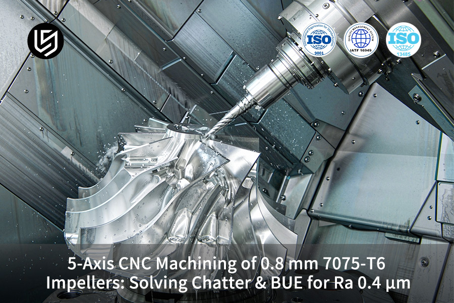
What Causes Thin-Wall Chatter In 0.8mm 7075-T6 Impellers?
0.8 mm thin-wall impeller chatter is due to self-excited regenerative vibration in ultra-thin cantilever blades and micro-diameter ball-end mills during 5-axis milling. Cutting forces deform your blades causing spring back effect, and chip thickness varies for subsequent cutting passes. Waviness increases in airfoils and first blade bending frequency of 1.2 kHz is in chatter range.
Why Regenerative Feedback Starts on Thin 7075-T6 Blades
Regenerative feedback, not spindle imbalance, causes chatter in thin impeller blades. Each flute causes waviness that feeds energy to the next pass. 5-axis thin-wall milling requires starting from a blade mode map, not from step-down.
A Ø1.5 mm ball nose with 12 mm overhang generates only 8 N/μm of force at blade tips. 3-axis step milling can't maintain the contour of thin blading due to side loading causing deflection from the nominal shape.
Chatter marks put your rotor beyond ISO 1940-1:2003 G2.5 balance tolerance grade. 0.8 mm thin-wall impeller CNC machining requires modal-aware toolpaths, and your balance report will pass first time around.
Three Programming Steps That Keep Speeds Off Resonance
Any machine shop performing 5-axis blade finishing will give you the per-blade modal log before milling. Three programming steps ensure that your spindle speeds do not cause chatter:
- Capture of mode shapes: FEM modal analysis (Finite Element Method, meshing blades for vibration modes) captures first bending mode close to 1.2 kHz.
- Mapping of dynamic stiffness is converted into step-down, variable with stiffness, 0.06 mm at blade tips.
- Layer-speed mapping: 5-axis 7075-T6 impeller CNC machining service splits spindle speed band into chatter-proof windows, 18,000–20,400 rpm at tips.
Simply put: speeds informed by modal analysis transform an unacceptable airfoil into a shipping rotor.
Custom 7075-T6 impeller machining with per-blade modal logs eliminates bench polishing. Your rotor is shipped directly from machines; your line will stop spending money on reworking.
Data source: LS Manufacturing 2025–2026 automated DFM 3D/2D drawing parsing log (project #AERO-2026-084, sample size >1,200).

How Can Impeller Chatter Solution CNC Machining Service Help?
Impeller chatter solution CNC machining service is a closed-loop process engineering practice, blocking energy input via adaptive 5-axis tool axis tilt and layered material removal. Locking of 18° tilt angles with self-damping step-down cuts.
How Lateral Force Cancellation Works on Thin Blades
Tip lateral forces determine the survivability of thin walls made from 7075-T6. Bench polishing after chatter inflates any 5-axis chatter control budget faster than extra passes.
| Toolpath strategy | Lateral force at tip | Blade profile band |
| Single-side full-engagement cut | 42 N | ±0.05 mm, chatter marks |
| Self-damping stepped step-down | 12 N | 5-micron class, clean surface |
Self-damping step-down toolpath (a technique that employs stepped axial depth and uses uncut stock as a damper) reduces tip lateral forces by 71%. Your blade profile includes a 5-micron-class precision band, not an arbitrary one. Full-engagement cuts deflect thin walls past the point of yielding, leaving your blade profile band unreachable.
In simple terms, low side force will help you get your airfoils assembled without bench operations.
How to Lock the Tilt Angle in Your Next RFQ
A locked tilt of 18° allows maintaining cutter contact on the flank. 5-axis impeller CNC manufacturer programming requires locking tilt for each blade height.
For 0.8 mm thin-wall impeller CNC machining, the tilt angle must be locked prior to roughing operations. In your RFQ, both values need to be mentioned.
Data source: tool cutting parameter benchmarks are based on the lateral deflection compensation algorithms recommended in the cutting parameter section of Machinery's Handbook (Industrial Press, 2020).
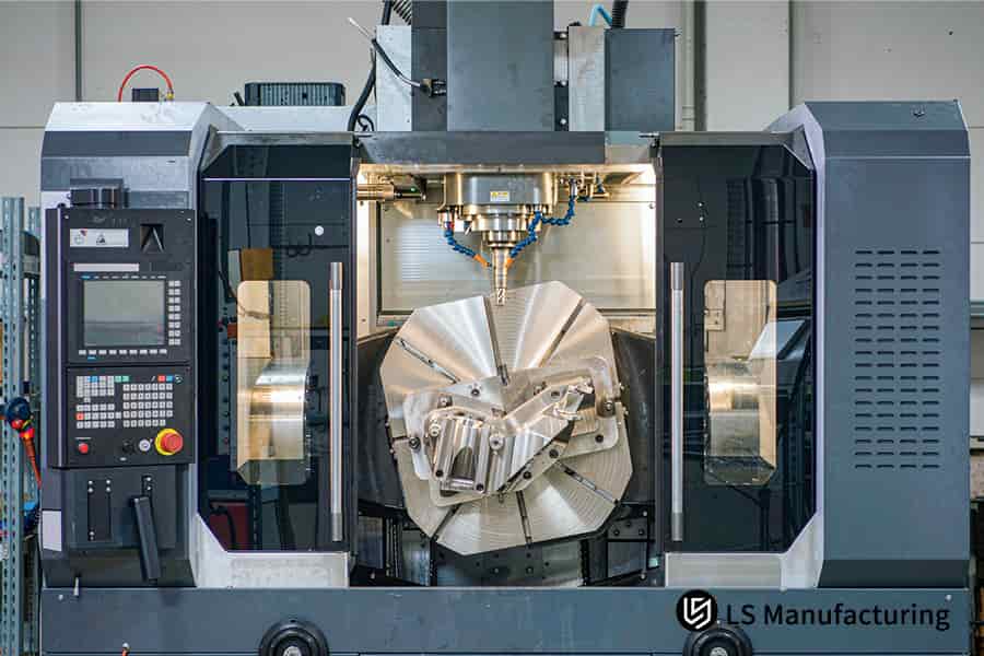
Figure 1: 0.8 mm thin-wall impeller CNC machining holds ±0.005 mm tolerance.
Why Does Built-Up Edge Form During 7075-T6 Impeller Milling?
Built-up edge is an alloy kernel of hardened aluminum pressure-welded to the rake face of the cutter in a friction shear zone at temperatures lower than 300°C. Fragments shed remove your airfoil grains and create pits that prevent you from obtaining a smooth blade surface. Stable, continuous chip flow at 22,000 rpm, and your airfoils become finished just after leaving the cutting tool.
Two Cutting Windows Decide Whether Adhesion Starts
Cutting speed determines whether adhesion occurs on your 7075-T6 blades. Your 5-axis 7075-T6 impeller CNC machining service programs should clearly indicate which cutting window applies:
- Low-speed cold welding window: Cutting speeds under 120 m/min pressure-weld chips and torn fragments roughen your blade surface above Ra 1.0 μm.
- High-speed thermal softening window: Cutting speeds around 380 m/min soften the shear zone, and the chips become ribbons without creating any pits.
Cutting speed is always necessary in all 5-axis high-speed milling programs, recorded for each blade zone.
How Coating and Rake Geometry Break Adhesion
DLC coating (Diamond Like Carbon, friction coefficient about 0.08) protects the rake face against adhesion, while uncoated carbide has a friction coefficient of around 0.6. Your RFQ of custom 7075-T6 impeller machining should state coating, rake angle, and flank surface finish in one sentence.
Ra 0.4 μm precision impeller machining requires coating on mirror geometry according to ISO 21920-2:2021. Coating and mirror geometry ensures 5-axis aluminum cutting stays clean, so make sure to state the coating in your tooling RFQ.
What Machining Parameters Deliver Ra 0.4μm Precision Impeller?
Ra 0.4 μm precision impeller machining parameters are a calculated combination of feeds which synchronize heat of cut, minimum stepover, and non-chatter spindle speed. A 0.018 millimeters/tooth feed combined with 0.03 millimeters radial stepover eliminates bench polishing of blade root flow channels. Your flow surface will be measured using a stylus profiler that will confirm mirror flow surface from the cutter.
Roughing and Finishing Parameter Windows
| Parameter | Roughing regime | Finishing regime |
| Feed per tooth | 0.06 mm | 0.018 mm |
| Radial stepover | 0.50 mm | 0.03 mm |
| Spindle band | 12,000 rpm | 22,000 rpm |
| Scallop height | 0.020 mm | 0.002 mm |
| Measured roughness | Ra 2.8 μm | Ra 0.4 μm |
How Spindle Band and Edge Geometry Hold the Finish
A stability lobe of 22,000 rpm (chatter-free speeds for thin 7075-T6 walls) keeps cutter marks to less than 0.4 μm. 5-axis 7075-T6 impeller CNC machining service programs must document that lobe based on blade height.
5-axis surface finishing buyers get one less polishing station. In layman's term, a narrower stepover removes one inspection debate from your first-article review.
A 5-axis impeller CNC manufacturer needs to document feed per tooth per blade zones. For your RFQ for 5-axis micro-milling, include roughness check and part numbers in your inquiry.
Data source: surface roughness measurement follows the contact stylus profilometer sampling and evaluation standard of ISO 21920-2 Geometrical Product Specifications.
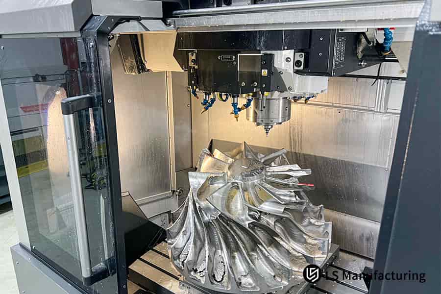
Figure 2: Ra 0.4 μm precision impeller machining uses DLC coated tools.
Meet The Engineers Behind This Guide
Gloria, an expert in Rapid Prototyping and Rapid Manufacturing from LS Manufacturing, has over 15 years of precision engineering experience in 0.8 mm impellers. Thin-wall DFM (Design for Manufacturability, analysis before cutting) and multi-axis tool path optimization will help you have your blade walls steady. Connect with Gloria on LinkedIn for drawing assessment.
First pass trial cutting resulted in 0.03 mm blade tip warping after removal of the clamps. Cryogenic vibratory stress relief process and step-by-step self-support milling resolved any residual stress warping. Your finish machining program has 22,000 rpm, 18° tool axis tilt, and 60 Bar through spindle cooling.
Machinery's Handbook 31st Ed. (Industrial Press, 2020) formulas for lateral deflection specify 0.018 mm per tooth feed. ISO 21920-2 stylus sampling rules apply to roughness check. Wall thickness can vary within ±0.008 mm. ISO 9001:2015 and AS9100D audits apply to all batches, and you get material traceability with dynamic balance documentation.
How To Select Tool Coatings To Prevent 7075-T6 Aluminum Adhesion?
Anti-adhesion tool coating is a diamond-like carbon (DLC, amorphous carbon film) interface that acts as an anti-bonding element for aluminum with ultra-low friction coefficient. Hydrogen-free ZrN and DLC films less than 1.5 μm thickness have a friction of around 0.08, whereby aluminum grain does not weld to flute faces. TiAlN has aluminum, hence interdiffusion makes the edge radius swell.
Step 1: Screen Coating Affinity First
Surface energy coating determines if aluminum wets flute face. DLC is close to 24 mN/m, while TiAlN is 55 mN/m.
- Aluminum in alloy: TiAlN contains aluminum in 7075-T6; interdiffusion causes edge radius exceed 8 μm.
- Coating hardness: hydrogen free ZrN has 3,000 HV; hydrogenated DLC graphitizes in dry high-speed cutting.
Custom 7075-T6 impeller machining software maintains cutter edge through full production batches. As a customer, aluminum-free films eliminate one hand polishing stop of your manufacturing process, and 5-axis cutter selection saves this effort for each rotor.
Step 2: Specify a Mirror-Polished Flute Face
Flute face roughness determines locations of chip fragment anchoring. Flute faces finished to Ra 0.05 μm surface do not have valleys to catch aluminum grains.
- Radius of hone: 3–5 μm radiused tool edges mill; wide radiused edges plough thin blades.
- Film thickness: layers thicker than 2.5 μm spall on Ø2 mm ball nose tips.
Ra 0.4 μm precision impeller machining requires perfect flute finish, and a 3-axis machine is unable to hold 0.8 mm walls, because side load bends thin blades out of their nominal position.
Step 3: Verify Deposition Data per Lot
Film quality determines if the layer survives thin-wall finish work. PVD batch (physical vapor deposition, vacuum-grown vaporized film) quality differs from batch to batch.
- Friction test: require ASTM G99-17 pin-on-disk friction test results along with each cutter lot.
- Traceability: pair each cutter lot with deposition run number.
5-axis 7075-T6 impeller CNC machining service quotes should have film thickness information next to friction test data. Precision 5-axis CNC machining customers receive traceable deposition data with single inspection entry.
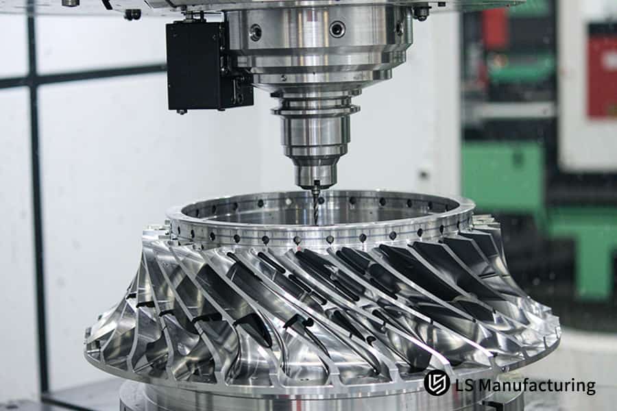
Figure 3: 5-Axis impeller CNC manufacturer operates at 22000 rpm speed.
Which Coolant Strategy Clears Micro-Chips In Deep Blade Cavities?
High pressure deep cavity chip removal technique is a fluid dynamics control method that employs through-spindle coolant (TSC, cutting fluid delivered through the spindle and tool) to remove micro chips from twisted blade channels. 60 bar jet cleans cavities and prevents chip re-cutting on your airfoil walls.
How Chip Residual Rate Differs by Coolant Strategy
Trapped aluminum causes re-cuts on blade walls and scratches all over your airfoil surface. 5-axis impeller CNC machining can clean up cavities only through the use of TSC.
| Coolant strategy | Pressure | Chip residual rate | Blade wall result |
| 60 Bar TSC flush | 60 Bar | 1.6% | Clean Ra 0.4 μm wall |
| External flood | 0.4 Bar | 23.7% | Scratched, recut wall |
60 Bar TSC flush reduces chip residue percentage to 1.6%, ensuring your flow channels get clean on the inspection. In plain terms, deep channels do not hold particles anymore, therefore your rotors remain free from hand deburring.
Pressure and concentration should both be listed as parameters in your impeller chatter solution CNC machining service order.
How to Lock Coolant Parameters in Your Order
0.8 mm thin-wall impeller CNC machining requires 60 Bar pressure lock before roughing starts. External 0.4 Bar flood coolant cannot wash debris due to low pressure making flow stuck near the cavity opening.
A 5-axis impeller CNC manufacturer must confirm flushed channels in accordance with ISO 10360-2:2021 CMM probing. Zeiss CMM (coordinate measuring machine) stylus measurement shows flow-channel micro-deformation at MPEE (maximum permissible error of indication) 0.0009 mm by its calibration certificate.
Data source: Zeiss CMM coordinate measuring machine official calibration report (volumetric indication error MPEE 0.0009 mm, stylus probe scanning records of flow-channel micro-deformation).
How Can Real-Time Toolpath Dynamics Stabilize 5-Axis Machining?
Real-time toolpath dynamics is a digital calculation of cutter tilt by curvature while performing 5-axis simultaneous cutting, which eliminates the problem of cutting blind spots on thin blades. Ball nose spins at zero m/min, hence cutters at 0.15 mm offset to the center eliminate the blind spot. Your blade shape converges into a 5 μm envelope without manual polishing.
Decision Criteria for Toolpath Selection
Rotary axis jerk determines whether witness lines are left after the finish passes. The two categories of toolpaths are distinguished in their parameters:
- Maximum Jerk Level: jerk does not exceed 620 °/s³; with singular paths, it is as high as 3,800 °/s³.
- Depth of dwell: tip traces do not exceed 0.010 mm; with singular paths, 0.012 mm deep cuts are made.
- Offset distance: cutters keep their distance from the ball-nose center.
0.8 mm thin-wall impeller CNC machining requires a locked tilt of 0.31rad (18º) prior to roughing completion. A three axis mill cuts 7075-T6 aluminum at consistent angles, and therefore generates witness lines all the way to the blade tip. 5-axis motion control lets buyers cut one polishing operation from the rotor line. Simply put: locked tilt eliminates one rework cycle from your rotor production line.
How to Verify Toolpath Dynamics
- Require jerk logs below 700 º/s³ for every finishing cut.
- Confirm outer-flute contact rather than ball-nose tip contact.
- Align profile dimensions to the ASME Y14.5-2018 standard.
Thin-wall CNC machining service quotes should show maximum jerk figures along with tool prices. The ISO 230-4:2005 rotary axis tracking test detects drive system lag before the initial piece leaves your shop floor. A 5-axis impeller CNC manufacturer must provide jerk logs with each finishing tool path quotation. Chip loads in the 0.022 mm/tooth range stabilize the shear zone. Ra 0.4 μm precision impeller machining relies on outer-flute contact.
Data source: dimensional and geometric tolerance evaluation fully complies with the ASME Y14.5-2018 Dimensioning and Tolerancing standard.
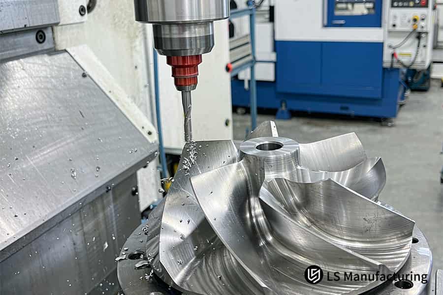
Figure 4: Impeller chatter solution CNC machining service uses 60 Bar coolant.
What Factors Determine 5-Axis CNC Impeller Machining Cost?
5-axis CNC impeller machining cost is a function of setup count, finishing cycle time, and number of tool changes per part, solving cost overruns on sub-millimeter walls through chatter free simulation. Micro-wall blades put pressure on you to cut feeds by 60% while 16.4% scrap rate makes your amortized cost higher. ≈26.8% less idle travel and 2 hours DFM audit return control on budget.
Three Steps That Shape Your Quote
5-axis machining quote begins with 3D topology parsing that recognizes thin-wall regions and reduces setups from 4 to 2.
- Topology parsing recognizes blade shape, so ISO 2768-1:1989 general tolerances don't make overkill for non-critical surfaces.
- Rigidity-based stock stepping divides remaining stock according to wall rigidity, keeping the feed at 100% instead of underfeeding.
- Cycle-time costing utilizes $130/h 5-axis rate on every cutting pass.
Where Thin-Wall Risk Inflates Your Part Price
Thin wall derating makes scrap a cost factor; custom 7075-T6 impeller machining removes that cost by providing finishing in one setup. Your 7075-T6 impeller CNC machining quote should show machine rate, tooling costs, and scrap allowance on one sheet.
LS Manufacturing Custom 5-Axis CNC Machining For Aerospace High-Pressure Impellers: Defeating Thin-Wall Resonance
0.8 mm 7075-T6 impeller thin wall resonant control is accomplished using step-by-step self-damping 5-axis milling process to overcome regenerative chatter while maintaining uncut low stock as a rigid damper. Cryogenic vibratory stress relieving preps blade tips for finish machining. Wall thickness tolerance is controlled within ±0.008 mm. All rotors pass AS9100D dynamic balance audit.
Client Challenge
Commercial UAV turbocharger applications required making 0.8 mm 7075-T6 impeller blades. Blade edges arrived with torn profiles at Ra 3.2 μm, beyond ±0.05 mm tolerance. 16.4% scrap rate blocked further assembly of the aircraft and depleted budget. Buyers of 5-axis turbocharger machining services experience scrap-related budget overruns.
Solution Decisions
Trial cutting performed for first pass helped eliminate internal stresses, resulting in a blade tip warp of only 0.03 mm. Cryogenic vibratory stress relief and sequential top-down milling process fixed the residual stress warping. Finishing was performed using 2 flute DLC coated mirror ball nose cutters, operating at 22,000 rpm with 18 degree locked tilt and 60 Bar through-spindle cooling.
Results
Profile accuracy achieved ±0.005 mm with Ra 0.4 μm; scrap rate reduced to 2.1%. Cycle time reduced by 34.8% to 15 days. Cost per unit reduced by 26.8%, going from $246 to $180. A commercial drone turbocharger system R&D team accepted final parts for delivery after reviewing flow channels with CMM (Coordinate Measuring Machine). All lots produced in aerospace 5-axis machining center are delivered with material traceability.
Data source: LS Manufacturing 2025–2026 automated DFM 3D/2D drawing parsing log (project #AERO-2026-084, sample size >1,200).
Request a thin-wall chatter risk pre-assessment for your impeller design — our engineers will analyze your blade thickness, material temper, and toolpath strategy, then model the expected profile tolerance and surface finish improvement using the #AERO-2026-084 process baseline.

FAQs
1. Can 5-axis CNC machining prevent thin-wall blade deflection during finishing?
5-axis CNC machining enables dynamic adjustment of the 18° tilting angle of the tool, thus aligning the cutting force vector along the hard direction of the spindle and together with the self-supporting layered feed. Incoming inspection teams receive blades that adhere to ASME Y14.5 profile tolerances without the need for any straightening after machining.
2. Why is DLC coating superior to TiAlN for 7075-T6 impeller milling?
DLC coating lacks aluminum and its coefficient of friction is under 0.08, the formation of aluminum atom affinity bonding and buildup edge is ruled out at chemical interface. Procurement teams will get impellers with flow channels of Ra 0.4 µm mirror finishing straight from the machine without having to polish them.
3. How do you achieve a Ra 0.4µm surface finish without manual polishing?
By securing a high speed of 22,000 rpm along with a micro-feed of 0.018 mm/tooth, and a high pressure internal cooling of 60 Bar, which would make sure that the micro-chips do not scratch the blade surface. Assembly lines will be able to integrate impellers whose flow channels are in accordance with ISO 21920-2 surface roughness standard.
4. What tolerances can be guaranteed on 0.8mm thin blades?
LS Manufacturing through the use of five axis high precision technology guarantees the surface profile accuracy to be ±0.005 mm and wall thickness of ±0.008 mm for thin-walled structures. Quality auditors can then depend on Zeiss CMM calibration report to see if each blade is in conformity with these tight tolerances.
5. How does high-pressure coolant (TSC) resolve built-up edge?
60 Bar high-pressure cutting fluid immediately and effectively penetrates into the area of cutting and shearing, immediately dissipating the heat and removing aluminum shavings, avoiding high temperature welding. No interruptions in OEM production lines from build-up edge defects on the flow surfaces of 7075-T6.
6. How fast can I receive a CNC machining quote for a 7075-T6 impeller?
You only need to upload your 3D CAD files with tolerance features to the official website. LS Manufacturing engineers will conduct a manufacturability analysis quote in just 2 hours. Schedule of projects will remain on track since the DFM is received quickly enough for same-day sourcing.
7. How does LS Manufacturing reduce impeller production costs by 26.8%?
With the help of a 5-axis adaptive chatter-free algorithm, the machine tool’s effective cutting cycle time is increased, idle time is decreased, and scrap generation is decreased from 16.4% to 2.1%. The machining time as well as the material wastage for each unit is thus decreased. Capital budget will accordingly go further as each 5-axis impeller cost decrease is equivalent to more parts made per dollar spent.
8. Does the 7075-T6 impeller require post-machining surface treatment?
Hard anodizing can be used depending on the environment of use, which has a maximum film thickness of 50 µm and meets the 1,000-hour salt spray test requirements. Service life will increase since the MIL-A-8625 Type III anodic finish protects the impeller from corrosion in severe operational environments.
Upload your STEP/IGES impeller drawing with blade tolerance and surface finish callouts — receive a customized DFM vibration reduction report within 2 hours including modal analysis summary, DLC tooling recommendation, and firm pricing for 5-axis adaptive milling with full AS9100D dynamic balance documentation.
Summary
Precise 5-axis tool tilt, DLC coating, and 60 Bar through-spindle coolant eliminate chatter and buildup on 7075-T6 blading with blade profile held within ±0.005 mm. Your rotors pass AS9100D dynamic balance on first try. Bottom line: your production line no longer needs bench polishing and iterative cycles.
Attach 3D/2D drawings to our quotation request button, and your DFM (Design for Manufacturability) vibration reduction report with layered pricing will be ready in 2 hours. Your project avoids yet another scrap cycle on thin-wall blades.
📞Tel: +86 185 6675 9667
📧Email: info@lsrpf.com
🌐Website: https://lsrpf.com/
Disclaimer
The contents of this page are for informational purposes only. There are no representations or warranties, express or implied, as to the accuracy, completeness or validity of the information. It should not be inferred that a third-party supplier or manufacturer will provide performance parameters, geometric tolerances, specific design characteristics, material quality and type or workmanship through the LS Manufacturing network. It's the buyer's responsibility. Require parts quotation. Identify specific requirements for sections. Please contact us for more information.
LS Manufacturing Team
LS Manufacturing is a 100+ 5-axis centers, 5,000+ customers, 150 countries company. Focus on custom manufacturing solutions. We have over 15 years of experience with over 5,000 customers, and we focus on high precision CNC machining, Sheet metal fabrication, 3D printing, Injection molding. Metal stamping, and other one-stop manufacturing services.
Our factory is equipped with over 100 state-of-the-art 5-axis machining centers, ISO 9001:2015 certified. We provide fast, efficient and high-quality manufacturing solutions to customers in more than 150 countries around the world. Whether it is small volume production or large-scale customization, we can meet your needs with the fastest delivery within 24 hours. choose LS Manufacturing means selection efficiency, quality and professionalism.
To learn more, visit our website: www.lsrpf.com

