English



TL;DR: Precision stamping or press brake air bending decisions depend on the geometry of the flanges, bend relief requirements, and batch sizes. Implementation of unified bend radius (R ≥ 1t) and flange lengths of ≥ 4t + R guarantees no die slippage, reduces scrap from 18.4% to 2.3%, and minimizes tooling setups cost by 22.5%.
With the transition of rapid prototyping into mass production of sheet metal parts, precision engineering teams regularly face cost overruns and assembly problems resulting from ignorance of the flange geometry limitations. Typical sub-contracting facilities utilize rather loose tolerances of ±0.05mm that hide numerous forming risks such as tearing corners, deformed PEM fastener holes, and dimensionally wrong flanges slipping inside the V-die cavity. The use of standardized Design for Manufacturability (DFM) practices, according to empirical production data from LS Manufacturing, helps reduce scrap rate from 18.4% to 2.3% and achieve 22.5% cost savings per part.
Quick Reference Guide: Sheet Metal Flange Engineering Rules
The following decision matrix outlines the critical geometric design rules, required mathematical thresholds, and the primary fabrication scrap risks prevented on precision press brakes:
|
Design Feature |
Standard Rule of Thumb |
Primary Scrap Risk Prevented |
Achievable Tolerance |
|
Minimum Flange Length |
≥ 4t + Bend Radius (R) |
Slipping into the V-die cavity, crushed edges, angular error |
±0.01mm–±0.02mm |
|
Inside Bend Radius |
≥ 1t (Mild steel / soft aluminum) |
Outer-grain stretching, severe micro-cracking, fracture |
Ra 1.6μm Surface |
|
Bend Relief Depth |
≥ Bend Radius + 0.5t (Width ≥ 1t) |
Adjacent flange tearing, corner warping, flatness loss |
ISO 2768-f Class |
|
Hole-to-Bend Distance |
≥ 2.5t + Bend Radius |
Hole ovalization, thread distortion, fastener pull-out |
±0.005mm (Secondary CNC) |
|
Tapered Flange Width |
≥ 4t at narrowest flat end |
Backgauge misalignment, skewed bend angles, twist |
±0.01mm–±0.02mm |
Summary: Sticking to these geometric constraints when creating the first model in CAD makes air bending a breeze and prevents any manual re-working on the bench.
Key Takeaways for Procurement & Mechanical Design Teams
- Die Support Ratio: Length of the flange has to be sufficient to provide support on 4t + R within the 8t V-die aperture to prevent sliding of material into the die pocket during press braking.
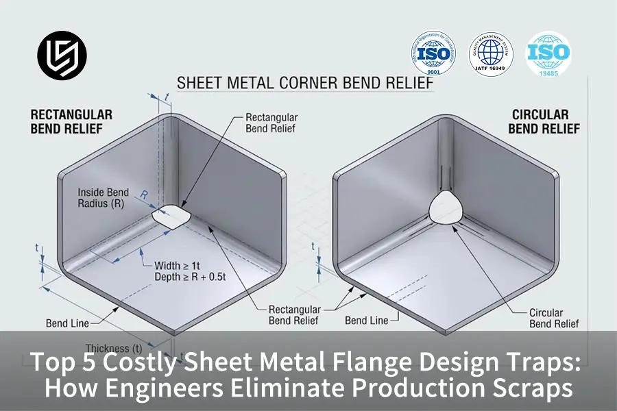
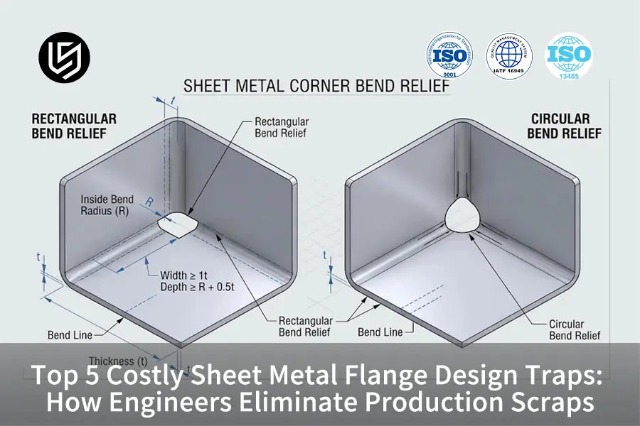
- Stress Relief: Relief holes in rectangle or circular configuration (depth > R + 0.5t) help to avoid tearing due to the perpendicular junctions of flanges and ensure flatness of the chassis.
- PEM Nuts/Alignments Holes Retention: Hole/Bend spacing of ≥ 2.5t + R prevents stretching of holes and provides rigid retention of PEM nuts/alignments holes.
- Economy of Standardization of the Tooling: Utilizing the same bend radius in the whole design reduces the number of setups on machines and lowers production costs by 22.5%.
Why Does Minimum Flange Length Trigger Press Brake Scraps?
The Minimum Flange Length is the final dimensional limitation that is very necessary for the sheet metal blank to move over the shoulders of the press brake V-die opening during the forming process. In case an engineer designs a flange length that is smaller than 4t + Bend Radius, then the edge of the sheet metal will not have physical contact with the shoulders of the die prior to the plastic deformation process. For the 8t die set-up, if the flange dimensions are less than the acceptable value, then there is premature sliding of the flange into the die resulting in angular mistakes from 3° to 7°, edge distortion and permanent punch indentation.
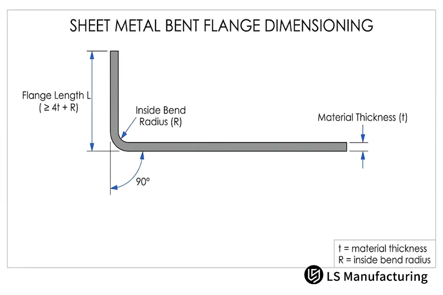
Figure 2: Standard engineering 2D CAD cross-section showing minimum flange length L (≥ 4t + R) dimensioned from the free edge to the outside bend tangent.
Below is the effect of flange length dimensions with respect to press brake tooling:
|
Flange Length Parameter |
Tooling Support Status |
Forming Risk Level |
Cost & Scrap Impact |
|
< 2.5t + R (Severe Undersize) |
Zero shoulder contact in 8t die |
Critical (Die slippage / tool crash) |
Immediate scrap (100% rework failure) |
|
2.5t to 3.5t + R (Borderline) |
Unstable friction contact |
High (Angular skew & edge burring) |
+20% machine cycle adjustment time |
|
≥ 4t + R (Standard Rule) |
Full bilateral shoulder support |
Zero risk (Stable air bending) |
Optimal unit cost & zero scrap baseline |
How Can Standard Bend Radius Prevent Outer Grain Cracking?
The inner radius determines how much tensile strain will be placed upon the outer layer grain structure of the sheet material. In selecting an extremely small inner radius, particularly a zero-radius sharp corner in work hardened or temper hardened materials like 6061-T6 aluminum or hard rolled stainless steel, this places extreme stress upon the outer grain structure beyond its inherent elongation capacity, resulting in extreme micro-fracturing and surface fracturing along the bend axis, causing fatigue failure under end-use dynamic loads. LS Manufacturing eliminates outer grain fracture by employing a proven three-step procedure for press brake set-up:
- Step 1: Calibration of Radius to Material Ductility: Set the inside bend radius as 1t or more for ductile materials (such as 5052-H32 aluminum and mild steel) and 2t or more for less ductile heat-treated materials (for example, 6061-T6 material).
- Step 2: Orientation of Bend Line Relative to the Rolling Grain of the Mill: Place any 90° bend line across the rolling grain of the sheet metal whenever nesting of sheet blanks permits, avoiding crack propagation.
- Step 3: Polishing of Contact Surface of Tools: Use precision-ground and hardened punches with a surface roughness of Ra 1.6μm that will distribute friction forces over the entire arc.
Engineers who adopt the same bend radii for all components save on replacement time for tools and thereby maintain good yield as well as intact structural integrity without surface cracks.
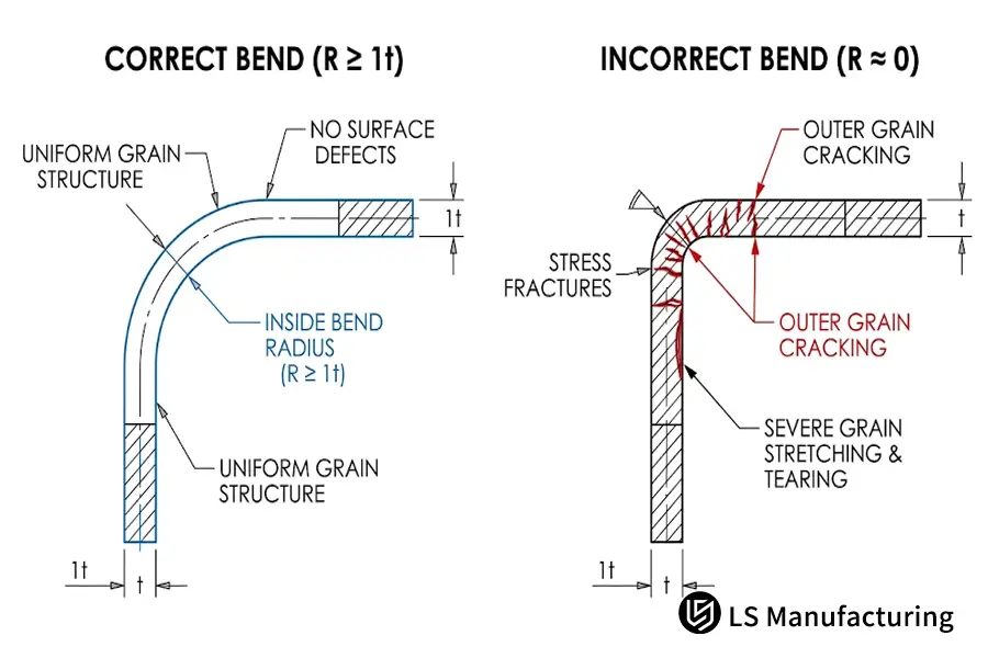
Figure 1: Micro-cracking mechanism in sharp zero-radius corners compared with uniform stress distribution using recommended inside bend radius (R ≥ 1t).
Why Is Sheet Metal Bend Relief Critical For Part Flatness?
Sheet metal bend relief refers to an engineered rectangle or tear-drop cutout which is created at the point where a bent flange meets with an adjacent straight side or other perpendicular flange. In a 90° forming process, the compressive and tensile force acts across the sheet and causes bulge of the material at the bend region. Without special relief slots, the increased volume of such a bulge tears apart the adjacent metal and distorts the adjacent mounting surface by 1.2mm. At LS Manufacturing, it is ensured that CAD stress relief slots isolate the deformation completely within the forming region.
Geometric Sizing Criteria for Effective Stress Relief Slots
For effective isolation of deformation regions, the geometric ratio of relief slots should be kept within certain limits. The width of the stress relief slot should be equal to or more than the thickness of sheet metal (1t) while the depth of the relief slot should exceed the tangent point from inside bend radius by at least half the thickness (R + 0.5t). Rectangular stress relief slots work most effectively on CNC turret punch presses and fiber lasers while circular/tear-drop reliefs reduce notch sensitivity of vibration prone aerospace brackets.
Consequences of Assembling Without Relief Cuts
The consequences of the removal of relief cuts as an economy to shorten CAD layout time is serious manufacturing disadvantages for assembling. The displacement of material at sharp corners produces uncontrolled puckering at flat flanges making gasketing impossible in IP65 enclosures. Besides, secondary manual deburring and grinding necessary for aligning the parts results in additional cost of $4.50 to $8.00 per piece along with damaging the anti-corrosive cladding layer.
What to Do to Prevent Hole Distortion Due to Sheet Metal Warping?
Hole distortion can be described as the ovalization and expansion of thread pitch due to the placement of holes, slots, or cutouts in the plastic deformation zone around the bend line. In the course of the bending process, the sheet metal area located 2.0 times thickness beyond the bend line tangency deforms heavily. This way, holes situated within this deformation area will become teardrops. Consequently, the installation of threaded fasteners, dowel pins, and PEM hardware will immediately become impossible. LS Manufacturing establishes strict geometric keep-outs on all customer drawings for 100% secure fastening.
Hole-to-bend keep-out distance recommendations depending on cutout geometry are presented in the table below:
|
Cutout Feature Type |
Minimum Keep-Out Distance |
Deformation Mechanism Prevented |
Secondary Process Alternative |
|
Standard Round Clearance Hole |
≥ 2.5t + Bend Radius |
Bore elongation & diameter ovalization |
CNC reaming after bending |
|
Threaded / PEM Clinch Hole |
≥ 3.0t + Bend Radius |
Thread pitch pitch-distortion & clinch pull-out |
Secondary press clinch tooling |
|
Long Rectangular / Wire Slot |
≥ 3.5t + Bend Radius |
Unsupported wall bulging & edge collapse |
Bridge-tied laser relief tabs |
|
Countersunk Screw Hole |
≥ 3.5t + Bend Radius |
Asymmetrical bevel distortion & loose heads |
Secondary CNC counterboring |
The Numbers Explained: Technical Insights in the Real World
LS Manufacturing runs a state-of-the-art 8,000 square meter digital manufacturing operation that is fully accredited for both ISO 9001:2015 and AS9100D aerospace quality systems standards. This technical guide is written by Gloria who is the Senior Manufacturing Solutions Architect and Rapid Prototyping & Rapid Manufacturing Expert and has more than 15 years of precision engineering experience. The technical insights provided herein were crafted in partnership with our experienced senior shop floor tooling engineers and are based on real world data from over 1,200 evaluated client CAD jobs annually.
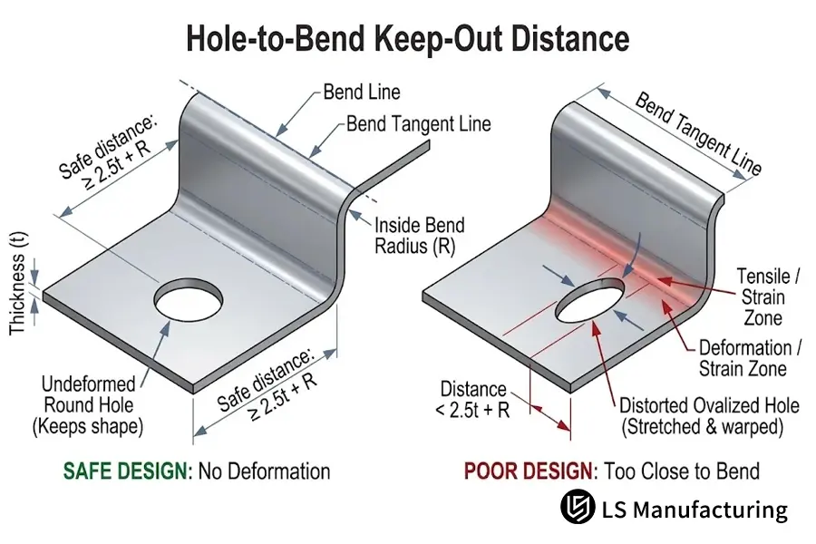
Figure 3: Plastic deformation zone boundary and required keep-out clearance (Distance ≥ 2.5t + R) preventing hole ovalization and PEM fastener retention failure.
Why Do Tapered Flanges Require Dedicated Support Tabs?
A tapered flange is a slanted sheet metal element wherein the outer shape gradually becomes narrow in relation to the direction of forming, in contrast to a flange that maintains a parallel edge. As a sheet metal blank is fed into the CNC press brake with a non-parallel profile, it is impossible to achieve constant two-points contact with the backgauge finger stopper since there is no flat edge for registration. This causes dynamic movement of the sheet metal during punch travel and results in significant angular distortion of parts produced. LS Manufacturing addresses the problem of backgauge instability by using the following two manufacturing processes:
- Process A: Minimum Flat Edge Requirement: Provide minimum non-tapered edge of 4t length at the end of the flange in order to allow for sufficient flat registration with press brake fingers.
- Process B: Temporary Aligning Tab Placement: Add disposable aligning tabs to the laser flat pattern nesting. The aligning tabs ensure square registration with backgauges and can be easily broken off along micro-joint lines after bending process is completed.
By implementing sacrificial registration tabs in CAD, engineering teams achieve tight ±0.01mm–±0.02mm contour repeatability across irregular chassis profiles without designing expensive specialized tooling fixtures.
Which Factors Determine Practical Sheet Metal Tooling Cost?
Sheet metal tooling cost involves the actual cost involved in purchasing specific punch-and-die sets, custom wiping tools, and machine downtime due to changing of tools. Specifying non-conformable inside radii or multiple bend radii on one sheet will mean that press brake operators will have to change machines in sequence, and this will lead to increased production costs. LS Manufacturing recommends that engineers standardize bend radii throughout all drawing elements in order to facilitate single setup operations, thereby lowering fabrication cost by 22.5%.
A matrix showing how the choice of flanges affects the economic cost of tooling in the shop floor is shown below:
|
Design Choice |
Tooling Impact |
Setup Downtime |
Per-Unit Cost Impact |
|
Unified Radii (All R = 1t) |
Standard press brake tooling |
Zero teardown overhead |
Baseline (Lowest overall cost) |
|
Mixed Radii (R = 1t & 3t on same part) |
Multi-stage segmented tooling |
+45 mins per batch setup |
+18% Cost increase |
|
Sharp Internal Corners (Zero Radius) |
Custom ground punch tools |
+2 weeks tool procurement |
+25% Cost increase |
|
Relief-Free Adjacent Flanges |
Manual post-form grinding |
Continuous scrap & repair |
+35% Cost increase |
How Does Strict DFM Ensure Consistent Production Quality?
Design For Manufacturability (DFM) is an engineering field which examines 3D CAD models based on physical manufacturing considerations before cutting any metals and creating tooling. Since it is possible to analyze press brake punch clearances, bend deductions and possible interference ahead of time, manufacturing engineers can find geometrical issues without any machine idle time required for making necessary changes. In LS Manufacturing, we use automated DFM checking systems that compare each uploaded file according to ISO 2768-f standard tolerances, eliminating all future scraps and speeding up delivery times.
K-Factor and Bend Allowance Digital Simulation
Unfolded flat pattern calculations fully depend on accurate CAD bend deduction and real material K-factors (a ratio of the neutral axis location to sheet thickness). Default values in the software usually differ from real tooling by 0.2mm to 0.5mm per bend. Due to the usage of empirical K-factors, obtained during calibration of our tools sets, we can guarantee perfectly closed seams and absence of corner overlaps in multi-flange enclosures.
Flange Clearance and Tool Collision Checking
Deep U-channel forms and return flanges may present the potential for physical tool collision between the punch holder/ram and secondary/tertiary bend cycle operation. Pre-production 3D kinematic forming simulation ensures sufficient clearance between all deep U-channel and acute profiles for both gooseneck and acute punches. Design checking that recognizes tool collisions permits slight changes to the flange profile to eliminate the requirement for costly offset tools.
When Do Engineers Need Custom Sheet Metal Services?
Custom sheet metal services are essential when design requirements necessitate process integration, tight geometric tolerances, and surface treatment standards that standard sheet metal job shops cannot achieve. Where electronic enclosures or medical consoles require integration of fiber laser cutting, air bending, CNC milling to tight tolerances for ±0.005mm bearing seats, ASME B1.1 threaded hardware installation, and MIL-A-8625 Type III hard anodize, single-discipline companies are creating substantial risks in terms of tolerance stack-up. LS Manufacturing provides complete contract manufacturing with total AS9100D compliance:
- Aerospace & Medical Enclosure Integrity: Chassis with required environmental sealing, EMI shielding, and vibration rigidity can be accommodated by our combined CNC mill and precision form capabilities.
- Complex Multi-Axis Secondary Machining: Parts that require sub-millimeter positioning tolerances on formed faces are machined using 5-axis CNC with high speed and precision using Zeiss CMM technology.
- Stringent Surface Treatment Requirements: Parts that require 50μm hard anodizing with 1,000 hour ASTM B117 salt spray corrosion resistance can achieve this within our certified in-house surface treatment facilities.
Using one ISO certified supplier to perform all of these operations will eliminate the logistical hold-up between suppliers while allowing you to keep track of your dimensioning.
Case Study: LS Manufacturing Custom Forming for Medical Endoscope Enclosure
Engineering Problem: A Tier-1 medical instruments manufacturer was facing major problems in manufacturing due to the pilot run of an aluminum endoscope control console. The first client CAD model required the use of 2.0mm 6061-T6 aluminum sheet metal with internal chassis flanges of length 5.0mm (far less than what could be considered safe for a v-die stretch). In addition to this, bend reliefs were absent on the corner junctions while alignment holes were spaced just 2.0mm from the 90° bend line. During pilot manufacturing runs with a regular outsourcing facility, a disastrous 18.4% scrap rate was achieved where undersized flanges fit into the die cavities and critical alignment holes became elongated to 0.35mm with stretched PEM nut retention.
DFM Analysis & Problem Solving: LS Manufacturing's engineering experts performed a thorough DFM analysis and re-engineering of the enclosure shape. Flange lengths were optimized to 9.0mm (as per the minimum ≥ 4t + R rule in relation to the 8t die opening). Stress relief holes of size 2.0mm x 3.0mm were added at all perpendicular junctions of flanges.To mitigate micro-cracking at grain boundaries in 6061-T6 aluminum, our team has applied intermediate localized induction stress relief anneal along with press brake dynamic pressure compensation curves calibration.
Quantifiable Production Results: The engineering modifications have resulted in a dramatic change in production process. The scrap rate has been reduced from 18.4% to 2.3%. The unit cost of production has been decreased from the original $80.00 to $62.00, thus, showing 22.5% production cost savings. Additionally, due to removal of multi-tool setups and rework, production lead time for the first 500 units has been decreased from 14 days to 9 days (35.7% schedule improvement). Tolerances for precision mounting holes ±0.005mm have been obtained through CNC finishing of bent surfaces.
Compliance & Verification: The manufactured enclosures have been subjected to quality assurance checks satisfying all AS9100D documentation requirements. Parts have undergone MIL-A-8625 Type III Class 1 hard anodize coating (50 μm thickness) and have successfully passed 1,000 hours neutral salt spray test ASTM B117 without pit corrosion. Parts dimensions have been verified using Zeiss CMM with MPEE of 0.0009mm.
Data Source & Baseline: LS Manufacturing Medical Device Sheet Metal Production Database, Project Log #MED-2026-084 (More than 1,200 sheet metal parts assessed).
FAQs
How does sheet thickness influence the minimum flange length calculations?
Minimum flange lengths vary directly with sheet thickness based on the formula L ≥ 4t + R, which ensures that the workpiece covers the standard 8t opening of the V-die without slipping into its cavity to provide guaranteed ±0.01mm air-bending accuracy for LS Manufacturing.
Why is the 6061-T6 aluminum prone to fracturing during the sheet metal bending process?
Based on its precipitated hardening nature and low room temperature elongation rate, 6061-T6 breaks when formed around sharp radii. LS Manufacturing reduces grain fracturing through the provision of inside radius ≥ 1.5t to 2t and local induction stress relief.
What is the typical tooling tolerance in precision sheet metal bending?
Based on the utilization of calibrated CNC press brakes, along with automatic laser angle tracking systems, LS Manufacturing is capable of keeping linear tolerances at ±0.01mm–±0.02mm and angular ones at ±0.5°.
Are distorted holes around the bend line repairable?
Holes distorting into an oval can never be corrected for cylindrical tolerance using cold rework. LS Manufacturing handles stringent tolerance hole requirements on the bend area through additional secondary precision CNC milling, at ±0.005mm center-to-center true position.
What effect does bending relief size have on structural rigidity?
Too small bending relief causes material tear, whereas too large bending relief results in structural rigidity and poor EMI shielding effectiveness. At LS Manufacturing, bending relief is kept 1t wide and R+0.5t deep to retain Ra 1.6μm baseplate flatness, optimizing torsional stiffness.
What is the effect on lead time when specifying common bend radii on a chassis?
Common bend radius specification enables complete part forming through a single press brake operation with no tool change. This practice reduces cycle time by 35.7% at LS Manufacturing, lowering 14-day production lead time to 9 days.
What is the impact of hard anodization on the dimensional tolerance of bent flanges?
MIL-A-8625 Type III hard anodization creates 50μm overall film thickness (25μm penetration and 25μm surface growth). LS Manufacturing incorporates this growth into the design of the CAD flat pattern to avoid interference during assembly after coating.
Why do LS Manufacturing request 3D CAD drawings for DFMA at an early stage?
3D STEP and IGES drawings enable automation of kinematic simulation of sheet metal unfolding, accurate K-factor calculation, and punch interference checking. LS Manufacturing provides comprehensive DFMA evaluation in 2 hours of receiving the file.
Conclusion
The best way to avoid unforeseen scrap costs and schedule delays is to follow basic principles of sheet metal flange design such as flange length clearances, proper inside radius, and stress relief notches. At LS Manufacturing, our ISO 9001:2015 and AS9100D aerospace certifications combined with our CNC press brakes and 5-axis secondary machining services allow us to take on the most challenging sheet metal designs and deliver perfect production parts.
Engineering Action Step: Are tight hole tolerances or flange cracking jeopardizing your production start? Upload your 2D and 3D CAD designs (STEP, IGES, or DXF) at the LS Manufacturing quote portal right now. Our engineering team will provide you with a detailed DFM analysis and quotation in just 2 hours!