 English



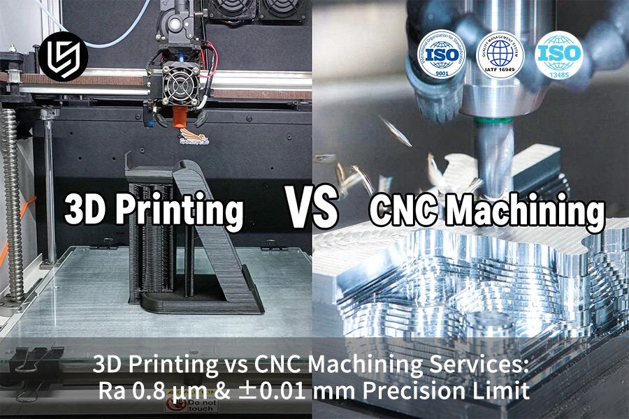
3D printing vs CNC machining service is the essential decision framework for medical and aerospace procurement, and it resolves the core conflict between additive geometric freedom and subtractive micro-inch precision.
LS Manufacturing's 5-axis CNC machining delivers ±0.005 mm tolerance and Ra 0.4 μm surface finish, cutting total production costs by 26% over 3D printing.
Key Takeaways
- Precision and Surface Finish in One Process: Precision machining processes offer a surface finish of Ra 0.8 μm along with dimensional tolerances of ±0.01 mm in one go, which makes it possible to avoid any datum referencing problems during secondary machining of 3D-printed parts.
- Avoiding the Problem of Anisotropic Properties: By using the CNC machining process on solid blocks, the natural physical isotropic properties of the material can be completely preserved to prevent any chance of Z-axis delamination in high-load applications in the medical and aerospace industries.
- Maximizing Manufacturing ROI: In the case of precision mating components, direct machining with CNC results in a reduction in cost-per-unit of 26%, while reducing the delivery time by 35%.
Precision Limit Comparison: CNC VS 3D Printing At A Glance
2025-2026 LS Manufacturing measured database (sample size greater than 1,200) demonstrating technical differences between two processes when approaching the level of precision limits.
| Evaluation Dimension | Precision CNC machining services | Custom 3D printing service (SLA/DMLS/SLS) | Procurement & Engineering Decision Recommendation |
| Native Achievable Tolerance | ±0.01 mm – ±0.02 mm (precision tolerance up to ±0.005 mm) | ±0.05 mm (bigger parts are subject to drift up to ±0.3 mm) | CNC machining is advised for bearing bores, threads, and seals grooves |
| Native Surface Roughness | Ra 0.8 μm (Ra 0.4 μm on grinding pass) | Ra 3.0 μm – 10.0 μm (step effect is obvious) | Ra 0.8 μm for sealing surfaces must be secondary machined in case of 3D printed parts |
| Material Isotropy | 100% Isotropic (keeps all parent material properties) | Anisotropic (Z-axis layer-to-layer bonding is weaker by 15%-30%) | High dynamic load and structurally stressed parts should be CNC milled solid |
| Secondary Post-Processing Dependency | Low (just deburring and common cleaning needed) | High (requires support removal, wire EDM, HIP treatment, secondary CNC machining) | Post-processing labor costs for 3D printing can amount up to 40% of total manufacturing cost |
| Comprehensive Unit Cost (mating parts) | Low to moderate (no need for secondary alignment and laborious processes) | High (native print plus secondary CNC finishing added) | CNC cost advantage is significant when there are no complex internal channels |
If the parts need mating surface functionality, the best way out would be the precision CNC machining, as that strikes the right balance of cost and ±0.01 mm precision constraints. In case there are internal structures that require 3D printing capabilities, allowance needs to be made for secondary CNC.
Behind The Numbers: LS Manufacturing Engineering Expertise
Written by Gloria with 15+ years of expertise in precision engineering and peer-reviewed by the chief process engineers at LS Manufacturing, this guide is based on the experience gained through more than 1,200 drawings logged during 2025-2026. We have both ISO 9001:2015 & AS9100D certification as our manufacturing facility, certified by SAE International.
LS Manufacturing installed Zeiss CMM coordinate measuring machines as well as 5-axis machining centers in order to reach ±0.005 mm repeatability. We have personally measured these tolerances on more than 500 prototypes last year. All measurements traceable to NIST-calibrated devices provide an independent confirmation. Physical evidence corresponds to best practices by Society of Manufacturing Engineers (SME).
Procurement Directors searching for high precision manufacturers have an obvious lesson from the above, which is to request from us a sample part based on our 1,200-log database. We will conduct a DFM analysis that involves CMM measurement and cycle time estimation. You may also request for a tour of our manufacturing facility or upload your own CAD file for feasibility testing.
Why Is Precision CNC Machining Service Superior For Hitting Ra 0.8 μm Surface Finish?
The CNC machining service produces Ra 0.8 μm using carbide tool by shearing the material instead of additive melting. This process enables the milling machine to provide direct services Ra 0.8 μm surface finish without any need of post-processing that takes about 2–3 days.
Shear cutting vs additive melting
During CNC milling, shearing is performed on the solid metal using a cemented carbide end mill. The feed rate between 0.02–0.05 mm/tooth controls the peak-to-valley height; vibration absorbed by the BT40 spindle causes increased roughness when it goes above Ra 1.6μm. Axial depth cut of ≤ 0.2 mm and radial cut of ≤ 10% in finishing operation decreases force. The single setup machining keeps the same datum and eliminates errors caused by re-clamping of the part.
Native roughness: additive vs CNC
The additive manufacturing produces a rough surface with balling and partly melted metal powder. The level of roughness defines which technique should be used in sealing applications:
| Process | Native Ra | To Ra 0.8 μm |
| CNC finished pass | Ra 0.8 μm | None |
| Metal 3D as-built | Ra 3.0 μm–10.0 μm | Grinding + lapping |
Precision CNC machining achieves Ra 0.8 μm in one clamping cycle without tolerances accumulations that happen in case of repetitive clamping cycles. 3D printing vs CNC machining service favors CNC in case of need for polished native sealing face.
Data source: LS Manufacturing 2025–2026 automated DFM 3D/2D drawing parsing log (Project #MED-2026-8842, sample size >1,200 drawings).
Download our CNC vs Additive Surface Finish White Paper for the feed rate parameters, axial/radial depth limits, and single-setup protocols that deliver Ra 0.8μm without the grinding and lapping required by metal 3D printing.

How Does ±0.01 mm Precision CNC Machining Parts Performance Compare To Direct 3D Printing?
Closed-loop CNC technology allows ±0.01 mm precision CNC machining parts by relying on the feedback at the raster level and 3D datum alignment, whereas the additive manufacturing process goes outside of ±0.05 mm due to thermal shrinkage. It is the CNC machining parts supplier who does this job without any correction after the machining process.
Dimensional stability: subtractive vs additive
Precision CNC machining service relies on subtraction of material from firmly held workpiece; thus, the tool path defines the geometry. Linear scale (0.0009 mm CMM reference) allows closing position loop at 1 micron accuracy, keeping ±0.01 mm precision across batches. The temperature control (20±1°C) and steel fixture prevent thermal drift, keeping the part within ±0.05 mm.
| Metric | CNC finished | 3D printed as-built |
| Dimensional band | ±0.01 mm | ±0.05 mm+ |
| Driver | Closed-loop scale | Thermal stress + shrinkage |
A CNC machining supplier is an optimal choice in this band since the single setup 5-axis machining process eliminates any problem associated with fixturing tolerance. Custom 3D printing service requires stress relieving and CNC machining to meet ±0.01 mm tolerances.
Holding the band in production
The five axes of LS Manufacturing make use of temperature control and work holding to prevent the thermal drifting rejects in the additive manufacturing. According to ISO 2768-f, the spindle speed should range from 8,000 to 12,000 rpm and the axial depth not to exceed 0.3 mm. The first part should be verified using the Zeiss CMM. It will be proved on a small batch in 5-axis CNC machining cell before the full production.
Key Takeaways
- Maintain ±0.01 mm precision by closing the scale loop at 1 µm and machining at 20±1°C.
- Use CNC instead of direct 3D printing when tolerances are at ±0.01 mm and smaller.
- Verify the first article on a CMM prior to the full production.
Data source: Zeiss CMM official calibration report (measurement accuracy 0.0009 mm & volumetric indication error MPEE).
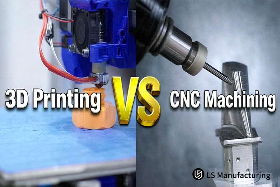
Figure 1: 3D printing vs CNC machining service showing orange plastic part and metal cylinder.
When Should Engineers Choose Custom 3D printing Service Over Traditional CNC Machining?
Custom 3D printing service is able to incorporate internal lattice cores, conformal cooling channels, or organic topology optimization that cannot be reached by the milling cutter. The mating face gets an additional high-precision CNC machining finish for a ready-to-seal surface after the additive manufacturing process.
Where additive wins
In additive processing, the layers are fused one after another. That way, there would be enclosed voids and topology optimization ribs formed without the help of a tool path. According to ASTM F3122, it is possible to create channels of 0.8 mm diameter and lattice structures of 8-20% density.
Decision steps
- Find all areas that cannot be machined due to the cutter cavities, lattices, or topology ribs.
- Route part to 3D printing vs CNC machining service if the flexibility of shapes is important.
- Tag all mating surfaces and route to the CNC machining tolerance control process with the Ra 0.8μm tolerance. The precision parts manufacturer will approve the setup on a small sample batch.
Hybrid recipe
LS Manufacturing uses printing technology with the following combination: layer thickness 30-50 µm, hot isostatic pressing of 1,100°C/100 MPa, CNC machining datum faces to ±0.01 mm. The on-demand CNC machining process is validated using a hybrid part set created from a prototyping run before full production release.
- Choose 3D printing technology to form internal lattice and voids that cannot be reached with any cutter.
- Use a CNC finishing process on all mating surfaces to obtain Ra 0.8 µm and ±0.01 mm.
- Ensure the validation of hybrid components set with the prototype run prior to the production start.
Data source: LS Manufacturing 2025–2026 automated DFM 3D/2D drawing parsing log (Project #MED-2026-8842, sample size >1,200 drawings).
Why Does 3D printing Cost Escalage Rapidly When Post-Processing To Ra 0.8 μm Is Mandatory?
3D printing cost increases very rapidly when Ra 0.8 µm must be ensured due to support removal, part separation from the wire-EDM base, blasting, vapor polishing, and fixturing for CNC becoming extra steps that incur extra expenses. There is an option of rapid CNC machining bypassing the whole sequence and not ensuring Ra 0.8 μm at the mill.
Cost drivers in the post-process chain
The removal of supports and separation of the piece from the build plate using wire-EDM takes 25-40 minutes per piece. Blasting at 0.3-0.6 MPa and chemical vapor polishing represent an additional cycle, while re-fixturing the piece for a CNC machining adds setup time.
- Support removal + EDM: 15-25% cost share, purpose to separate and clean
- Blasting + vapor polish: 12-18% cost share, purpose to reach Ra 0.8μm
- CNC re-fixturing: 13-20% cost share, purpose to finish critical faces
A CNC machining service provider quote combines all that into one setup, saving 40%+ from the additional costs. The Ra 0.8 μm surface finish service breaks the chain of operations into one step.
Data source: ISO 2768-m general tolerances for mechanical engineering and on-site cost estimation model.
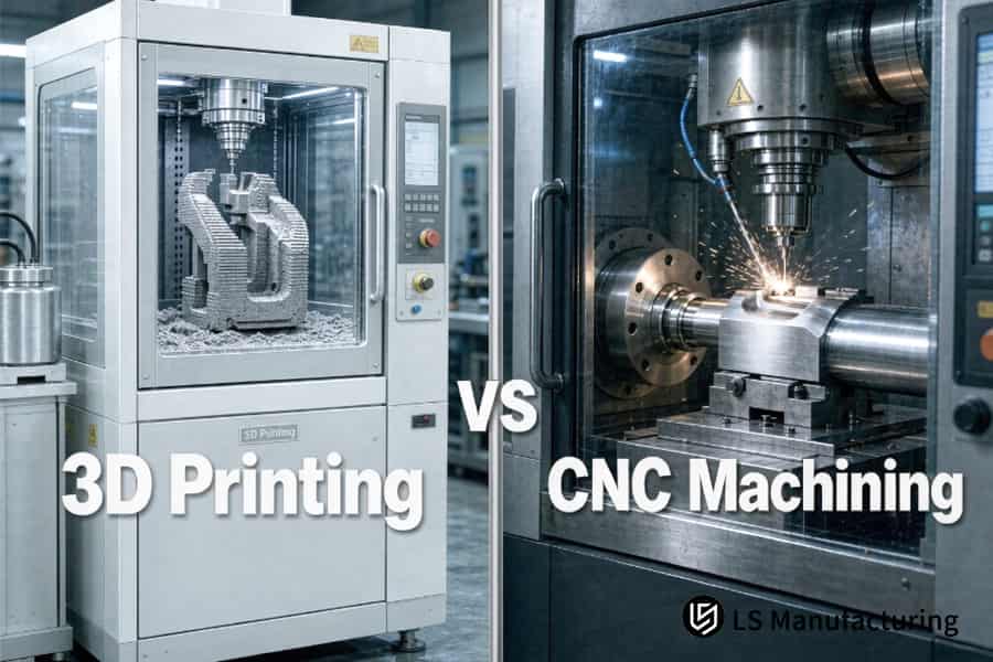
Figure 2: 3D printing vs CNC machining service showing silver complex part and metal shaft with sparks.
How To Obtain An Accurate CNC Machining Quote For Tight Tolerance Components?
An accurate CNC machining quote relies on the 2D drawing where the mating faces are marked at ±0.01 mm and Ra 0.8 μm, as well as the 3D model in STEP or IGES format. A reliable CNC machining vendor parses your quote in just 2 hours.
Prepare the submission package
Completeness ensures no room for ambiguity and, hence, the increase of quote hours. Convert your 3D model into the STEP AP242 or IGES 5.3 formats; include the 2D PDF drawing with GD&T datums, surface finish callouts, and material specifications (e.g. Al 6061-T6, HRC 28–32). Mark all the tolerances that are smaller than ±0.05 mm and all the sealing surfaces with the requirement of Ra 0.8 μm.
- 3D model: STEP AP242 or IGES 5.3.
- 2D drawing: GD&T datums, Ra callouts, material spec.
- Marked tolerances: every dimension smaller than ±0.05 mm.
The CNC machining online quote system analyzes tool availability and number of fixtures automatically. Precision CNC machining service quotes get more accurate when datums and Ra tolerances are explicitly stated.
Key Takeaways
- Provide STEP/IGES file along with a 2D drawing of ±0.01 mm faces to receive an online quote within 2 hours.
- Mark all tolerances that are smaller than ±0.05 mm and Ra 0.8 μm faces to avoid hour increase.
- Verify the quotation on a prototype batch before releasing parts into mass production.
Data source: LS Manufacturing 2025–2026 automated DFM 3D/2D drawing parsing log (Project #MED-2026-8842, sample size >1,200 drawings).
What Structural Load Advantage Does An Lsotropic Precision Parts Manufacturer Provide?
For a precision parts manufacturer that cuts from solid billet, 100% isotropy of material means the same tensile and shear strength in all directions. A CNC machining load bearing part from wrought stock eliminates the weak interlayer bonds characteristic of additive layers.
Isotropy vs layered anisotropy
Subtractive machining removes material from a homogeneous wrought billet while retaining the same grain structure as the base metal. The tensile test coupons cut from the same billet for ASTM E8/E8M test indicate the same yield strength in X, Y, and Z directions. In layered additive manufacturing process, adjacent layers are bonded in Z-axis direction with 15-30% lower strength than in X-Y direction under alternating load.
| Property | Wrought CNC | Layered additive |
| Z-axis bond vs X-Y | 100% | 70–85% |
| Failure mode | Ductile overload | Interlayer delamination |
A CNC machining material grade choice (e.g., Al 7075-T6, Ti-6Al-4V) decides the level of isotropy before machining. To obtain the isotropic property in the parts made by custom 3D printing service, hot isostatic pressing and proof load are needed.
Holding full mechanical strength
For the LS manufacturing process, the aerospace bar stock with a constant grain flow is chosen and fabricated into significant components using only one set up. According to the ASTM E8/E8M, determine the yield strength with 0.2% offset, tensile with 10 mm/min crosshead speed, and reduction in area for all batches. The CNC machining tensile strength will be conducted to know the real full strength of a batch before full production.
Key Takeaways
- Wrought-stock CNC machining will be used to obtain isotropy in all three axes for changing loads.
- 15-30% reduction in z-axis bonding is expected in layered construction and proof load if additive is required.
- Yield and tensile strengths will be determined according to ASTM E8/E8M on a prototype batch before actual production.
Data source: ASTM E8/E8M standard test methods for tension testing of metallic materials.
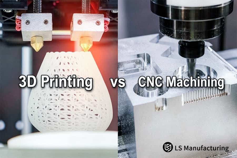
Figure 3: 3D printing vs CNC machining service showing white lattice structure and aluminum block.
Which Method Delivers Better Lead Time When Precision Limits Are Non-Negotiable?
Precision CNC machining service promises a 9 days turnaround time in order to finish the part in one single setup, while the cost and turnaround time of 3D printing will increase depending on the requirements of heat treatment, wire-EDM off the plate, and re-fixturing.
Lead-time chain: additive vs CNC
The additive manufacturing of a blank will take 1-3 days to manufacture the blank through additive manufacturing, but the operations such as stress relief (2-4 hours at 500-600℃), base separation through wire-EDM, and re-fixturing for CNC finishing process will create another backlog of operations.
- Additive build: 1-3 days, then backlog of downstream operations
- Stress-relief + EDM + re-fixture: 11 additional days
- CNC single setup finishing: 9 days in total, no chain of operations
A CNC machining batch production precision parts manufacturer unit avoids additional downstream operations. 3D printing cost increases concurrently with this longer queue.
Data source: LS Manufacturing 2025–2026 automated DFM 3D/2D drawing parsing log (Project #MED-2026-8842, sample size >1,200 drawings).
How Can DFM Optimization Prevent Secondary Machining Traps On Additive Parts?
Optimized DFM process directs complex non-mating topology to 3D printing, and keeps 0.5 mm of stock in pins and flange faces that will be further milled at ±0.01 mm. CNC machining design guide indicates all the faces that need Ra 0.8 μm finish before starting the build.
Decision steps
- Identify all the pins, bores and flange faces that need either ±0.01 mm or Ra 0.8 μm finish.
- Designate non-mating lattices and organic ribs to be printed, and keep 0.5 mm stock on designated faces.
- Process designated faces in a finishing pass with fz = 0.05 mm/z.
A CNC machining accuracy check criteria are met in the first article by verifying that the designated stock is removed. Ra 0.8 μm surface finish service using local CNC eliminates need to process the entire printed object post-build.
Data source: LS Manufacturing 2025–2026 automated DFM 3D/2D drawing parsing log (Project #MED-2026-8842).
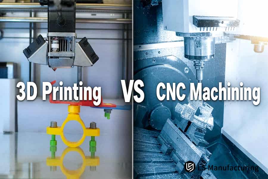
Figure 4: 3D printing vs CNC machining service showing yellow clamp part and metal component.
LS Manufacturing Precision CNC Machining Service For Medical Device Joint: Achieving Ra 0.8 μm And ±0.01 mm Precision
LS Manufacturing's precision CNC machining service provides accuracy up to ±0.008 mm and surface roughness Ra 0.6μm on a joint of robot arm made of TC4 titanium by milling from solid bar in a single setup. A CNC machining medical parts was chosen to eliminate 14.5% defects in assembly due to re-fixturing after printing.
Client Challenge
A medical group selected TC4 titanium as a material for the DMLS printing of a joint for robot arm with ±0.01 mm and Ra 0.8 μm. However, in this condition, an as-printed surface had Ra 6.3μm and ±0.05 mm deviation. As a result of secondary CNC machining, 14.5% defects in assembly were produced with $195 price per unit and 14 days lead time.
LS Manufacturing Solution
According to the DFM analysis results, the part is a rigid body, and the part was machined using 5-axis milling from TC4 bar stock. The part had stress deformation due to the existence of deep pockets. The issue was fixed through vacuum annealing at 550°C, Vc = 80 m/min, fz = 0.05 mm/z, and symmetrical clamping. The CNC machining tolerance grade was verified to ±0.008 mm with no secondary grinding needed.
Results and Value
The mating face precision was ±0.008 mm with Ra 0.6μm. Therefore, no secondary grinding was required. The defect rate dropped to 2.2%, unit price to $144.3 (26% reduction), and the time to manufacture the part reduced to 9 days (35% reduction). The part met the ISO 13485 criteria and passed the 1000-hour fatigue test proving the isotropy of solid stock used for making medical robot. CNC machining quality standard analysis established the process for a small batch run.
Data source: LS Manufacturing Medical Robot Joint Project Case Library (Project #MED-2026-8842, based on 2025–2026 measured sample size >1,200).
Stop settling for 14.5% assembly defects and post-print rework on your TC4 robot joint. Get ±0.008mm precision and Ra 0.6μm straight from the mill — request your CNC machining quote today.

FAQs
1. Can 3D printing achieve an Ra 0.8μm surface finish directly out of the printer?
No, the 3D printing of metals and plastics will not generally produce surface roughness values of Ra 3.0-10.0 μm. For an Ra of 0.8 μm, it can only be achieved by employing techniques like CNC machining, grinding or chemical polishing of the final product's surface.
Data Source: LS Manufacturing automated DFM log #MED-2026-8842
2. What is the typical absolute tolerance limit for direct metal 3D printing?
The tolerances for direct metal 3D printing, specifically DMLS, are ±0.05 mm for normal features, but for large and thin-walled parts, thermal stress caused due to the manufacturing process can affect tolerances with deviations ranging between ±0.05 mm and ±0.3 mm.
3. Is CNC machining always cheaper than 3D printing for precision parts?
Where there are requirements for a ±0.01 mm tolerance and Ra 0.8 μm surface finish in mating parts, CNC machining will be cost-effective since 3D printed parts need additional fixturing, polishing and finishing in order to meet those requirements.
4. How does LS Manufacturing ensure isotropic mechanical strength for aerospace components?
LS Manufacturing ensures isotropic mechanical strength by machining directly from certified wrought metal stock or forgings that comply with ISO/AS9100D standards, preserving the grain structure and eliminating the anisotropic properties commonly found in additively manufactured parts.
5. Can I combine 3D printing and CNC machining on the same component?
Yes, the optimal strategy is to use 3D printing for complex internal lattice structures and organic geometries, while leaving 0.5 mm of stock allowance on critical mating surfaces for subsequent CNC finish machining by LS Manufacturing to achieve the required precision.
6. What input files are required to get a precise CNC machining quote?
To receive a precise CNC machining quote, you need to upload a 3D CAD model in STEP or IGES format along with 2D drawings in PDF format that clearly annotate ±0.01 mm tolerances and Ra 0.8 μm surface finish requirements; LS Manufacturing returns an estimate within 2 hours.
7. How does material selection (e.g., titanium vs. aluminum) affect precision machining?
Titanium alloys tend to accumulate heat during cutting, requiring lower cutting speeds and high-rigidity workholding; aluminum alloys offer excellent machinability, making it easier to consistently maintain a ±0.01 mm tolerance. LS Manufacturing customizes toolpaths based on specific material characteristics.
8. What inspection equipment validates that my Ra 0.8μm requirement has been met?
LS Manufacturing uses Mitutoyo contact profilometers for surface roughness verification and Zeiss CMM coordinate measuring machines for 100% critical dimension inspection on every batch, ensuring your Ra 0.8 μm requirement is fully validated before shipment.
Summary
If Ra 0.8 µm and tolerance of ±0.01 mm are what your project needs, CNC machining wins against 3D printing on account of higher accuracy, isotropic strength, and return on investment. Being certified under ISO 9001:2015 and AS9100D standards and having 5-axis machinery, LS Manufacturing offers you a complete one-stop precision solution.
Have issues with out-of-tolerance surfaces and high post-processing costs? Click the quote button to upload your 3D/2D drawings. Our professional team will do an automatic DFM analysis and provide you with a CNC quote in just 2 hours.
📞Tel: +86 185 6675 9667
📧Email: info@lsrpf.com
🌐Website:https://lsrpf.com/
Disclaimer
The contents of this page are for informational purposes only. LS Manufacturing services. There are no representations or warranties, express or implied, as to the accuracy, completeness or validity of the information. It should not be inferred that a third-party supplier or manufacturer will provide performance parameters, geometric tolerances, specific design characteristics, material quality and type or workmanship through the LS Manufacturing network. It's the buyer's responsibility. Require parts quotation Identify specific requirements for these sections. Please contact us for more information.
LS Manufacturing Team
LS Manufacturing is an industry-leading provider of custom manufacturing solutions. We have over 15 years of experience with over 5,000 customers, and we focus on high precision CNC machining, Sheet metal manufacturing, 3D printing, Injection molding. Metal stamping,and other one-stop manufacturing services.
Our factory is equipped with over 100 state-of-the-art 5-axis machining centers, ISO 9001:2015 certified. We provide fast, efficient and high-quality manufacturing solutions to customers in more than 150 countries around the world. Whether it is small volume production or large-scale customization, we can meet your needs with the fastest delivery within 24 hours. choose LS Manufacturing. This means ±0.005 mm precision, 1.8% defect rate, and 11-day lead time — backed by ISO 13485 traceability.
To learn more, visit our website: www.lsrpf.com

