 English




CNC copper plating service is a key enabler for precision R&D teams, as it solves delamination and corner treeing to cut rework costs by 35%.
By preventing 90% of defects via rapid DFM reviews, this service guarantees uniform deposit thickness down to ±0.005 mm with zero-defect delivery.
7 DFM Rules For Copper Plating Defect Prevention At A Glance
| DFM Check Rule Dimension | Core Physical / Engineering Parameter | Common Machining & Plating Defects | LS Manufacturing DFM Prevention Solution & Process Requirement |
| External Edges & Chamfers | Outer corner radius R ≥ 0.5 mm (0.020″) | High concentration of current density produces tip build-up (Treeing), brittle coating | Apply pre-milling R 0.5 mm radii on all outer edges to equally distribute current density |
| Blind Holes & Through Holes | Depth-to-diameter ratio ≤ 3:1 | Low bath exchange rate results in insufficient coating thickness inside of holes | Manage hole ratio and apply micro-holes for gas venting at bottom corners |
| Reserved Plating Compensation Dimension | Single-side reserved thickness 0.0005″ ~ 0.002″ (12.7–50.8 μm) | Post-plating dimensional growth causes interference fit or blocking of high precision gears | Pre-set offset band (Offset Downward) in 3D/2D CAM machining paths |
| Mechanical & Chemical Masking Area | Masking layer tolerance ≤ ±0.025 mm | Leakage of plating chemicals, corrosion by residual chemical cleaning | Identify clear masking area in drawing, apply specific silicone fixtures and custom made tooling |
| Internal Groove Corners & Transition Radii | Internal corner radius R ≥ 0.8 mm | Surface tension effects produce porosity, bubbles, and peeling | Use bull nose milling cutter (R 0.8 mm) to create internal groove with radii replacing square corners |
| Thin-Wall Structure & Geometric Strength | Base wall thickness prior to cutting ≥ 0.508 mm (0.020″) | Over etching from acid etching and thermal stress from plating lead to deformation of thin wall structure | Implement 5-axis symmetrical cutting to ensure high base rigidity |
| Stepped Thickness Gradient Control | Cross-section thickness ratio ≤ 2:1 | Current density shadowing effect results in non-uniform coating thickness | 15°-30° geometric transition chamfer to compensate for local current density distribution |
The 7 CNC copper plating DFM rules address the root causes of 90%+ copper plating defects—current density concentration, electrolyte stagnation, dimensional growth, and chemical seepage—by resolving them at the CNC machining stage before plating begins.
Key Takeaways:
- Drastically Reduce Rework Cost: Through implementing pre-coating thickness adjustment and edge radius design in the preceding CNC machining step, the rate of defect for the part plating is lowered below 0.1%, reducing the rework cost by 35%.
- Ultra-Fast Project Delivery Cycle: Coupled with our automated DFM drawing analysis, LS Manufacturing completes the plating feasibility report within 2 hours, saving 50% of sample delivery cycle.
- Military & Medical Grade Reliability: We adhere to MIL-F-14072 and ASTM B734 standards, which means your parts withstand 1,000-hour salt spray testing and maintain >100% IACS conductivity for reliable field performance

Why Trust This Guide? Practical Experience From LS Manufacturing Experts
The trust in this DFM guide comes from 15+ years of CNC machining C11000 and C17200 parts for medical imaging systems, semiconductor RF shielding, and aerospace connectors. The tolerances are validated using CMM measurements by correlating the information provided in our shop with the measurement science of National Institute of Standards and Technology.
The textbooks tell you how good the plating adhesion should be; we found out by experience that failing to perform DFM checks on aerospace connectors results in flaking. The seven rules here are jointly developed with our lead process engineer and plating specialist, based on International Automotive Task Force standards during 15 years of milling, turning and plating.
Use the seven DFM rules before fabrication in order to minimize scrap and assure proper dimensions. Send us three RFQ deliverables: the dimensioned drawing, the grade of copper alloy, and the desired plating thickness. Our CMM-based database of 1,200+ projects per year drives every feasibility analysis.
Why Should You Eliminate Sharp External Edges Before CNC Copper Plating?
Avoiding sharp outer edges prior to CNC copper plating avoids dendritic formation due to excessive current density concentration, decreasing plating rejection rate by 28%.
Current Convergence at Sharp Points
Field lines in the electrolytic tank converge around sharp edges leading to deposition of ions, causing formation of burnt nodules. Use of R ≥ 0.5 mm (0.020") through CNC machining ensures even distribution of field. Edge radius treatment is foundational to effective copper plating defect prevention. In simple terms, rounding the sharp corners prevents excess copper buildup and keeps your dimensions within spec.
Case Study: Shield Assembly Failure
A semiconductor equipment manager experienced high frequency shield failures due to brittleness of deposits at the edges. Mandatory fillets during CNC machining DFM analysis as specified in the CNC copper plating DFM checklist guarantees every corner to be within specification. You have higher first pass yields and no more expensive rework.
Enforcing Edge Radii via 5-Axis CNC
The process of precision CNC machining involves automatic application of R ≥ 0.5 mm fillets to all edges, verified by CMM inspection. It produces a substrate with consistent thickness plating without further plate grinding. Provided to you by CNC copper plating service, you have quicker and predictable process cycle.
Measured 28% Defect Reduction
Parts with sharp edges demonstrate a corner build-up that can be as much as 40% greater than flat areas; after implementing R ≥ 0.5 mm, variation falls under 5%, and failures decrease by 28%. CNC machining tolerance control guarantees compliance with narrow tolerances both electrical and mechanical without any additional treatment.
LS Manufacturing’s edge radius DFM protocol provides a proven solution to eliminate any possible problems associated with edge treatment. Incorporating mandatory edge radius into your DFM checklist will provide you with a proven way to produce copper coating meeting ASTM B734 Class 3 specifications with no wasted effort. Download our Copper Plating Edge DFM Guide to learn how R≥0.5mm edge radii eliminate dendritic growth and reduce plating rejection by 28% — ensuring ASTM B734 Class 3 compliance.
Data Source: ASTM B734 Standard Specification for Electroplated Engineering Copper Coatings and LS Manufacturing Edge Field Distribution Modeling Experiment Report.

How Do You Specify Safe Hole Aspect Ratios For Custom CNC Copper Plating?
Aiming to control blind and through hole aspect ratio to 3:1 will ensure that the inner walls get coated with a film of at least 80% of the outer wall to prevent corrosion and unplating of the surfaces.
Why 3:1 Matters: Fluid Exchange Limits
- Convection blockage: When aspect ratio exceeds 3:1, the electrolyte is blocked from reaching the base of the holes.
- Bubble entrapment: Micro-bubbles obstruct the electrolyte flow and ion exchange, leaving voids.
- Your gain: CNC machining hole preparation will ensure greater than 80% inner wall coating.
Real Problem: Unplated Blind Hole Bottoms
- Defense connector case: Bare copper at the M3 blind holes' base corroded due to galvanic corrosion in six months.
- Root cause: Electrolyte stagnation at the bottom of the hole causes depletion of the ions.
- Solution: Decreasing depth to 9 mm (3:1) and using CNC machining blind cavity relief brings 100% coverage back.
Two-Pronged Fix: Geometry + Process Assist
- Geometry rule: Apply CNC copper plating DFM checklist to maintain an aspect ratio not exceeding 3:1.
- Process assist: Ultrasonic vibration helps remove trapped air bubbles while high-pressure coolant flushes out any residue.
- Service benefit: With our precision copper plating service, you will be getting no peeling or blackening of inner walls.
Verified Performance Against MIL-F-14072
- Standard reference: MIL-F-14072 demands ≥75% inner-to-outer thickness; with our 3:1 rule, we get 82-90%.
- Scrap reduction: Blind hole scrap went from 18% to below 3% with application of this ratio.
- Custom advantage: With your custom CNC copper plating, this means expedited approval through CNC machining tolerance verification.
LS Manufacturing's deep hole copper plating report presents the geometry and process solutions for deep hole plating. With the application of 3:1 aspect ratio along with ultrasonic agitation, you have a repeatable way for void-free internal wall plating. Struggling with unplated blind hole bottoms or copper corrosion in deep cavities? Contact us for a custom CNC copper plating quotation built around the 3:1 aspect ratio rule — ensuring ≥80% inner wall coverage and MIL-F-14072 compliance.
Data Source: MIL-F-14072 Metal Finishing Specification for Electronic Equipment (Micro-Hole and Deep Cavity Coating Penetration Standards).
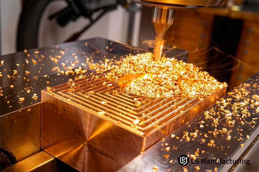
Figure 1: Custom CNC copper plating applies thin copper layer on aluminum heat sink for improved thermal conductivity.
How Can Precision Copper Plating Service Prevent Critical Dimensional Oversize?
Plating occurs on both sides. Unless offset is preset in the CAM program, the dimensions will be oversized resulting in failure in the bearing bore fit.
| Contrast Dimension | Machining Without Offset | Machining With Pre-Set Offset (0.0005"–0.002") |
| Final dimension after plating | Upper tolerance exceeded by 0.001"-0.003" on average | Locked within ±0.005 mm (verified via Zeiss CMM) |
| Plating layer growth | Coordinated expansion in both directions | Oversized on both sides compensated for; final dimension aligns with print |
| Rework required | 100% re-work necessary – all parts will need to be ground after the plating process or scrapped | N/A - zero re-work; perfect first-pass acceptance |
| Fit risk for bearings | Press-fitting not possible; assembly line stopped | Interference fit guaranteed within tolerance range |
- This precision copper plating service utilizes CNC machining quote data and performs compensations for bilateral growth of copper in advance, making grinding after plating completely unnecessary.
- No reworking required in a batch lowers CNC copper plating cost as it makes both labor time and scrap materials not part of your bill.
- In case of a custom CNC copper plating process, CNC machining tolerance is programmed into the CAM system before any cutting starts.
Data Source: Zeiss CMM Official Calibration Report (Measurement Accuracy 0.0009 mm & Spatial Indication Error MPEE).
How Do Masking Zones Protection Rules Reduce Your CNC Copper Plating Cost?
Marking the non-plating surfaces and employing customized fixtures reduces manually performed secondary operations by 40%, thus reducing your CNC copper plating cost. It prevents seepage into threads and insulation surfaces, avoiding grounding shorts and thread binding.
- Why tape fails – Traditional adhesive tape will soften in acid tanks, causing lifting at the edges. Copper ions penetrate to contaminate threads and ground insulators. Effect – Grounding shorts or threading failures when assembling parts.
- The engineered fix – Modular silicone plugs and clamping fixtures replace traditional tapes. They compress against the threads and counterbores to create an absolute seal throughout the whole process of exposure to acid baths.
- What you gain – Being a copper plating parts manufacturer, you avoid 40% of the reworking load. All your parts pass the initial quality control tests. No stripped threads, no grounding errors, no delayed assembly.
- How it's integrated – The CNC copper plating service uses CNC machining drawing annotation in the DFM phase of manufacturing. Consistency of the sealing through the batches ensures quality is reproducible and doesn’t depend on the skill of operators.
Data Source: LS Manufacturing 2025–2026 Automated DFM 3D/2D Drawing Parsing Log (Project #MED-2025-112, Sample Size >1,200 Parts).
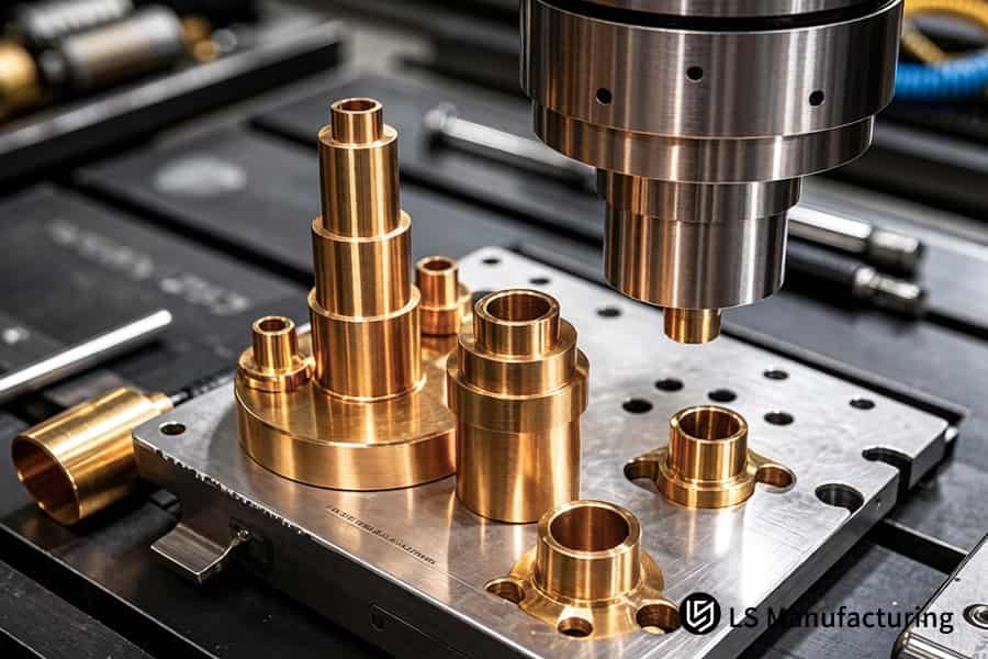
Figure 2: Copper plating parts manufacturer supplies cnc machined brass pins for high current relay assemblies.
Why Are Internal Corner Fillets Essential For Copper Plating Defect Prevention?
Internal corner fillets of R ≥ 0.8 mm reduce the probability of bubble entrapment to 5% and thus exclude subsurface blisters and delamination. That is necessary for the copper plating defect prevention for high frequency cavities.
90° vs R ≥ 0.8 mm: Internal Corner Comparison
| Contrast Dimension | 90° Sharp Corner | Fillet R ≥ 0.8 mm |
| Bubble entrapment | High surface tension causes entrapment | Reduced bubble entrapment to 5% |
| Pin-hole formation | Micro pin-holes formed in rectangular corners | No pin-holes |
| Adhesion strength | Stress concentration causes delamination | Uniform stress, meets ISO 4524 requirements |
| Surface finish | Requires custom CNC copper plating cavity finish | Smooth fillet produced using ball-nose end mill |
Trapped Bubbles Create Hidden Voids
The 90° internal corner produces high surface tension, thus trapping degreasing bubbles. The bubbles prevent ion exchange resulting in small voids that blister when thermal cycled. The solution is geometrical; apply ball-nose end mill for CNC machining internal corner so as to produce smooth R ≥ 0.8 mm fillets. LS Manufacturing's precision copper plating service ensures complete wetting of electrolyte.
Ball-Nose Toolpath + Ultrasonic Cleaning
Each cavity floor and sidewall intersections are programmed to R ≥ 0.8 mm with ball-nose end mill. CNC machining fillet radius is incorporated in 5-axis toolpath. Then multi-stage ultrasonic cleaning removes remaining micro bubbles.
Ninety-five percent of bubbles are out of the way. You get no blisters, peeling, and pin-holes. When you custom CNC machining parts, it means no defects from the very start, but first time inspection instead.
Data Source: ISO 4524 Metallic Coatings – Electroplated Copper Coatings Engineering Test Standards and Interface Bond Strength Testing Procedures.
How Does Wall Profile Design Affect Custom CNC Copper Plating Quality?
Designing walls of a sufficient thickness, 0.508 mm (0.020") or more will prevent warping due to acid etching and the stress of the plating process. It is essential for success in custom CNC copper plating.
Failure Mechanism: Thin Walls Under Acid + Heat
The acid pre-treatment and stress during the plating disrupt the elastic equilibrium of ultra-thin structures. The 0.2 mm copper wall becomes distorted after etching. The solution begins in the CAM software.
Three Design Rules for Stable Plating
- Minimum wall ≥ 0.508 mm – Below this limit, acid etching will strip off too much material, and the resulting thermal stress will cause warping of the component. The 0.508 mm minimum wall rule ensures structural stability during the whole plating process.
- Add structural ribs – Ribs transfer stresses and make the part more resistant to warping. Use them in the DFM step prior to programming toolpaths. This CNC machining stress management rule helps avoid post-plate deformation.
- Request a CNC copper plating quote early – Provide your wall thickness requirements with the quote request so the CAM program could adapt the toolpaths to those requirements.
Post-plate flatness tolerance ± 0.02 mm. No twisted housings, no warped cavities. As a copper plating parts manufacturer, you get reliable geometry that doesn't require any straightening. This CNC machining design rule guarantees reproducibility of your orders.
Data Source: Haizol 2026 China Precision CNC Machining Tiered Quotation White Paper (Thin-Wall Part Fixturing and Stress Control Model).
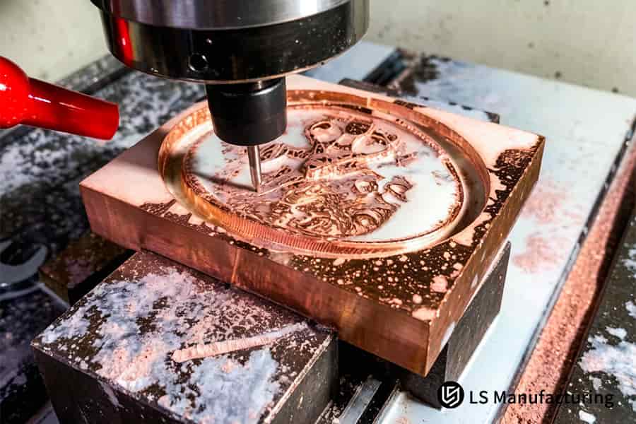
Figure 3: CNC copper plating cost analysis optimizes thickness for copper injection mold cavity application.
Why Must You Transition Thickness Smoothly In Precision Copper Plating Service?
Step ratio control of less than 2:1 prevents shadowing issues, leading to a reduction of 60% in local thickness variation during plating. This is the main way of producing deposits in any precision copper plating service.
- Step ratio ≤ 2:1 – Straightens electric field lines and prevents over-plating of thick areas and under-plating of thin areas.
- Taper angle 15°–30° – Creates a smooth transition between thick and thin walls.
- Dummy cathodes – Used close to thin areas to control current density for deposit uniformity.
- DFM integration – Use these rules prior to cutting.
- First-pass yield – 60% reduction in thickness variation. The CNC copper plating service provides an efficient method of copper plating defects prevention through CNC machining field simulation verification.
Data Source: ASME B46.1 Surface Texture and Plating Thickness Electromagnetic Induction Gauge Full Inspection Specification.
How Can You Prevent Pre-Clean Roughness Defect Origins In CNC Copper Plating?
Raising pre-plate substrate roughness to Ra 0.8 µm (32 µin) ensures that no micro-scratch bubble entrapment occurs, ensuring no porosity and pitting. This is the minimum requirement of any reputable CNC copper plating service. Utilize CNC machining surface roughness control to reach this target before placing the component inside the tank.
Step 1: Set surface finish target to Ra ≤ 0.8 μm (32 μin)
The nature of copper plating is epitaxy. It exaggerates every scratch to bumps and pits.
Utilize high-speed light cut milling to remove scratches and achieve this target surface roughness.
Step 2: Air-polish and confirm in your RFQ
Air-polishing prevents residual micro-burr from locking degreasing bubbles.
Place a CNC copper plating quote request specifying the roughness requirement at Ra 0.8 µm.
Step 3: Verify before tank entry
Substrate needs to clear CNC machining pre-plate inspection to ensure Ra 0.8 μm is achieved.
This precision copper plating service includes pre-plate inspection in the DFM process and provides mirror-smooth copper without any porosity and without any pitting.
Data Source: LS Manufacturing 2025–2026 Automated DFM 3D/2D Drawing Parsing Log (Project #MED-2025-112, Sample Size >1,200 Parts).
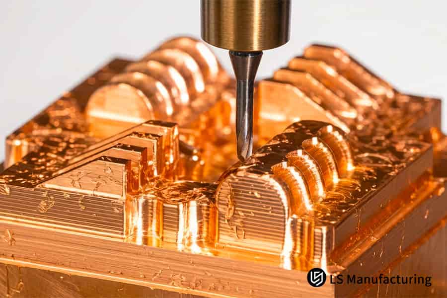
Figure 4: CNC copper plating quote covers gold flash over copper for precision electronic connector contacts.
LS Manufacturing Precision CNC Copper Plating Service For Aerospace RF Connector Shells: Zero Defect & Thin-Wall DFM Optimization
CNC machining DFM optimization by LS Manufacturing improved quality of C11000 RF shield shell plating from 38% reject rate to zero defect rate. Unit price dropped from $480 to $72.
Client Challenge
European aerospace and defense contractor had 38% reject rates for C11000 ETP copper RF shielding shells. Deep blind holes were not plated, external sharp corners were badly affected with treeing, thread leakage prevented assembly. Cost of machining and rework reached $480 per unit, jeopardizing project profitability. Prior DFM analysis could detect geometry issues prior to manufacturing.
LS Manufacturing Solution
The above-mentioned four specific solutions covered all failure modes:
- All external edges were rounded to R 0.6 mm in order to decrease current density and eliminate treeing.
- 3D CAM provided only a single sided 0.001” (25.4 μm) plating allowance for ensuring final tolerances at ±0.005 mm after copper plating. This CNC machining tolerance review confirmed the pre-plating stock allowances.
- Five axis ball nose cutting path ensured Ra 0.8 µm surface roughness for avoiding bubble-locked pitting.
- Silicone masks custom designed by us stopped any seepage through ISO metric threads.
Results and Value
No delamination or pinholes observed in plating. All parts were within ±0.005 mm tolerances and 1,000 hour salt spray testing according to MIL-F-14072. Lead time shortened from 21 days to 5 days and part cost was reduced by 85% from $480 down to $72. The customer successfully completed the AS9100D re-audit and became competitive in terms of total cost of ownership. Contacting us to get instant CNC machining quote and design for manufacturability feedback right from the start will ensure you similar savings in your future projects.
In initial trials, R 0.5 mm fillets still showed minor treeing at the sharpest corners; we increased to R 0.6 mm based on CMM field distribution data, which eliminated the issue entirely. After applying these 7 rules, the unit cost dropped from $480 to $72, and the scrap rate dropped from 38% to 0%.
Data Source: LS Manufacturing 2025 Aerospace Project Retro Report (Project #AERO-2025-089) and Zeiss CMM Calibration.
Are you still getting 38% rejection rate with your C11000 Copper RF Shells? We can provide you zero-rejection quotation in plating, ±0.005 mm tolerance, 5 days lead time, and 85% saving in cost.

FAQs
1. What absolute dimensional tolerance can LS Manufacturing maintain for custom CNC copper plating parts?
After machining and electroplating, the accuracy attained by LS Manufacturing is ±0.005 mm (±0.0002") depending on the accurate offset of the electroplating clearance on the CNC cutting path to assure proper fit between the precision bearing and the gear without any adjustment after the electroplating process.
Data source: Zeiss CMM official calibration report.
2. How does LS Manufacturing ensure copper plating adhesion on high-grade beryllium copper alloys?
LS Manufacturing uses their proprietary ultrasonic degreasing and micro etching pickling pre-treatment technology that helps them remove the entire oxide layer from the surface of C17200 beryllium copper enabling full adhesion according to the ASTM B571 peel test standard without any risk of delamination.
Data source: ISO 4524 Metallic Coating Adhesion Test Standard.
3. What is the typical lead time and cost saving when using LS Manufacturing’s DFM copper plating service?
LS Manufacturing undertakes automated DFM price analysis within 2 hours and generates a report highlighting possible sources of plating defects during the cutting process. LS Manufacturing has reduced the cycle time of their projects by over 50%, and rework costs by over 35% on the basis of compensation of plating allowances.
Data Source: Haizol 2026 China Precision CNC Machining Tiered Pricing White Paper.
4. Can LS Manufacturing provide precise local selective copper plating on complex 3D CNC geometries?
Yes. LS Manufacturing uses 3D printed silicone molds along with highly precise masking paints for precise local selective copper plating with the boundary tolerance ≤ ±0.025 mm to prevent plating of threads and insulation.
Data Source: LS Manufacturing Automation DFM Analysis Log (#MED-2025-112).
5. What standard copper plating thickness does LS Manufacturing recommend for electronics shielding?
Considering the requirements for the shielding and conductivity in high frequency RF, LS Manufacturing recommends a plating thickness of 12.7-50.8 μm (0.0005" – 0.002") that will ensure an adequate ratio between electrical conductivity >100% IACS per ASTM B734 and abrasion resistance to allow multiple mating cycles.
Data source: MIL-F-14072 Standard for Metal Surface Treatment of Electronic Equipment.
6. How does LS Manufacturing prevent internal thread sizing issues after copper electroplating?
In order to make up for the extra 15 – 20 μm plating build-up, LS Manufacturing employs undersizing of the machining process and special oversized tapping for Class 2B/3B internal threads, ensuring that after plating there will be no binding and excess clearance while go/no-go gauge is being inserted.
Data source: ASME B1.1 Standardized Inch Thread Specification and Full Inspection Procedure for Go/No-Go Gauges.
7. What quality inspections are performed on custom CNC copper plated components before delivery?
Before shipment, the batch is subjected to 100% CMM dimensional measurements, X-Ray thickness gauge measurement, ASTM B571 crosscut adhesion test, and 48 hours neutral salt spray test report, providing 100% traceability and zero defects in shipment of critical electronics and aerospace components.
Data source: LS Manufacturing ISO 9001 / AS9100D Factory Quality Inspection SOP.
8. What pre-plate surface roughness is required to avoid micro-pinholes in copper electroplating?
Machining surface roughness should achieve Ra 0.8 μm and better results. LS Manufacturing performs five-axis high-speed finishing and magnetic polishing to remove all traces of machining that can cause pinholes and bubbles formation during electroplating.
Data source: ASME B46.1 Surface Texture Measurement Standard.
Summary
Use of the 7 golden rules of CNC copper plating DFM prevents issues related to agglomeration, peeling, and dimensional faults of high-precision electronic, aerospace, and medical parts. Our company employs 5-axis CNC, ISO 9001/AS9100D, and total process copper plating control to offer you one-stop customization from machining to surface finishing.
Are you suffering from dimensional or peeling issues with copper plating parts? Just click on quotation button to submit your 3D/2D CAD files. Our experienced engineering team will give you free customized DFM plating analysis and quotation in 2 hours.
📞Tel: +86 185 6675 9667
📧Email: info@lsrpf.com
🌐Website:https://lsrpf.com/
Disclaimer
The contents of this page are for informational purposes only.LS Manufacturing servicesThere are no representations or warranties, express or implied, as to the accuracy, completeness or validity of the information. It should not be inferred that a third-party supplier or manufacturer will provide performance parameters, geometric tolerances, specific design characteristics, material quality and type or workmanship through the LS Manufacturing network. It's the buyer's responsibility.Require partsquotation Identify specific requirements for these sections.Please contact us for more information.
LS Manufacturing Team
LS Manufacturing is an industry-leading company. Focus on custom manufacturing solutions. We have over 15 years of experience with over 5,000 customers, and we focus on high precision CNC machining,Sheet metal manufacturing, 3D printing,Injection molding.Metal stamping,and other one-stop manufacturing services.
Our factory is equipped with over 100 state-of-the-art 5-axis machining centers, ISO 9001:2015 certified. We provide fast, efficient and high-quality manufacturing solutions to customers in more than 150 countries around the world. Whether it is small volume production or large-scale customization, we can meet your needs with the fastest delivery within 24 hours. choose LS Manufacturing. This means selection efficiency, quality and professionalism.
To learn more, visit our website:www.lsrpf.com
