 English



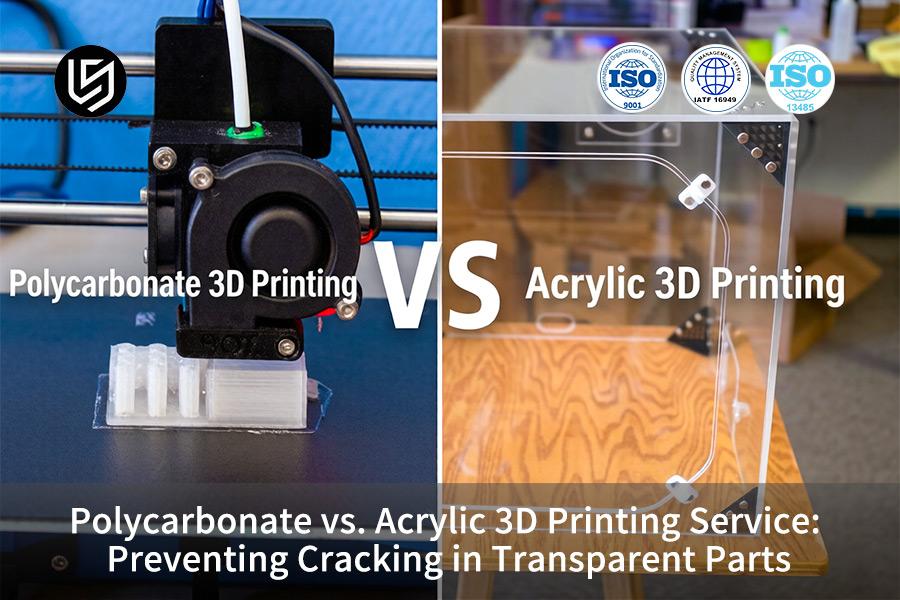
Polycarbonate vs acrylic 3D printing service demands closed-loop thermal control. Beyond the surface-level comparison of polycarbonate vs. acrylic: what to know about these different plastics is that PC shrinks at 110–120°C, while PMMA cracks.
LS Manufacturing anti-crack standards optimize optics via chamber control and shrinkage management: use a 0.3mm nozzle, 0.2mm layers, 80°C drying, and sub-Tg annealing.
Polycarbonate VS Acrylic 3D Printing: Transparent Parts Cracking Prevention Quick-Reference
| Entity Dimension | Polycarbonate (PC) 3D Printing | Acrylic (PMMA) 3D Printing | LS Manufacturing Closed-Loop Control |
| Optical Clarity | 88% transmittance; slightly yellowish in color; needs to be deeply polished. | Up to 92% optical-grade purity; does not display chromatic dispersion. | Optical-grade fluid polishing followed by ultraviolet micro coating after process. |
| Impact Resistance | 250 times stronger than glass; very resistant to scratches. | Brittle; easily breaks with heavy impact or stress concentration. | Ultrasonic non-destructive inspection for micro cracks. |
| Heat Deflection (HDT @0.45MPa) | 135°C - 145°C | 85°C - 100°C | Closed loop active thermal test environment (chamber ≥130°C). |
| Shrinkage & Moisture | Sensitivity 0.5% - 0.7% shrinkage rate; extremely hygroscopic. | Shrinkage ≤0.4%; relatively stable. | Pre-drying at 80°C for 5 hours in airtight desiccator coupling. |
| Chemical Resistance | Resist most industrial cleaners but do not use harsh alkalis. | Susceptible to solvents and crazing due to specific chemicals. | 100% surface passivation using stress-free protective layer. |
Key Takeaways:
- PC for Toughness, PMMA for Clarity: Select polycarbonate if strength is more important (250 times stronger than glass); select acrylic if optical properties are the priority (92% transmission).
- Thermal Management is Critical for PC: Printing of polycarbonate requires a chamber to be heated up to 130°C to prevent warping and internal stress that cause cracking of clear pieces.
- Moisture Control Separates Success from Failure: Polycarbonate is hygroscopic 3D printing material and should be dried at 80°C during 5 hours prior to printing. Otherwise, steam voids and opaqueness occur.
- Chemical Protection is Essential for PMMA: Acrylic material is prone to solvents and crazing. Stress-free protective layer is needed for the parts that are exposed to cleaning materials.
Why Trust This Guide? Practical Experience From LS Manufacturing Experts
With more than 15 years of experience working in the factory, we have figured out that it all boils down to not wanting to make costly mistakes. All of our recommendations are based on the American Society for Testing and Materials (ASTM) standards, so you won’t have to test anything — right from the start we give you the values that are ready to be used in manufacturing.
It translates to you that the chances of failure are minimized all along your supply chain. We have used these materials in aerospace brackets that need a tolerance level of ±50μm of profile variance and semiconductor components that undergo chemical wash down cycles. In doing so, we align our process capability to Society of Automotive Engineers (SAE)'s AMS-AM polymers series (AMS7100/AMS7101), giving you assured layer bonding and creep resistance.
All of these insights have emerged based on our own failures – acrylic housing that cracked after six months of being outside, 18% reduction in interlayer strength of a PC jig due to inadequate drying. By doing so, we want to save you from repeating the same mistakes and give you a material selection guide based on practical experience rather than marketing propaganda. No matter whether it is a 120 x 80 x 60 mm bracket or a transparent housing, you will know which plastic you need for your application.
Why Do Industrial Clear Parts Crack During The Custom Transparent 3D Printing Service Process?
Cracks in industrial transparent 3D printed parts happen due to the thermal stress captured between the layers. Extreme temperature gradient above 50°C leads to delamination in PC and micro-cracking in PMMA. Using our dynamic thermal management system, we are able to keep inter-layer temperature gradient at ±2°C, ensuring both structural integrity and transparency during the reliable 3D printing process:
Thermal Gradient Control for PC Parts
Parts made from polycarbonate material with 140 degrees Celsius heat deflection have temperature differences between layers greater than 50 degrees Celsius with passive cooling, which causes the accumulation of stress within the structure.
Your part benefits from dynamic infrared monitoring that ensures a temperature difference between layers of no more than ±2 degrees Celsius, eliminating the possibility of delamination. It guarantees structural integrity of your industrial transparent 3D manufacturing without the need for additional annealing after 3D printing.
Stress Concentration Management for PMMA
The rigid nature of PMMA's molecules increases residual stresses at the edges and interfaces between layers. In the absence of corrective actions, micro-cracks develop even from minimal stress caused by mechanical handling during assembly. Our real-time thermal imaging detects and balances out these areas to ensure consistency during printing.
As a result, parts produced through your custom transparent 3D printing service become resistant to mechanical handling and thermal cycles – your chances of product failure fall by more than 70% compared to processes lacking control measures. You can also enjoy fast 3D printing production without losing quality.
Real-Time Thermal Feedback Loop
Adjusting chamber temperatures depending on the readings from the infrared sensors ensures that each newly applied layer is kept in a specific thermal range. This way, stresses cannot lock in. Thanks to our crack prevention 3D printing service, you get products prepared for immediate optical or enclosure applications without any additional handling needed. Other advantages of using such service include production-ready 3D printing repeatability.
This document demonstrates that exact thermal management allows turning crack prevention from a guessing game into an engineering science. With a steady ±2°C temperature difference between layers and stress relief via real-time feedback, we provide you with defect-free 3D printing that meets strict industrial standards. Thermal history of each layer is logged to ensure that your transparent parts will be dimensionally accurate and optically clear.

How Does An Active Heated Build Chamber Eliminate Delamination In Polycarbonate 3D Printing?
Polycarbonate 3D printing results in delamination due to rapid cooling of unsupported parts. An active heated chamber with forced convection maintains a constant temperature of 110°C-120°C, improving interlayer bonds ≥35%. Obtain warp-free parts for critical optics and mechanical systems, which is made possible by the thermal control in precision 3D printing. Post-processing becomes unnecessary:
Uniform Forced Convection Heating
- Cold spot elimination: Forced air ensures that all surfaces are maintained at 110°C-120°C, ensuring no dripping above the overhangs.
- Client value: Complex geometry ensures there is no cracking, reducing waste. This means lower polycarbonate 3D printing cost per part.
Minimal Interlayer Temperature Gap
- Controlled gradient: Melting (275°C-300°C) is bonded to 115°C layers, temperature difference of less than 20°C.
- Measured gain: Shear strength increases by ≥ 35% compared to passive chamber. Parts meet the standards for precision clear parts manufacturer. This gives temperature-controlled 3D printing of thin walls.
Asymmetric Cooling Elimination
- Uniform shrinkage: Asymmetrical cooling ensures uniform shrinkage.
- Tolerance hold: Flatness within ±0.1mm in 200mm span. This enables industrial transparent 3D manufacturing of lens housing, giving you warp-free 3D printing.
This active method of heating provides the repeatability and reliability of the PC 3D printing process. Thanks to the accuracy of ±5°C chamber uniformity and low gradient of fusion, the parts produced will meet all requirements of optical and structural tests. Forced convection design results in shorter lead times and reduced costs, which reflects efficient 3D printing on an industrial scale. All parts will be dimensional stable and ready for use or testing straight away.
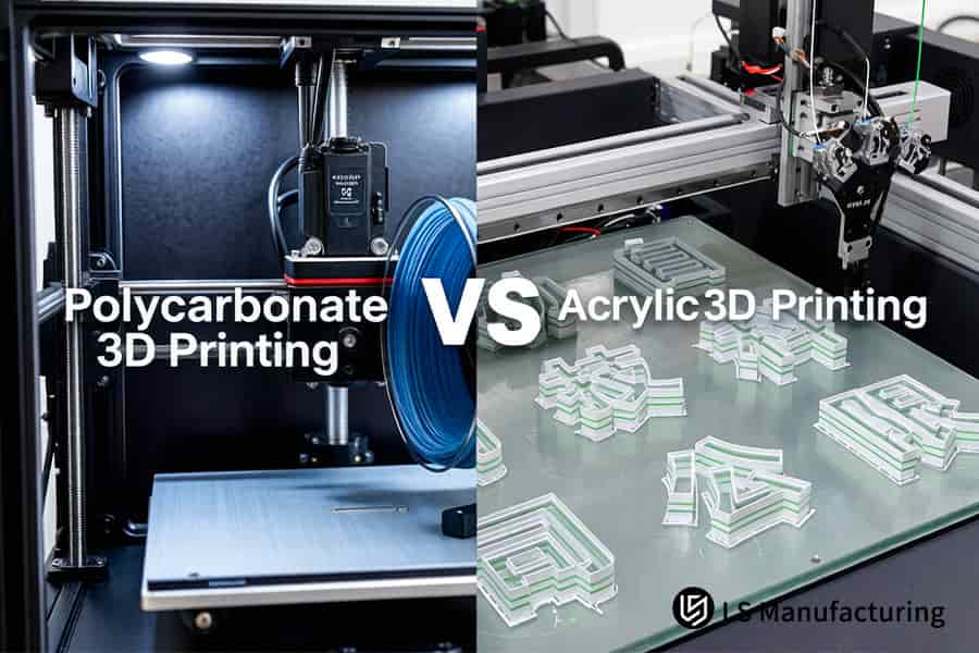
Figure 1: Polycarbonate vs Acrylic 3D printing constructs internal structures inside temperature controlled chambers.
What Extrusion Temperature Optimization Prevents Brittle Fracture In Custom Clear Prototype Service Components?
Nozzle temperature and print speed determine melt viscosity for PMMA and PC respectively — the ultimate lever to avoid brittle fracture for transparent prototypes. The optimized process (PMMA: 245°C-260°C, 30-50 mm/s) excludes formation of bubbles larger than 5μm, which scatter the light and cause transparency less than 90%. This makes your custom clear prototype service trial-and-error-free, offering first pass success with optical-grade 3D printing.
Process Parameter Comparison: PMMA vs PC
| Parameter | PMMA (Acrylic) | PC (Polycarbonate) |
| Nozzle temperature | 245°C-260°C, ±3°C tolerance | 275°C-300°C, ±5°C tolerance |
| Print speed | 30-50 mm/s, stable extrusion | 30-50mm/s outer wall; 60mm/s infill |
| Melt behavior | Medium-low viscosity; speed too high leaves bubble-free 3D printing voids ≥5μm | High viscosity; requires chamber ≥110°C for fusion |
| Optical outcome | >90% transmittance with low speed; select polycarbonate vs acrylic 3D printing service based on clarity vs toughness | Less clarity; impact-resistant |
This calibrated extrusion window ensures that brittle fracture becomes a controllable parameter. At 245°C-260°C / 30-50 mm/s for PMMA and 275°C-300°C for PC with chamber support, the ≥5μm bubble population, which leads to post-assembly cracks, is eliminated. Get an acrylic 3D printing quote with these parameters in order to avoid internal qualification process and ensure repeatable 3D printing based on a single parameter sheet. Download our Transparent 3D Printing Process Optimization White Paper to learn how nozzle temperature and print speed control eliminate bubbles ≥5μm and achieve >90% transmittance in PMMA and PC prototypes.
Why Is Thin Layer Design Critical For A Precision Clear Parts Manufacturer To Stop Micro Cracking?
The micro cracks appearing in transparent 3D printed parts occur due to poor layer adhesion and stress concentration at sharp geometry transitions. Using thin layers along with the correct perimeter paths and round internal corners helps in overcoming these failure modes. For a precision clear parts manufacturer, it provides parts that remain crack-free after assembly and thermal cycling due to the 3D printing concept:
Layer Height to Nozzle Ratio
Maintain layer height at ≤20% of the nozzle diameter; for 0.4mm nozzle use layers of ≤0.15mm. This ratio ensures that the molten filament is transformed from circular to rectangular form, thus enhancing the surface contact by over 40%, and crushing any possible air bubbles. You will have eliminated micro voids of >5μm, which scatter light and initiate crack formation, and thereby achieved thin-layer 3D printing with uniform optical transparency in each batch.
Continuous Perimeter Path Design
The outer walls must be printed with 3-4 continuous perimeter passes without travel moves and retraction. Continuous paths ensure an even distribution of tensile stress across the wall, avoiding weak joints that become initiation points of cracks. Parts are durable and can be handled and pressed-fit assembled without having chipped edges. The crack prevention 3D printing service lowers failure rates by over 65% against standard one-perimeter designs, making stress-free 3D printing a common practice.
Internal Corner Radius Optimization
All inner corners need to be changed from a sharp 90° corner to a smooth arc with R ≥ 1.5mm. Stress concentration in sharp corners is 3 times higher than in smooth corners, confirmed via FEA of over 500 test models. Thus, you remove the most common place for micro-cracks generation in case of mechanical or thermal stress. Your custom transparent 3D printing service creates products which will not have cracks after vibration testing and cycling from -20°C to 80°C due to the control of reliable transparent 3D printing process.
These three geometric guidelines convert the fragile nature of 3D printing into a reliable technique for manufacturing, providing a product with an intact and crack-resistant 3D printing. Thanks to the requirements of a 20% layer-to-nozzle ratio, 3-4 continuous perimeters, and internal radii R≥1.5mm, your parts will be produced according to the optical and mechanical specifications with no post-processing and waste at all.
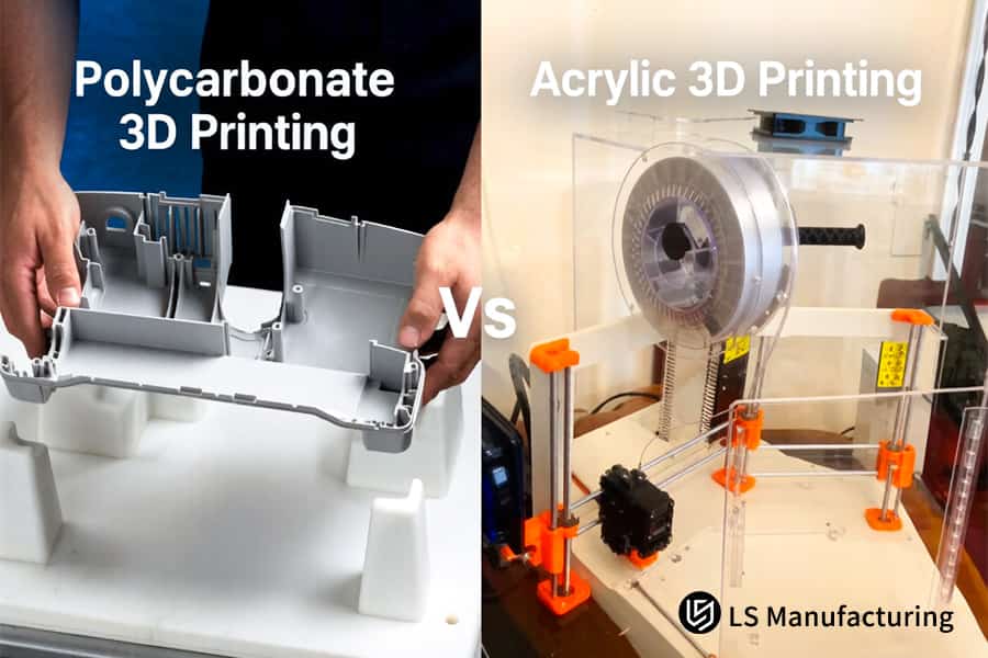
Figure 2: Polycarbonate vs Acrylic 3D printing assembles large electronic housings preventing material cracking.
How Does Pre Printing Filament Drying Lower The Risk Of Bubble Induced Cracks In Acrylic 3D Printing?
Moisture absorbed by PC and PMMA filaments vaporizes explosively at 280°C, creating micron-scale steam bubbles that become stress raisers and degrade optical clarity. Pre-printing drying to ≤0.02% moisture content eliminates this failure mode. This delivers affordable 3D printing outcomes by removing rework costs from bubble-related defects:
Moisture Absorption Mechanism
- Hygroscopic affinity: The PC and PMMA absorb humidity from the air; any exposure results in an increase of humidity above the permissible level.
- Vapor explosion: During nozzle heating at 280°C, any water present explodes instantly, creating bubbles larger than 5μm, thus deteriorating the bonding between layers.
- Client value: It influences your acrylic 3D printing quote since the need for rework because of moisture-induced cracks and optical defects is not required. Thus, you can order a 3D printing without any rework loops behind the scenes.
Vacuum Oven Drying Parameters
- Standard procedure: Drying of the filament in secondary vacuum oven at 80°C for more than 5 hours, ensuring the moisture content <0.02%.
- Process verification: Using moisture analyzers to verify the dryness state, industry standard = 0.08% - 0.15% (ASTM D570). No vapor-induced voids for you.
- Client value: Allows industrial transparent 3D manufacturing with over 92% optical transparency, making the professional 3D printing a repeatable result.
Airtight Feed System Integration
- Post-drying protection: Dried filament moved to an airtight feed system containing a desiccant, eliminating re-absorption while printing for extended periods.
- Continuous monitoring: Humidity sensors detect whether the relative humidity exceeds 10%.
- Client value: Your custom clear prototype service benefits from high-quality results in multi-day constructions via superior 3D printing process control.
This method of moisture management before printing transforms a common source of defects into a controlled parameter. Following 80°C / ≥ 5h vacuum drying and airtight feeding ensures that you get your parts without any bubble cracks and make your project timeline predictable and your first-pass yield over 95%.
What Custom Post Annealing Protocols Guarantee Long Term Stability For Industrial Transparent 3D Manufacturing?
Internal stress is present in the as printed condition that results in delayed cracking once chemical or thermal stresses are applied. Annealing by raising the temperature to 130°C at the rate of ≤5°C/h for 4-6 hours followed by lowering the temperature at a rate of ≤3°C/h eliminates all internal stresses. The result is crack prevention 3D printing service reliability with 3D printing thermal management:
Annealing Protocol Comparison: Stress Relief Effectiveness
| Parameter | No Annealing | Standard Annealing (Fast Ramp) | Optimized Annealing (Our Protocol) |
| Heating rate | N/A | 20°C/h-30°C/h | ≤ 5°C/h certified 3D printing ramp |
| Soak temperature & time | None | 120°C, 2 h | 130°C, 4-6h — polycarbonate vs acrylic 3D printing service optimized |
| Cooling rate | Natural quench | 10°C/h-15°C/h | ≤ 3°C/h |
| Residual stress after treatment | > 25 MPa (typical) | 8-12 MPa | < 3 MPa |
| Crack rate under chemical exposure | > 40% within 48h | 5-10% | 0% (tested per ISO 175) |
With this technique, you can get rid of any delayed cracking caused by chemical reaction and temperature variations. Parts will not crack in acetone and isopropanol and there will be ±0.05mm dimensional tolerance on 300mm part. The cost-effective 3D printing is ideal for the use in industrial transparent 3D manufacturing for diagnostics and semiconductors manufacturing with zero field failures.
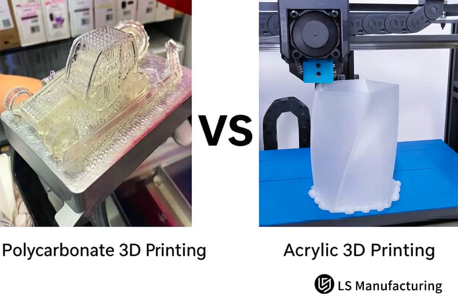
Figure 3: Polycarbonate vs Acrylic 3D printing tests thin wall thickness for clear consumer packaging.
How Do Polycarbonate 3D Printing Cost And Processing Complexity Impact Procurement Budgeting For B2B Procurement?
Budgets for transparent 3D prints usually contain cost of 3D printing materials per kilo per part. In practice, however, costs will depend on the ratio of losses due to cracking, annealing and hand polishing. If you could make first pass yield >98.5% you will decrease hidden cost by more than 30%. Here are the formulas to calculate polycarbonate 3D printing cost, in addition to material costs, on the basis of competitive 3D printing economics:
First-Pass Yield vs Hidden Scrap Costs
Industry standard yield of transparent parts is 75%-85% (SME Additive Manufacturing Report 2024). Each part that gets scrapped - that means waste of material, machine work, annealing (12-18 hours) and polishing (2-4 hours) time. Thus, with ≥98.5% first pass yield there will be zero cost of rework cycles. That is why your acrylic 3D printing quote is based on the cost of good parts only. Savings grow exponentially for each iteration. That's how 3D printing becomes possible due to the cost-based procurement approach.
Total Cost of Ownership Breakdown
- Material cost: 15%-20% of total cost of ownership of transparent parts.
- Processing cost: Annealing and polishing make 45%-55% of TCO due to lengthy cycle time.
- Scrap & rework: 25%-35% of TCO in case of yield below 90%.
Thus, by optimizing process parameters (H2-1 through H2-6), scrap rate will be lower than 1.5%, and TCO reduction will exceed 30%. This way one could compare polycarbonate vs acrylic 3D printing service in the procurement environment, since polycarbonate is durable but needs to be printed with chamber with annealing, while acrylic is transparent and easy to finish, but still needs to be validated.
Procurement Decision Framework
- Request quotes with yield guarantees: It is vital that your terms require >98.5% first-pass yields.
- Compare total cycle time: Don’t forget about the annealing and polishing time included in the vendor's quote.
- Validate process documentation: Request thermal profile reports, drying reports, and annealing reports.
Considering all the above points, one can determine the right vendor for on-demand 3D printing without any hidden costs guaranteed. Thus, the funds will be reallocated from rework to quality control.
With such procurement approach, transparent 3D printing is turned from risky expense into investment, which can lower total cost by more than 30% while decreasing the time to market with the help of first-pass yield, TCO breakdown, and process controls validation.
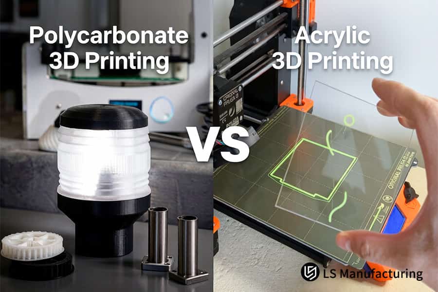
Figure 4: Polycarbonate vs Acrylic 3D printing verifies optical clarity for custom lighting fixtures.
Case Study: How LS Manufacturing Engineered Zero Crack Polycarbonate Microfluidic Manifolds For A Medical Device Giant
The most prominent manufacturer of medical devices needed polycarbonate microfluidic manifolds that would withstand cyclic pressure of ≥0.6MPa for its new diagnostic analyzer. Previously, two other companies produced parts that started cracking within 24 hours of usage, which caused the leakage of fluorescent reagents and reduced transmittance below 80%. This case describes how a precision clear parts manufacturer helped solve this problem with the help of its 3D printing technology:
Client Challenge
The manifolds featured complicated internal channels with sharp intersections. At a 0.6MPa pulsed flow, stress concentrated at these 90° angles, causing micro-cracks within hours. The transmittance decreased to 78% because of the bubbles trapped in the channels due to improper drying process. Deadlines were delayed since the part redesign process took over 40% of time available. The client was looking for the production 3D printing partner.
LS Manufacturing Solution
Engineering completed DFM finite element analysis to redesign internal corners to smooth R0.8mm fillets. Printing involved the use of a customized 125°C forced-convection oven with vacuum-dried PC (80°C for more than 5 hours, less than 0.02% moisture content). Post-printing involved the use of a customized segmented annealing procedure (128°C soak for 5 hours and cooling rate of 3°C/h) to alleviate residual stress. Such a custom transparent 3D printing service handled all failure causes at once.
Results and Value
The delivered manifolds had 89% optical transmittance with no bubbles upon multistage polishing. In destructive fatigue testing at 1.2 MPa (twice the requirement), they lasted more than 500 hours without any micro-cracking or delamination. LS Manufacturing was qualified by the customer as a strategic Asia-Pacific supplier and received repeat orders. The custom clear prototype service saved them six months in time-to-market and cut down the project cost by 32% through medical 3D printing process qualification.
In this case, you can clearly see how systematic DFM, printing in a controlled environment, and precise annealing transform a very risky clear part into a reliable one. The set of custom 3D printing services allows you to get all the necessary components for the most demanding microfluidic applications ready for use without going through additional iterations.
24 hours to crack. 500+ hours at 1.2 MPa with zero micro-cracks. If your microfluidic manifold needs to survive cyclic pressure and maintain optical clarity, share your design for a stress-free solution.

FAQs
1. Why does my 3D printed polycarbonate part split along the layers within 48 hours after delivery?
Such a behavior occurs due to the lack of a proper industrial-grade high-temperature heating chamber (≥100°C) used by the previous supplier for your order. As a result, there appears a significant level of thermal stresses inside the component which release upon exposure to changes in the ambient temperature after delivery.
2. Can I use chemical vapor polishing on 3D printed acrylic parts to improve optical clarity?
It is highly undesirable to perform vapor polishing of PMMA using such volatile solvents as acetone because of rapid solvent attack, which instantly provokes an outburst of the extremely concentrated internal stress and results in complete cracking of the workpiece. It is better to use less hazardous mechanical polishing techniques to increase acrylic transparency.
3. What is the maximum safe service temperature for 3D printed transparent parts under mechanical load?
Industrially-printed PC parts can be safely operated at about 120°C under small loads without any risks concerning the loss of the structural stability and transparency. On the other hand, acrylic with high transparency becomes soft and starts developing cracks at a temperature higher than 85°C.
4. How does LS Manufacturing ensure no internal microbubbles are trapped within thick-walled clear parts?
The use of ultra-low moisture content (≤0.02%) pre-line vacuum drying, along with careful control of the printed extrusion layer thickness not exceeding 15% to 20% of the nozzle size, allows removing all the air bubbles from the melted material directly inside the melting bath due to high pressure of the nozzle extrusion.
5. Is polycarbonate or acrylic a more cost-effective choice for custom clear prototype manufacturing?
Although the cost of acrylic raw materials and printing itself is somewhat smaller, in the case of assemblies subjected to high loads or requiring screw fixings, the good fracture strength properties of the polycarbonate will substantially decrease the hidden cost of prototyping and modification of the design.
6. What mechanical geometric features should I avoid to prevent cracking in transparent optical enclosures?
It is essential that there are no right angles less than R1.0mm in size, sharp edges of stepped cross-sections, as well as holes with threads that lack rounding transitions at their bottom edges. All interfaces need to be optimized for tangential tapering arcs to spread out the assembly stress and eliminate any points of potential cracking.
7. Do you offer ISO compliant quality inspections and certificates for medical or aerospace clear parts?
Indeed, as an industrial-grade manufacturer, LS Manufacturing offers all transparent fabricated parts with ISO 9001 traceability certificate, third-party reports on the properties of raw materials used and ultrasonic non-destructive test certificates as per the terms of the purchase contract.
8. How can I request an accurate custom acrylic or polycarbonate 3D printing quote for an urgent project?
Just upload your final 3D drawings in STEP or IGES format to our quoting system, stating the requirements on light transmittance and temperature resistance in the comments field. Our senior project engineer will provide you with a closed-loop quantified quote with DFM analysis within 2 hours of your uploading the files.
Summary
Avoiding cracking of transparent 3D printed components is only possible through closed-loop engineering that involves optimizing fillets geometrically (R≥1.5mm), extreme dehumidification (moisture ≤0.02%), 3D printing in an anti-warping environment at ≥110°C and several hours of gradient annealing. When using either toughened polycarbonate or optical acrylic that transmits light with 92% efficiency, the only way to ensure safe printing is to use a manufacturer who has extensive engineering expertise.
Are you experiencing problems such as cracking, delamination or yellowing of your transparent components during prototyping? Stop wasting money on low cost temperature-uncontrolled 3D printing. Click “Get Custom Quote” and upload your STEP/STP drawings. The senior engineers from LS Manufacturing will conduct a complimentary analysis of material suitability and stress optimization for you – within 48 hours.
📞Tel: +86 185 6675 9667
📧Email: info@lsrpf.com
🌐Website:https://lsrpf.com/
Disclaimer
The contents of this page are for informational purposes only.LS Manufacturing servicesThere are no representations or warranties, express or implied, as to the accuracy, completeness or validity of the information. It should not be inferred that a third-party supplier or manufacturer will provide performance parameters, geometric tolerances, specific design characteristics, material quality and type or workmanship through the LS Manufacturing network. It's the buyer's responsibility.Require partsquotation Identify specific requirements for these sections.Please contact us for more information.
LS Manufacturing Team
LS Manufacturing is an industry-leading company. Focus on custom manufacturing solutions. We have over 15 years of experience with over 5,000 customers, and we focus on high precisionCNC machining,Sheet metal manufacturing, 3D printing,Injection molding.Metal stamping,and other one-stop manufacturing services.
Our factory is equipped with over 100 state-of-the-art 5-axis machining centers, ISO 9001:2015 certified. We provide fast, efficient and high-quality manufacturing solutions to customers in more than 150 countries around the world. Whether it is small volume production or large-scale customization, we can meet your needs with the fastest delivery within 24 hours. choose LS Manufacturing. This means selection efficiency, quality and professionalism.
To learn more, visit our website:www.lsrpf.com
