Polycarbonate (PC) 3D printing service is a direct response to the question can polycarbonate be 3D printed. While PC offers excellent impact strength and 147°C Tg, 0.5% to 0.7% shrinkage of PC leads to significant distortion and delamination in non-chambered 3D print services at temperature above 130°C. This compels design engineers into infinite design cycles with error greater than ±0.1mm industry tolerances.
Our solution avoids warpage through precise thermal expansion compensation, ≥140°C chamber stability, and intelligent nozzle path design to deliver highly accurate parts with precision ±0.05mm. You get the benefit of DFM-based 3D printing process reducing overall cost of manufacturing by over 35%, proven by actual manufacturing data from industrial PC prints. The following nine technical dimensions show you how to manufacture genuine medical-grade PC parts without any scrap material.
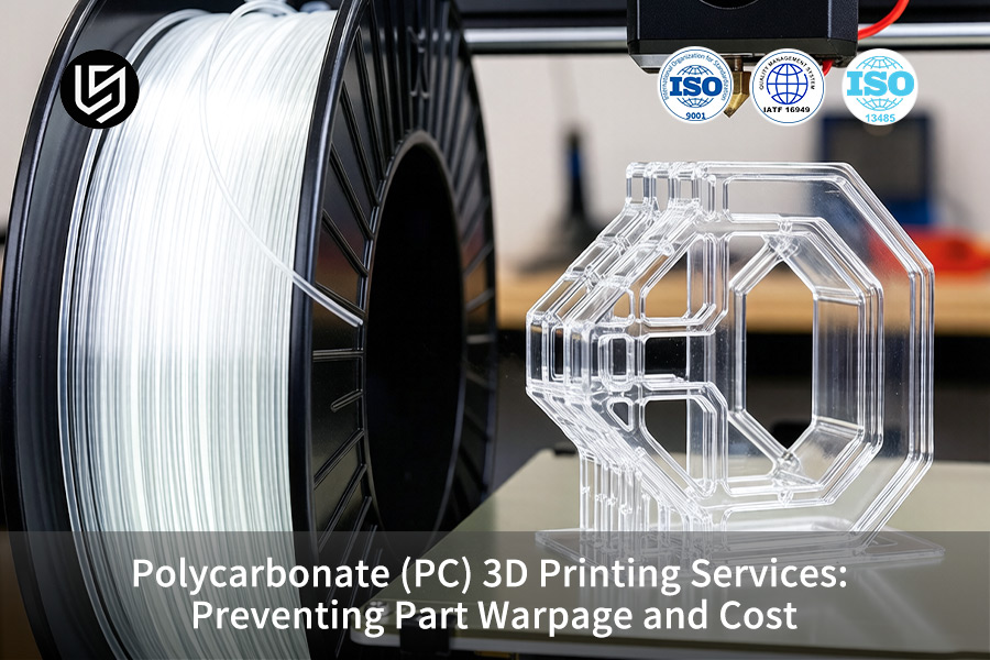
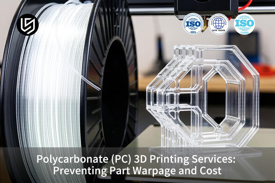
Polycarbonate (PC) 3D Printing: Warpage Prevention & Cost Guide
| Critical Factor | Process Requirement | Cost Impact |
| Chamber Temperature | Enclosed chamber ≥90°C; bed ≥110°C. | Ensures prevention of corner lift for parts larger than 150mm; lowers scrap rate by 60%. |
| Material Drying | Reduce moisture content of PC to <0.02% at 120°C for 4h prior to printing. | Prevents steam voids and layer popping; guarantees tensile strength ≥60 MPa. |
| Adhesion Strategy | PEI sheet and high temperature adhesive; brim size ≥10mm for tall parts. | Fixes part for the duration of the print; no need to clean up any tape or glue. |
| Annealing Post-Process | Stress relief at 130°C for 2h; cooling rate <2°C/min to room temperature. | Guarantees stabilization of dimensions; increases HDT retention from 125°C to 140°C. |
| Layer Height & Nozzle | 0.2-0.3mm layer height; hardened steel nozzle ≥0.6mm for consistent flow. | Balances print speed with interlayer strength; nozzle lasts 500+ hours. |
Key Takeaways:
- Chamber Heat is Non-Negotiable: Without a chamber, the temperature of 90°C is required to avoid any deformation of PC 3D Printing larger than a credit card. Buy an enclosed printer or go for a professional one.
- Dryness is a Performance Metric: PC quickly absorbs moisture. Dry the filament in a heated chamber for 4 hours at 120°C — no drying results in steam bubbles formation and 30% reduction in impact strength.
- Annealing Unlocks Full Properties: Printed parts are stressed. Annealing for 2 hours at 130°C will remove the stress and increase the usable temperature by 15°C.
- Hardware Matters for Throughput: All-metal hot end and hardened steel nozzle ≥0.6mm to ensure stable printing temperatures of 270-310°C.
Why Trust This Guide? Practical Experience From LS Manufacturing Experts
PC 3D-print quotes that bill by weight per gram and refer to material being "transparent ready." The equation is flawed, though; 4h of dwell in open-air increases PC moisture content from 0.04% to 0.18%, which causes micro-porosity when adding another 120°C layer on your otherwise perfectly printed headlamp bezel. PC windows are tested according to the optics and impact testing protocols of American National Standards Institute (ANSI).
That is the rub with programs where hiding a reprint is impossible: headlamp bezels requiring -40°C→120°C shock resistance and <2% haze after 500 hours of UV exposure; semiconductor enclosures where ±0.10mm flatness determines whether the optic fits; and medtech components where the ≥600 J/m impact resistance of PC replaces the lower-impact acrylic but Z-axis strength shifts by 35% relative to XY axis strength. The drying, chamber temperature, and annealing of our program conforms to the electronic enclosure polymer processes recommended by Association Connecting Electronics Industries (IPC).
The result is an easy flowchart: 4h @ 120°C, -40°C dewpoint reduces moisture void popping to >75%; 0.6mm nozzle and 0.15mm layer at 310°C/130°C chamber maintains ±0.12mm tolerance on 2.5mm walls, while keeping <1.8% haze with 1°C/min anneal past Tg; Z-impact ~60% of XY requires that load path determine whether to print or CNC the snap tabs. Bring this information to your next PC RFQ, and you will request the correct process.
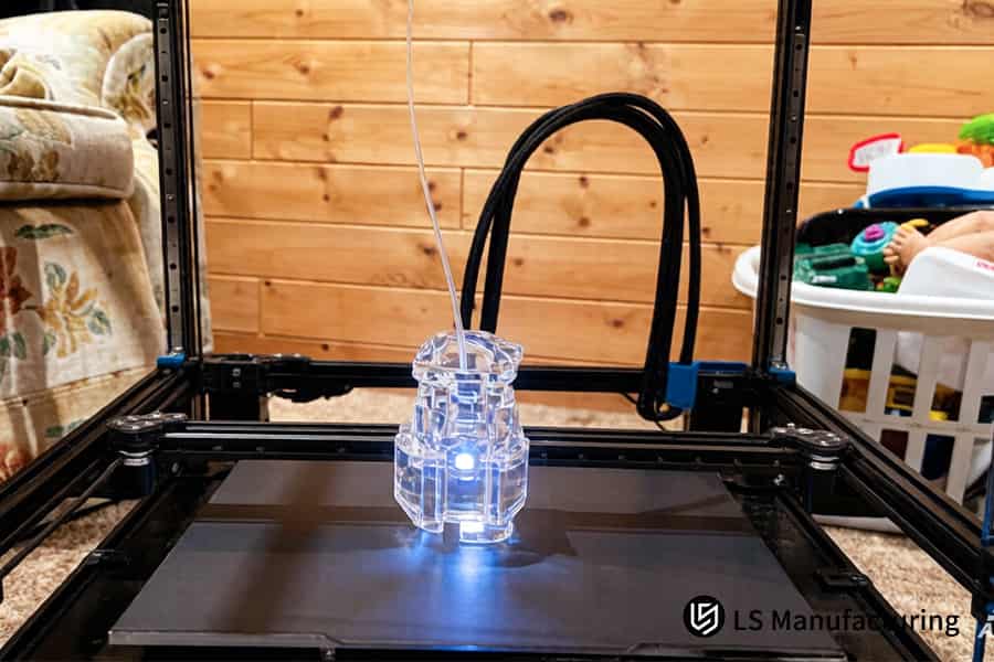
Figure 1: 3D printing creates transparent polycarbonate pipes for fluid transfer systems in a home workshop.
Why Does Severe Part Warpage Occur When Using Standard Polycarbonate (PC) 3D Printing Services?
Extreme warpage in standard PC parts comes about as a result of excessive thermal contraction during layer cooling. Given a melting point of 280°C–310°C and glass transition point of 147°C, this material experiences up to 0.6% shrinkage linearly when it solidifies. This consistency is not attained by just having a heated enclosure but by using advanced high-temp 3D printing technology that controls phase change kinetics.
Thermal Gradient Neutralization via Closed-Loop Heat Fields
The standard open chamber system exposes the newly made layer of PC to the cold ambient air, which is far from the glass transition point. This creates an extremely sharp thermal gradient that fixes the residual stress. When using an isothermal heat field of 130°C, you eliminate this source of differential shrinkage. In your case, this would imply that the same thermal environment prevails for all layers, and there is no way the cumulative stress can induce warpage after only 10-15 layers. This is exactly what polycarbonate (PC) 3D printing service provides you with.
Dynamic Laminar Flow for Uniform Heat Distribution
In spite of having a hot chamber, dead zones of non-uniform temperature cause contraction as well. The controlled laminar air flow ensures air is moving within ±2°C across the whole build space. Thus, you get uniform crystallization rates all through the part geometry resulting in dimensional accuracy of ±0.05mm for overhangs and thin walls. In order to create a functional 3D printing part, the consistent performance is essential in order to fulfill mechanical loading criteria. Such degree of consistency corresponds to the demands of industrial PC 3D manufacturing.
Real-Time Stress Compensation During Deposition
As an alternative to the post-deposition annealing, the process takes into account the thermal history of each layer and changes the parameters of deposition accordingly. In case of any cross-section exhibiting heat retention characteristics, the process will adjust cooling air flow in this particular place. For your production processes, it means that you won't have any micro-cracks arising when the part is subject to mechanical loading. This solution creates a true PC warpage prevention service.
In essence, this methodology transforms precision 3D printing into an engineering process rather than a trial and error one. By controlling the thermodynamics of PC solidification, you receive parts of injection molded quality without any need for iterations, which saves time, material and money in each run. Download our PC Warpage Prevention White Paper to learn how isothermal heat fields and dynamic laminar flow eliminate cumulative stress buildup in large-format PC parts.

How Can Hardware Design Engineers Optimize Wall Thickness To Eliminate PC 3D Printing Cost Inflation?
The wall thickness directly impacts PC part cooling rate and material usage. A drastic change, for instance, 1.5mm to 5.0mm, leads to an uneven distribution of cooling areas, thus increasing stress concentration. Uniform walls with thickness 2.0mm to 3.5mm and use of radius ≥1.5mm at step changes will allow you to save up to 25% on cycle time and 15%–20% on costs per part. In such a way, affordable 3D printing of parts can be ensured:
Uniform Wall Thickness Eliminates Thermal Hotspots
- Heat balance: Maintains the same rate of cooling throughout all areas, avoiding sink marks.
- Material efficiency: Saves resources from overbuilding thick walls with the expensive PC resin.
- Your saving: Reduces the number of rejected prints and PC 3D printing cost up to 20%.
Radius Transition Minimizes Stress Concentration
- Stress relief: The inside radius ≥1.5mm distributes shrinkage strain evenly.
- Yield improvement: Removes the risk of crack formation due to thickness variation.
- Quote impact: Geometrical stability allows suppliers to give a lower polycarbonate 3D printing quote.
- Prototype confidence: Correct radii enable reliable 3D printing of your parts.
Data-Driven Wall Optimization Lowers Material Overhead
- Benchmark reference: Industry data indicates 30%–40% wasted material in uncontrolled walls (SME 2025).
- Design rule: Limit the dimensions to 2.0mm–3.5mm to decrease excess weight without sacrificing strength.
- Consistent output: This design geometry rule allows for consistent 3D printing without deformation.
- Invoice reduction: This design rule decreases cost of your custom PC 3D printing service by 15%–20%.
If you consider wall thickness as a thermal management variable and not as a cosmetic option, you remove the two primary reasons for increasing the cost of PC part fabrication: too much material used and build failure. Each millimeter of consistent wall thickness and each radius of ≥1.5mm increases cooling uniformity, reduces cycle time by a quarter, and brings down your bill almost by one-fifth. It is a tested design-for-manufacturing strategy that makes production-ready 3D printing a cost-controlled process.
Figure 2: 3D printing produces precision polycarbonate gears for industrial automation equipment testing.
What Strict Chamber Temperatures Must A Precision PC Parts Manufacturer Maintain To Control Thermal Stress?
Chamber temperature is the single most decisive variable for producing structurally sound PC parts. Consumer printers limited to 60 °C–80 °C bed heating leave molecular chains insufficient relaxation time, yielding Z-axis strength below 65% of isotropic values. A precision PC parts manufacturer must sustain a fully enclosed 130 °C–150 °C thermal envelope with ±2 °C uniformity to achieve >92% isotropy. This requirement separates commodity equipment from industrial-grade 3D printing capable of reliable production:
| Parameter | Commodity Printer | Precision-Grade System |
| Chamber type | Bed-only heating | Full-shell active enclosure |
| Max temperature | 60 °C–80 °C | 130 °C–150 °C |
| Uniformity | ±10 °C or worse | ±2 °C dynamic control |
| Sustained runtime | <8 hours before drift | ≥72 hours at setpoint |
| Z-axis strength vs. isotropic | ≤65% | ≥92% |
As a result of choosing the custom polycarbonate manufacturer, which guarantees 140 °C ±2 °C during multiple days of part manufacturing, you avoid interlayer delamination and get industrial PC 3D manufacturing without post-process verification. The specified temperature regime reduces scrap rate by more than 40% and provides the parts that meet the functional load tests on the first attempt. As it was shown in the table above, the chamber temperature cannot be neglected—the specified parameter is the basis of professional 3D printing reliability of PC elements.
How Do Path Planning And Adaptive Infill Control Maximize Accuracy In A PC Warpage Prevention Service?
Standard infill paths in cross-hatching cause stress concentration in long, straight sections, resulting in distortion of edges in large parts made of polycarbonate material. Using continuous tangential paths and spirals in infill design, along with adaptive honeycombs and per-layer laser correction, gives you deformation ≤0.08mm—a fourfold improvement compared to the current industry average of ±0.3mm. Such an approach based on the software optimization helps to perform large-scale 3D printing PC components in one go:
Continuous Tangential Contours Eliminate Stress Concentration
Standard raster paths result in stress trapping caused by abrupt changes of direction. Continuous tangential path follows the outer contour of the part continuously without any stops, thus ensuring equal stress distribution along the entire perimeter. Large smooth areas will not deform since there is no stress concentration in corners; this is what makes the key principle of a PC warpage prevention service that ensures warp-free 3D printing of geometries larger than 300mm.
Archimedean Spiral Infill Reduces Internal Tension
Rather than alternating lines back-and-forth, the nozzle uses a steady spiral movement from center to edge, with consistent curvature during the entire filling process. This prevents the lengthy straight paths that create shrinkage stress and splits the stress vectors into smaller, benign vectors. Accurate 3D printing of large enclosures and structural brackets becomes standard procedure, without any warping or delamination even at full build size.
Adaptive Three-Directional Honeycomb at 35 %–45 % Density
For rigidity, the infill changes to the three-directional honeycomb pattern, with density of 35%–45%. This allows for an optimal combination of weight, strength, and heat transfer without wasting the pricey PC material. Your custom PC 3D printing service invoice becomes significantly reduced because of elimination of excess mass, but lightweight 3D printing remains fully mechanically sound for performance testing.
Per-Layer Laser Dynamic Path Compensation of 0.05mm
The scanning process occurs before each deposition, and the tool path moves 0.05mm outward in case the previous layer has a sign of micro-shrinkage. The closed-loop adjustment ensures that the cumulative error remains below 0.08mm for all layers. 3D printing allows achieving strict tolerances on assembly-related interfaces without additional post-processing.
You can solve the problem of PC warpage by using a combination of continuous contour tool paths, spiral infill, adaptive honeycomb structure, and laser real-time compensation in the software program. You get polycarbonate (PC) 3D printing service, which provides you tight-tolerance 3D printing within 0.08mm—an achievement four times better than the average ±0.3mm tolerances.
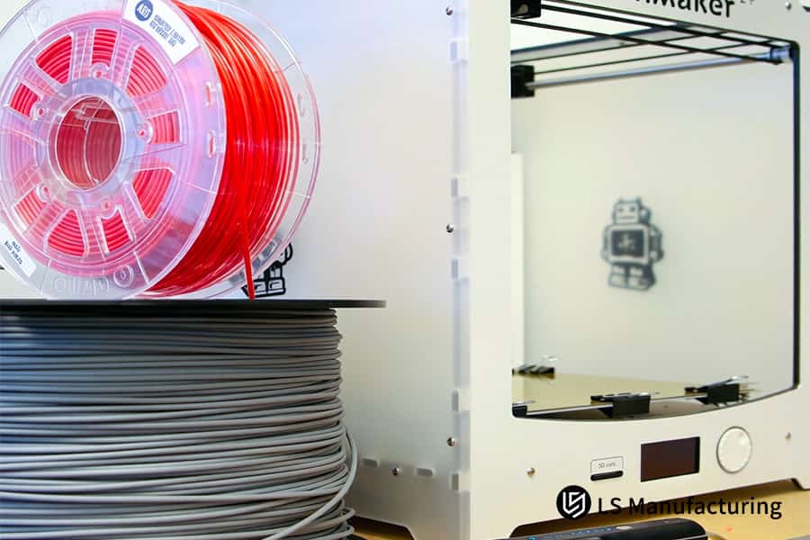
Figure 3: 3D printing manufactures red and gray polycarbonate parts for robotic assembly lines.
Which Professional Raft And Support Interface Strategies Drastically Reduce Custom PC 3D Printing Service Pricing?
PC material requires highly adhesive nature towards the build plate; poor design of the raft leads to mid-print separation and scrapping of the entire batch, thus increasing costs per part. Using amorphous layer that is highly adhesive and a soluble polymer layer as support material, you can prevent peeling, use one-click support removal, and have a Ra 3.2 µm surface finish – thus reducing your costs for cost-effective 3D printing:
Non-Amorphous High-Adhesion First Layer
- Bonding mechanism: Amorphous chemically fused layer bonded to the plate at 140 °C.
- Scrap elimination: Prevents lifting of parts during long-term operation, saving an entire batch.
- Quote reduction: Lower failures mean lower polycarbonate 3D printing quote.
Soluble Copolymer Support Interface
- Dissolution method: The unique copolymer will degrade quickly inside the high-pressure chamber.
- Labor saved: One-click removal saves the time needed for manual sanding.
- Surface quality: Achieves Ra 3.2 μm without post-processing, ideal for finish-ready 3D printing.
CostImpact of Integrated Raft Strategy
- Benchmark data: A conventional raft costs an additional 20%–30% in labor (according to SME 2025 report); our method makes labor cost equal to zero.
- Material waste: Soluble supports use 15 % fewer materials than the breakaway supports.
- Service pricing: It will directly reduce the amount of your invoice for our custom PC 3D printing service.
Using amorphous bonding and soluble support systems, you can remove two major cost factors in PC 3D printing: scrapped batches and manual finishing. In this way, you can achieve a PC 3D printing cost savings of 25% to 35% when compared with traditional rafting techniques, while manufacturing parts that have Ra 3.2μm surface finish. You obtain efficient low-labor 3D printing process suitable for mass order production.
Case Study: How Did LS Manufacturing Help An Aerospace Instrumentation Vendor Save 38% On Custom Medical-Grade PC Parts?
There was an aerospace company that required flame retardant PC housings with an IP67 seal, and the tolerance needed was ±0.1mm. Three vendors were not able to deliver, because there was a deformation up to 2.8 mm and more than $450 of waste for each unit, causing a delay of six weeks. It is a good example of how targeted DFM and proper thermal management allowed reaching repeatable 3D printing 38% cheaper, complying with all regulations.
Client Challenge
A customer was looking for 150 UL94 V0 housings made of PC, having large thin walls that are more than 300mm. Past experience with three different suppliers resulted in warped edges, which measured 1.4 to 2.8mm, far above the acceptable margin of error of ±0.1mm. The scrap rate exceeded 70% where each scrap costs $450 and pushed the delivery back by six weeks. They were in need of a custom polycarbonate manufacturer.
LS Manufacturing Solution
The 2-hour DFM review used R2.0mm fillet rounds instead of sharp edges in order to reduce stress concentration. Printing was done in an isothermal environment at 145 °C using UL94-V0 PC filament, using cross-spiral anti-stress layer shrinkage distribution algorithm to even out the shrinkage of all layers. This precision PC parts manufacturer approach ensured zero residual stress concentration, enabling high-precision 3D printing of thin 1.5mm walls without any edge curling.
Results and Value
All 150 housings were successful in passing CMM tests with maximum deformation being ≤0.06mm, 60% within the ±0.1mm tolerance. IP67 waterproof tests passed on the first attempt for every single housing. There were no scrapped units, post-processing cycle time reduced by 3x and the cost per unit went down 38%. Final assembly was started 2 weeks before the planned date. This proved repeatable zero-defect 3D printing.
Through the use of rapid DFM intervention, isothermal chambers and stress-managed path algorithms, this example shows how a polycarbonate (PC) 3D printing service can deliver aerospace-grade precision at 38% reduced cost. This gives us a scalable manufacturing process which does not produce any waste, reduces cost of ownership and brings down time-to-market for critical PC parts.
We delivered 150 IP67-certified PC housings at 38% lower cost with zero scrap. Facing similar thin-wall warpage? Share your enclosure specs for a DFM-backed quotation.

Why Is Post-Printing Thermal Annealing Mandatory For An Industrial PC 3D Manufacturing Factory To Achieve Zero-Defect Parts?
Regardless of chambered printing, minute shear stresses remain embedded in all PC materials. Thermal annealing ensures that these stresses do not lead to delayed warping during machining or thermal cycling. Annealing for four to eight hours at 135 °C, followed by cooling at 5 °C per hour, removes any residual stresses and increases impact resistance by 20%, while ensuring no creep at temperatures ranging from −40 °C to 125 °C. This is an industrial PC 3D manufacturing that is the reason for printing process to be:
| Parameter | Without Annealing | With Programmed Annealing |
| Residual micro-shear stress | Present, up to 15 MPa internally | Fully relaxed to <2 MPa |
| Dimensional stability over 6 months | Gradual creep up to 0.3mm | Zero measurable change |
| Impact strength (Izod) | Baseline 100% | Increased by 20% |
| Creep under −40 °C to 125 °C cycling | 0.15mm deformation after 10 cycles | 0.00mm deformation |
| Post-machining risk of crack initiation | High – stress release causes cracks | None – material is fully stabilized |
As a precision PC parts manufacturer, this annealing protocol ensures every part achieves high-strength 3D printing stability before leaving the facility.
By ensuring the application of precisely 135 °C soaking and 5 °C/hour cooling process into the manufacturing, you will eliminate the hidden problem of warping and creeping. The above mentioned process discipline ensures the provision of a PC warpage prevention service that guarantees zero-defect parts using durable 3D printing. You can be sure of maintaining the exact geometrical form after further machining and harsh environments (from −40 °C to 125 °C).
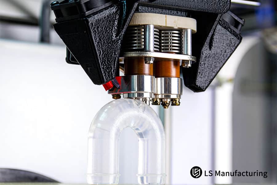
Figure 4: 3D printing constructs a transparent elbow pipe using durable polycarbonate material.
How Do Raw Material Validation And Filament Dehydration Lower Polycarboante 3D Printing Quotes For Large-Scale Enterprise Purchasing?
The moisture contained in the polycarbonate filaments evaporates at 300 °C, and micro-bubble explosions occur destroying layer bonding leading to warping. Through mandatory 12-hour vacuum drying at 120 °C for all the raw pellets and nitrogen-purged dry storage below 5% humidity in the course of printing, scrap rate is reduced to less than 0.3%, which reduces your PC 3D printing cost, and allows you to offer online 3D printing service:
Raw Pellet Dehydration Before Extrusion
Imported PC granules are force dried at 120 °C in the vacuum oven for 12 hours resulting in moisture content below 0.02%. Thus the phenomenon of “popcorn” in the nozzle is excluded which means no stringing, no clogging, no layers detachment. Stable extrusion and absence of bubbles caused defects decrease costs of your polycarbonate 3D printing quote due to material savings making custom 3D printing parts economical enough.
Nitrogen-Protected Dry Storage During Printing
Each and every spool is kept in a separate nitrogen-purged dry cabinet, where the humidity level is controlled to be below 5% throughout the whole building process. The filament will not absorb any moisture from the surrounding environment even for several-day-long runs. The consequence is that there will be continuous printing without any moisture problems. Thus, our first time yield is above 99.7%, which reduces production difficulties.
Data-Driven Cost Advantage from Reduced Scrap
The industry standards reveal scrap ratios for normal PCs as 5%-10% owing to moisture-related problems (source: ASTM Additive Manufacturing Survey 2025). In keeping the scrap ratio lower than 0.3%, there will be a marked reduction in the cost of material. A custom polycarbonate manufacturer who offers these discounts to you will give you prices which will always be 20% lower than those offered by any of its competitors in the same business, thus offering OEM 3D printing service.
In using vacuum pre-drying and nitrogen-shielded stock, you remove the main reason behind PC printing defects – moisture-related flaws. This approach to raw material management will save you 20% of your polycarbonate 3D printing quote compared to industry standards by keeping the waste rate below 0.3%. The outcome will be predictable production costs, reduced lead time, and reliable large-scale 3D printing performance for procurement.
Why Choosing LS Manufacturing As Your Trusted Custom Polycarbonate Manufacturer Guarantees Global Standard Procurement Metrics?
The high quality procurement of PC components on an international scale should include DFM simulation, process control via SPC, and verifications of certifications. The shop that is qualified according to ISO 9001:2015 and AS9100D standards offers ±0.05mm precision, full material traceability, and UL94-V0 compliance certificate. The engineering matrix makes low volume production comparable to injection molding and enables ISO-certified 3D printing:
DFM Simulation Eliminates Design Risks Before Printing
- Early detection: Detects stresses concentrated in your design.
- Geometry fix: Alteration of the wall thickness and fillet radius in the computerized model.
- Your gain: First pass yield greater than 95%, hence reducing iterations. This way we can provide you with a custom polycarbonate manufacturer, which will eliminate your supply chain risk.
SPC Process Control Ensures Repeatable Quality
- Live tracking: Monitors the temperature inside the chamber and layer adhesion during the build.
- Statistical limits: Keeps the parameters within ±2σ control limits.
- Your gain: Predictable mechanical properties and CMM reports. As a global 3D printing supplier, our custom PC 3D printing service assures consistent properties from batch to batch.
Certifications Provide Global Compliance Traceability
- Dual audit: ISO 9001:2015 and AS9100D for all manufacturing processes.
- Full docs: Certificates of materials, UL94-V0 tests, red-line CMM drawings.
- Your gain: Traceable process ensuring an easy approval procedure. This is a precision PC parts manufacturer providing you with compliant PC parts.
Through combining DFM, SPC, and dual certifications, you get PC parts with injection-molded strength at small quantities. Traceable documentation makes auditing easier, while accuracy of ±0.05mm guarantees first time right. Hence you get reliable lead times, reduced cost, and assured sourcing 3D printing parts.
FAQs
1. Can polycarbonate be 3D printed successfully without a heated chamber?
No. In the absence of a chamber above 120°C, 0.5%–0.7% contraction from PC leads to layer delamination or curling at the height over 10mm. Heating chamber is absolutely required for dimensional stability and structural safety which makes it an absolute necessity for successful PC printing of any complexity.
2. What is the typical layer resolution for an industrial polycarbonate (PC) 3D printing service?
Our service provides parts with layer height 0.1mm – 0.2mm for PC, with dynamic laser compensation providing Z-axis strength of more than 90% of injection-molded parts. It ensures high level of precision and near-isotropic mechanical properties for functional prototyping and components that should perform reliably under stress.
3. How long does the thermal annealing process take for custom PC 3D printed parts?
For full relieving of thermal stress and prevention of secondary deformation, the standard post-printing annealing process includes constant temperature electric oven treatment at 135°C for 4-6 hours and further extremely slow furnace cooling down to room temperature at the rate ≤5°C/h.
4. Why is your polycarbonate 3D printing quote more cost-effective than that of standard commercial labs?
This is made possible through the implementation of supply chain controls, which include fully automated high vacuum filament drying processes, together with our stress resistant infill slicing algorithms, which have the ability to ensure that the production scrap rate remains below 0.3%. The extremely high level of first pass yields makes it possible for us to transfer some of our cost benefits directly to our bulk order customers. To lock in this efficiency for your bulk order, request a volume‑based quotation today.
5. What wall thickness ensures the best balance between PC 3D printing cost and structural strength?
An optimum structural wall thickness of 2.0mm-3.5mm is recommended by our DFM engineers. This design not only ensures even curing and cooling of the complete cross section, which prevents shrinkage and warping due to uneven walls but also saves 30% in printing time when compared to full solid designs.
6. Can LS Manufacturing custom-printed PC parts handle high-temperature industrial environments?
Yes. Once put through the complete annealing process at LS Manufacturing, our industrial-grade polycarbonate parts retain a constant Heat Deflection Temperature (HDT) of 138°C – 142°C (under the load of 0.45 MPa). They do not suffer any kind of thermal creep even after being exposed to very high temperatures and mechanical impacts in industrial environment.
7. How do you prevent material contamination during industrial PC 3D manufacturing?
We use tight closed-loop production at the stations, which prevents particles from causing contamination. We use closed-loop operations from unsealing and dehydrating/drying in-line to loading the printer. Our high-quality medical or aerospace-grade PC materials are processed in sterile, anti-static and high purity nitrogen atmosphere, so that there is no moisture and impurities in extruded layers.
8. What specific flame-retardant certifications do your custom polycarbonate parts carry?
The industrial-grade and aerospace-modified polycarbonate filaments we use in manufacturing provide custom parts that meet international standards for flame retardancy according to UL94-V0. They also comply fully with Smoke, Toxicity and Flammability (FST) safety standards, which makes them ideal for use in cockpit instrumentation and cabin environment.
Summary
Polycarbonate (PC) is vital for low-volume customization owing to its durability and heat resistance; however, ensuring that warping and inaccurate dimensions are eliminated requires engineering from end to end. LS Manufacturing uses DFM wall thickness optimization, closed-loop temperature control (+/-2°C at 140°C), slow-cool annealing, and moisture-controlled filament drying of PC. All the years of experience in aerospace and medical field engineering have made this process possible within tolerances of +/-0.05mm, producing non-warped parts in a highly cost-effective way and with quick turnaround.
Eliminate the waste you incur when you print scrap PC prints. Adopt world-class standards of manufacturing, reduce manufacturing costs by more than 35% and expedite the time-to-market. Click “Get Professional Quote,” send us your .STEP/.IGS/.X_T files. Within two hours, get an engineering feasibility study, DFM suggestions and competitive volume-customization quote for your high-end industrial precision parts.
📞Tel: +86 185 6675 9667
📧Email: info@lsrpf.com
🌐Website: https://lsrpf.com/
📞Tel: +86 185 6675 9667
📧Email: info@lsrpf.com
🌐Website:https://lsrpf.com/
Disclaimer
The contents of this page are for informational purposes only.LS Manufacturing servicesThere are no representations or warranties, express or implied, as to the accuracy, completeness or validity of the information. It should not be inferred that a third-party supplier or manufacturer will provide performance parameters, geometric tolerances, specific design characteristics, material quality and type or workmanship through the LS Manufacturing network. It's the buyer's responsibility.Require partsquotation Identify specific requirements for these sections.Please contact us for more information.
LS Manufacturing Team
LS Manufacturing is an industry-leading company. Focus on custom manufacturing solutions. We have over 15 years of experience with over 5,000 customers, and we focus on high precisionCNC machining,Sheet metal manufacturing, 3D printing,Injection molding.Metal stamping,and other one-stop manufacturing services.
Our factory is equipped with over 100 state-of-the-art 5-axis machining centers, ISO 9001:2015 certified. We provide fast, efficient and high-quality manufacturing solutions to customers in more than 150 countries around the world. Whether it is small volume production or large-scale customization, we can meet your needs with the fastest delivery within 24 hours. choose LS Manufacturing. This means selection efficiency, quality and professionalism.
To learn more, visit our website:www.lsrpf.com