 English



TL;DR: The sheet metal K-factor is a dimensionless constant used to determine the location of neutral axes when bending the metal used in the automotive industry. Using deformation physics of sheet metal, it provides calibrated bend allowance calculations to maintain precision tolerances of ±0.05 mm.
In the case of junior purchasing professionals and engineering trainees, creating flat blank patterns for automotive parts is likely to create unforeseen dimensional inaccuracies as well as tear formations. In reality, determining precise baselines for sheet metal bending enables the correct digital 3D sheets to correspond to press-brake metal displacement without constant adjustments in tooling. This easy guide highlights the basics of neutral-layer mechanics, together with empirical automotive bending rules.
Key Takeaways
- The K-factor is the ratio of the neutral axis movement: it measures the displacement of the strain-neutral plane of the sheet when it bends, and for typical car material, it usually converges from 0.25 to 0.50.
- The minimum bend radius is an anti-tear line: the resulting inner radius will usually be limited to 1.0T-3.0T (T= thickness of the sheet) so that the outer fibers do not exceed their critical elongation point.
- Accuracy is ensured with calibration, not estimation: by compensating for true material displacement, forming dimensional tolerance is consistently held within ±0.05 mm precision.
- Bending process dictates the form: air bending and bottom bending have completely different characteristics regarding die interaction, therefore the springback and Y-factor correction coefficient change.
About the Author of This Guide
This guide is authored by Gloria, who works as a rapid prototyping and agile manufacturing expert at LS Manufacturing. With over 15 years of experience in precision engineering and stamping formability, Gloria specializes in understanding the mechanics of material plastic flow in order to turn it into deterministic design rules via early Design for Manufacturability (DFM). All geometry equations and forming process constraints in this article have been verified by the LS Manufacturing Stamping Process Technical Committee. Read more about Gloria's engineering knowledge from her LinkedIn page:Follow Gloria's Engineering Insights on LinkedIn
What Is Sheet Metal K Factor in Automotive Press Forming?
The sheet metal K-factor is the unitless fraction of the location of the neutral axis over the original sheet thickness in the course of bending.
- Strain dynamics: As explained in the chapter on bending mechanics in the Machinery’s Handbook (30th edition, Chapter 25), the outer surface of the sheet is elongated and thinned out, whereas the inner surface is shortened and thickened.
- Neutral plane shift: This movement displaces the neutral plane (zero strain) from the midpoint of the thickness to the inner part of the curve.
- Typical values: The actual measurement falls between 0.25 and 0.50.
- Application: Mastering the precise sheet metal K-factor is essential for calculating accurate flat blank length to achieve reliable ±0.05 mm forming tolerances.
Physical Analogy and Influencing Factors
For illustration, one can think of the neutral axis as of the railroads' railroad bed running in the middle of the sheet thickness:
- Prior to bending, it lies at 0.50T.
- With the press brake closing, the arc’s outer side has to move a greater distance than its inner side, thus the railroad bed moves to the inner side of the curve.
Key takeaway: K is not an inherent property of the material but rather a result of the interaction of material, tooling, and bending geometry.
The Related Y-Factor: Understanding k factor vs y factor
Another closely-related idea is the Y-factor, described by the equation:
Y = K × (π / 2) ≈ K × 1.571
- Role: While K indicates the location of the neutral axis, Y is incorporated into both the bend allowance and the bend deduction formulas for sheet metal flat patterns.
- Cross-check standard: The Y-factor value of 0.50 for a typical air bend of 90 degrees in mild steel corresponds to K = 0.318, an important cross-check if the vendor gives you a bend table with no explanation of how it was derived.
References:Machinery's Handbook, 30th Edition, Chapter 25 (mechanics of bending).
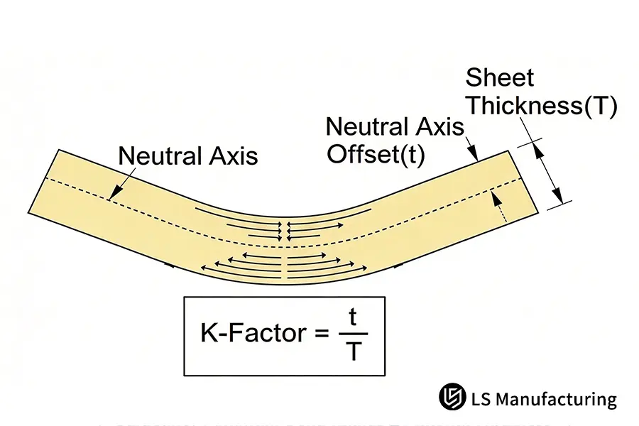
Figure 1: Cross-sectional mechanics of neutral axis displacement and the formula for calculating sheet metal K-factor (K = t / T).
What Is the Minimum Bend Radius for Structural Brackets?
The minimum bend radius is the least inside radius of a structural bend that can be made before the elongation of the outer surface exceeds the material's critical tear limit. As per the ASM International standard on metal-forming failure, any punch nose radius smaller than the minimum bend radius causes the elongation of the outer fibre to exceed the elongation limit and causes intergranular micro tears. In cold-rolled mild steel stampings and structural aluminium stampings, the engineering safe inside bend radius is usually 1.0T to 3.0T of the thickness of the sheet metal which keeps the fatigue critical section roughness of the part below Ra 1.6 μm.
The rule of thumb for this is simple: the thinner the sheet metal, the smaller the radius, but the ratio of the radius to thickness remains the same. A 2.0mm sheet metal bent at 1.0T radius would need 2.0mm inner radius, a 3.0mm sheet metal bent at 1.0T would need 3.0mm radius. The only thing that varies between materials is the lower limit – a ductile metal would allow 1.0T, while a precipitation hardened metal would require 2.5T or 3.0T.
The other aspect of grain structure is grain direction, which is far and away the most common cause of part passing in one blank lot but failing in another due to cracking.
Metal Bending Sensitivity to Grain Direction
- Bend line aligned with rolling direction (0° grain angle): poor transverse ductility, so increase inner radius greater than 2.5T.
- Bend line perpendicular to rolling direction (90° grain angle): optimal ductility allows small inner radius of 1.0T.
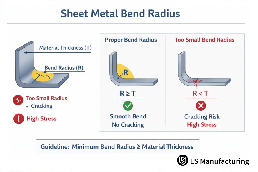
Figure 2: Safe minimum bend radius rules (R≥T) to eliminate stress concentration and outer fiber fracture.
In summary, grain orientation determines if your bend works with or against the grain. If the bend line is parallel to grain orientation, the bend requests elongation in the short direction of rolled fibres. This is the reason a piece of wood will crack along the grain line rather than against it. Grain alignment at 90° should therefore not be considered optional, but necessary for small-radius bending.
The following table compares four key automotive sheet metals across their formability limits, typical K-factor ranges, and suitability for air bending:
|
Material type and grade |
Recommended minimum bend radius (R) |
Typical K-factor range |
Key plastic-deformation feature |
Typical automotive structural application |
|
Cold-rolled mild steel (SPCC / DC01) |
1.0T |
0.38–0.44 |
Excellent ductility, low springback, stable plastic flow |
Chassis locating brackets, instrument-panel mounting frames |
|
Aluminium (6061-T6) |
2.5T–3.0T |
0.40–0.46 |
High yield strength, limited elongation, highly sensitive to stress concentration on the outer surface |
Battery-tray reinforcing beams, lightweight crash-beam members |
|
Deep-drawing aluminium (5052-H32) |
1.0T–1.5T |
0.35–0.42 |
Good ductility with moderate work-hardening, natural radius transition |
Battery-module separator housings, cooling-plate brackets |
|
High-strength low-alloy steel (HSLA 350) |
2.0T–2.5T |
0.42–0.48 |
Significant elastic recovery, marked neutral-axis shift, requires springback-angle calculation |
Suspension-control-arm mounting seats, B-pillar energy-absorbing liners |
To summarize, mild steel with high ductility can allow the smallest bend radius while alloys like 6061-T6 with high strength have to accommodate a large safety radius in order to prevent micro-tensile fractures. This table demonstrates why one K-factor is insufficient because different materials move the neutral plane by various extents and therefore should have their own flat pattern.
References: ASM International forming failure guidelines; ISO 2768-m general tolerances for metals; LS Manufacturing process engineering database.
How Do Engineers Calculate K-Factor in Sheet Metal DFM?
The sheet metal K-factor is calculated through empirical back-calculation using physical bend test coupons rather than generic software tables. Under ISO 2768-m standards, the bend allowance equation is defined as BA = π × (R + K × T) × (A/180), where R is the inside radius, T is sheet thickness, and A is bend angle. By measuring the post-forming developed flange length on a coordinate measuring machine (CMM), engineers solve for K = ((180×BA)/(π×A)-R)/T. For automotive cold-rolled steel and aluminum alloys, typical validated values converge between 0.30 and 0.46 depending on punch tip geometry and V-die opening width.
Formula also provides explanation as to why the value of K is tooling-specific. For fixed T and A, an increase in inside radius R increases the distance between neutral axis and mid-thickness plane moving the value of K closer to 0.50; the decrease in inside radius brings K value closer to 0.25. Mathematically speaking, K cannot have the same value for the identical bending of the part in press brake and in stamping dies. Why? Because tool geometry is embedded into K.
The reference k factor sheet metal chart below provides calibrated baseline values for practical shop-floor use, serving as initial starting points before batch validation:
Empirical K-factor starting values for different materials and modes of bending.
|
Material |
Bend mode |
Starting K |
Y-factor (K × π/2) |
When to recalculate |
|
SPCC / DC01 (1.0–3.0 mm) |
Air bend 90° |
0.40 |
0.63 |
New die opening or material batch |
|
6061-T6 (2.0–4.0 mm) |
Air bend 90° |
0.42 |
0.66 |
Every new lot — grain and temper vary |
|
5052-H32 (1.5–3.0 mm) |
Air bend 90° |
0.37 |
0.58 |
After a die change |
|
HSLA 350 (2.0–4.0 mm) |
Bottom bend 90° |
0.44 |
0.69 |
After any springback-angle adjustment |
This is a point of reference only. A different material hardness level, V shape, or batch of material with a different yield strength will change K by several percentage points, and this change could bring the critical dimension out of tolerance range.
References: ISO 2768-m, general tolerances for metals; bend development calculation method based on Machinery's Handbook.
Empiric Three-Step Procedure of Validation of Bend Chart Developed in Excel
Step 1. Take a reference rectangular sample and measure the thickness T using a digital micrometer.
Step 2. Apply a 90° reference bend and measure the profile and outer edge of the bend arc using a Mitutoyo roughness/contour measuring system.
Step 3. Determine the difference in total bend development and enter it into the bend development chart Excel spreadsheet.
How Does Air Bending Differ Mechanically from Bottom Bending?
1. Mechanical Constraints and Springback
The difference between air bending and bottom bending lies in mechanical constraint of the material with the lower die and the level of plastic hardening of the sheet:
- Air bending: The sheet contacts the punch tip and two shoulders of the lower die; therefore, the formed inside radius depends on the width of V-opening and the process involves considerable springback.
- Bottom bending: The punch pushes the material into the die groove and thus causes local hardening and reduces the springback.
- Significance: The physical difference in contact becomes the basis of the correction border of K-factor and Y-factor during the process of 3D development.
2. Quantitative Geometric Differences
The geometry within the bend provides the quantitative difference:
- Air bending: The radius is one sixth of the V-opening width, which means that if the width is 12 mm, then the radius will be equal to 2.0 mm.
- Bottom bending: The formed radius depends on the nose of the punch, which can vary from 0.6T to 0.8T, and the material is hardened within this radius.
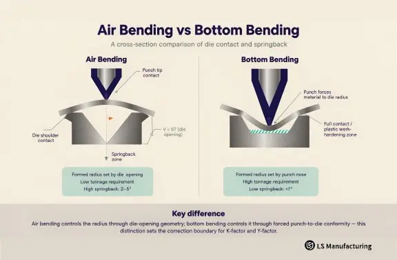
Figure 3: Tool-to-sheet interaction and bend angle clearance: (a) Air bending acute over-bend stroke; (b) Bottom bending full groove conformity.
3. Impact of Y-Factor and Cumulative Errors
Y-factor serves as the connection between the two approaches, given that Y = K * (pi / 2):
- Flat length variance: Using the same bending angle to determine the flat length using a K value of 0.44 for bottom bending and 0.40 for air bending results in a slight difference in the flat length of about 0.12 mm on a 60 mm leg.
- Tolerance stack-up: In a bracket that has been bent six times, the differences add up to produce a piece that will not fit in its assembly.
Key takeaway: One should not take the bend tables of a bottom-bent piece and apply them to an air-bent piece even when the material is the same.
When Do Automotive Sheet Metal Bending Rules Prevent Scrap?
When standardized automotive sheet metal bending rules are applied during early DFM design—defining hole-to-edge distance, flange height, and bend relief—scrap can be eliminated before the first tool tryout.
1. Bend Relief Guidelines: Preventing Uncontrolled Tearing
Engineer’s Note on Bend Relief: In automotive bracket and stiffener design, a bend relief is a rectangular or tear notch placed at the intersection of a bend line and an adjacent flat edge. Without an adequate relief, transverse tensile stress causes uncontrolled tearing into the adjoining material. To prevent cracking, the relief depth must exceed the inside bend radius plus material thickness (Depth ≥ R + T), while the relief width should equal at least sheet thickness (Width ≥ T). Incorporating this simple geometry during initial blank design eliminates one of the most common causes of automotive stamping scrap.
2. Feature Proximity and the 2T + R Rule
Contrary to common belief, the most frequent cause for scrap is not having an inadequate radius but putting the geometry in proximity to the bend. Since the part has been punched prior to being bent, the hole will be located within the zone where material is going to be stretched or compressed depending on the location of the punch relative to the bend tangent line.
Consequently, the 2T + R guideline is a matter of designing and not of quality control since nothing will put the hole back into position once it has been punched too close to the bend. According to LS Manufacturing Engineering guidelines, there should be at least a 2T + R distance between the punched edge and the tangent of the bend.
3. Datum Hole Stability Across Multiple Bends
On a complex bracket with multiple bends, locking the inside radius within a conventional tolerance of ±0.05 mm reduces the geometric shift of the assembly datum holes in the batch by more than 70%.
How to Prevent Sheet Metal Bending Cracks in Production?
Bend cracks can be prevented through control of tensile strain in the outer wall and reduction in notch sensitivity in the edge. The primary sheet metal bending cracks causes include forming below the critical minimum radius, aligning bend lines parallel to the coil rolling direction, and leaving micro-notches along sheared edges without deburring. Increasing the inside bend radius above 1.5T, keeping the blank layout in a position 45°–90° from the rolling direction, and achieving a surface roughness of Ra 1.6 µm in the sheared edge will ensure no growth of outer grain boundary micro-cracks under cyclic loading.
This therefore means that crack prevention is a series of three individual controls and not just one single control setting. Increase in the bend radius will not be able to rectify bad grain orientation, while proper grain orientation will not be able to salvage a notched edge.
During production, they are all checked at once; that is why a crack, which shows up suddenly, tends to be a problem with just one of them: a new material batch, a damaged punch, or a missing deburring stage.
The following checklist consists of steps, which should be taken initially upon appearance of cracks in production process. Intentionally, the steps go from the least to the most expensive in terms of making changes.
Remedial Action for Surface Micro-cracks
1. Perform a vibratory finish treatment of the laser cut or blanked edge in order to eliminate the hard micro-slag layer and burr on the edge.
2. Choose a die having wider V-opening in order to lower the instantaneous strain rate on the outer wall of the bend.
3. In cases when it is possible, use the technique of bend-then-machining in order to make the holes and slots after the part has been formed and not before.
4. For high-strength tempering materials, which show cracks in the as-received condition, use T4 or annealed tempering for bending and then restore the required hardness via artificial aging process after bending.
Observe the trade-off here: heat treatment introduces an additional process and an associated delay in lead time, but eliminates the problem of cracks completely, whereas it merely reduces the chance of cracks. In the case of critical safety parts, it normally turns out to be the more economical choice when one accounts for scrap and rework, but the decision should be made at the design stage, not the shop floor.
References: General Requirements ASTM A480 for Flat-Rolled Stainless Steel Products; Geometric Dimensioning & Tolerancing ISO 2768-m; Forming ASM Handbook Vol. 16.
How Bending Rules Work in Practice: An Automotive Battery Bracket Example from LS Manufacturing
Core Takeaway
A larger bend radius alone does not fix cracking; radius, grain orientation, and developed length are interconnected factors in the same equation, and adjusting one without recalculating the others simply shifts manufacturing defects elsewhere on the part.
1. Initial Challenges and Root Causes
During the initial design phase of a 2.5 mm 6061-T6 aluminum reinforcement bracket for a new-energy vehicle battery tray, two critical processing failures emerged:
- Surface and Feature Defects: Micro-cracks formed along the external bend face, accompanied by out-of-tolerance axial displacement of the locating holes.
- Flawed Initial Parameters: The original flat pattern ignored material rolling direction, applied a generic tolerance of ±0.1 mm, and specified an inside bend radius of 1.0T (2.5 mm)—a value well below the allowable threshold for structural aluminum alloys.
2. Engineering Adjustments and Process Optimization
The LS Manufacturing application-engineering team resolved the defects by systematically recalibrating the material and tooling parameters:
- Empirical K-Factor Testing: Conducted 90° bend testing on the specific material batch using custom dies to measure an exact K-factor of 0.42.
- Radius Correction: Leveraged springback modeling and fracture mechanics to increase the load-carrying inside bend radius from 1.0T (2.5 mm) to an industry-standard 2.5T (6.25 mm).
- Grain Alignment and Compensation: Re-oriented the flat pattern so the primary bend line ran perpendicular to the rolling direction, recalculating bend-unload compensation according to the updated developed length.
3. Production Results and Quantified Impact
Implementing these coordinated adjustments yielded substantial improvements in quality, lead time, and cost:
- Dimensional Precision: Maintained the bend edge geometry within a tight tolerance of ±0.05 mm across the batch.
- Defect Reduction: Completely eliminated surface micro-cracking and cut the overall scrap/defect rate from 16% to 4%.
- Efficiency Gains: Accelerated prototype development by 14% and decreased total manufacturing and development expenses by 9%.
Reference:Automotive bracket bending project #AUTO-2026-083, drawn from the LS Manufacturing 2025–2026 measured data set (sample size >800 parts).
FAQs
Below are the responses, presented in definition format first, followed by the principle behind the response. All numerical values are presented in their starting range format, not universally applicable specifications.
What is the range for normal K-factor in automobile steels and aluminum?
Normal K-factors for common cold rolled mild steels and aluminum sheet materials range between 0.25 and 0.50. This is directly dependent on the yield strength, work-hardening exponent, and lower die opening geometry. In the LS Manufacturing standard processing database, it is calculated using bend specimens as opposed to a generic table.
What effect does the direction of the material's grains have on minimum bend radius?
Bending rolls cause the material grains to lie parallel to each other. In the event that the bending axis lies parallel to the rolling direction, there will be a reduction in transverse ductility and the outer wall would be more likely to crack; LS Manufacturing therefore suggests that the layout angle be either 90° or 45° in relation to the rolling direction.
Does bigger radius always mean better clearance in auto assembly?
No, because very small radius leads to great stress concentration, causing tearing of the outer fibers, and fatigue strength drops due to vibration. LS Manufacturing experts normally advise to use a smooth inside radius not less than 1.0T where possible according to the assembly requirements.
What are the reasons for dimensional tolerance when bending the same sheet metal parts?
They include small changes in thickness, yield strength, and springback angle variability in air bending. At LS Manufacturing, using the accuracy control of ±0.05 mm and installing a dynamic thickness adjustment mechanism on the lower die maintains dimensional tolerance.
Summary of Precision Sheet Metal Forming Mechanics
Knowing the rules of neutral axis displacement controlled by the K-factor and the scientific determination of minimum bend radius becomes the basis for avoiding interference in assembly and fatigue cracking in automotive sheet metal components. Design geometry derived from calculations in material mechanics minimizes tryout iterations and ensures the design of the part from digital to highly precise physical one.
The next stage involves application of the rules to a particular drawing. The pages dedicated to the cluster below use the same approach in comparing and deciding on such aspects as ranking of materials, tolerance usage, and differences in prototype versus volume production of the component.
Related Engineering Guides & Next Reading Steps:
Material Comparison: Aluminum 6061-T6 vs. 5052: Which is Best for Your Sheet Metal Fabrication Project?
Process Comparison: Air Bending vs. Bottom Bending: Dimensional Accuracy and Tooling Wear Compared

Glossary of Forming Terms
The short definitions below are the ones used throughout this guide, written for a reader who is seeing the terms for the first time.
|
Term |
Definition used in this article |
Why it matters |
|
K factor |
Dimensionless ratio of the neutral-axis location to sheet thickness T |
Determines the flat blank length for a given bend |
|
Y-factor |
K × (π / 2); enters the bend allowance and bend deduction terms |
Connects material shift to flat-pattern arithmetic |
|
Neutral axis |
The layer through the thickness where strain is zero during a bend |
Its shift is the physical origin of K |
|
Minimum bend radius |
Smallest safe inside radius before the outer surface tears |
Sets the anti-cracking limit for each material |
|
Bend allowance (BA) |
Extra length added to the flat pattern for a bend |
Together with bend deduction it defines the blank |
|
Bend deduction |
Length removed from the sum of two legs to obtain the flat length |
What is measured on a CMM to back-calculate K |
|
Air bending |
Sheet contacts the punch tip and two die shoulders only |
Lower tonnage, higher springback, radius set by V-opening |
|
Bottom bending |
Punch forces the sheet into full contact with the die groove |
Higher tonnage, lower springback, radius set by punch nose |
|
Bend relief |
Notch cut where a bend line meets a flange or feature |
Prevents uncontrolled tearing at the intersection |
|
Springback |
Elastic recovery of the bend angle after the punch retracts |
Must be compensated in the punch angle and K value |
References and Technical Sources
- Machinery's Handbook, 30th Edition, Chapter 25 – bending mechanics, bend development equations.
- ASM Handbook Volume 16: Forming – forming mode contact mechanics, spring back.
- ASM International – metal forming failures (minimum bend radius, ductility).
- ISO 2768-m – general tolerances of linear and angular dimensions in metal parts.
- ASTM A480 – general requirements for flat rolled stainless and heat resisting steel plate, sheet and strip.
- LS Manufacturing Stamping Process Technical Committee – internal process review of the article.
- Measured database from LS Manufacturing, project number AUTO-2026-083, sample size >800 parts, 2025-2026.

