 English



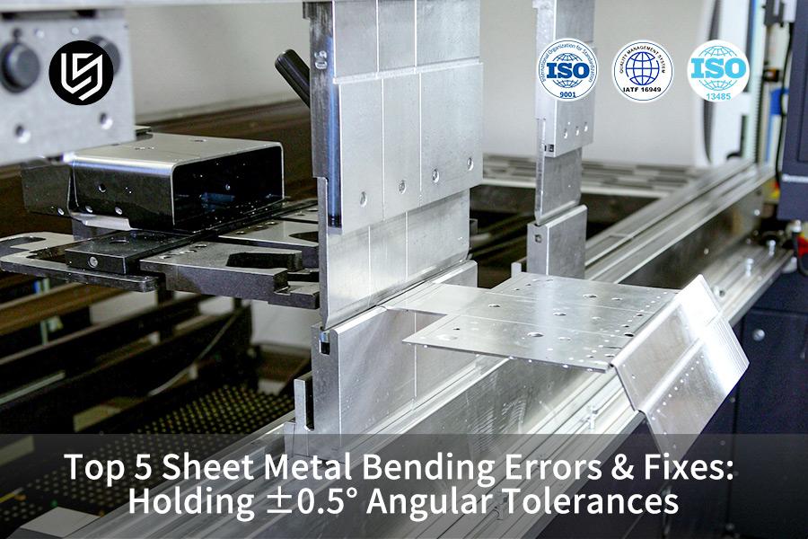
Sheet metal bending errors are angle deviations beyond ±1.0° that jam assemblies at welding stations; a laser closed-loop bending process holds them within ±0.5°.
DFM reviews in 2 hours reduce defect rates to 2.1%, ending reaming for one-pass fit. Data Source: LS Manufacturing 2025–2026 log (>1,200).
Key Takeaways (Core Technologies and Business Principles)
Tolerance Leap Principle: Dynamic laser angle tracking obviates trial bends by hand. Laser angle tracking ensures no batch variation in yield strength. Closed-loop tolerance correction holds each bend within an accurate angular band. Assembly teams do not shim parts at welding fixtures.
Geometric Breakage Prevention Principle: Required distance from holes to bend determines clearance from hole edges to bend tangents. Hole edges do not enter outer plastic deformation region. Required clearance prevents stretching of edges and flange breakage. Assembly teams install pins without reaming.
Efficiency Closed-Loop Principle: Grain-aligned nesting configurations align crystal structure prior to laser cutting. Verification programs for die contours detect wear early. Cost of manufacturing each part is lower because of consistent first article. Tightened delivery schedules result in fewer iterations. Hardware procurement plans synchronize installation dates with shipped dates.
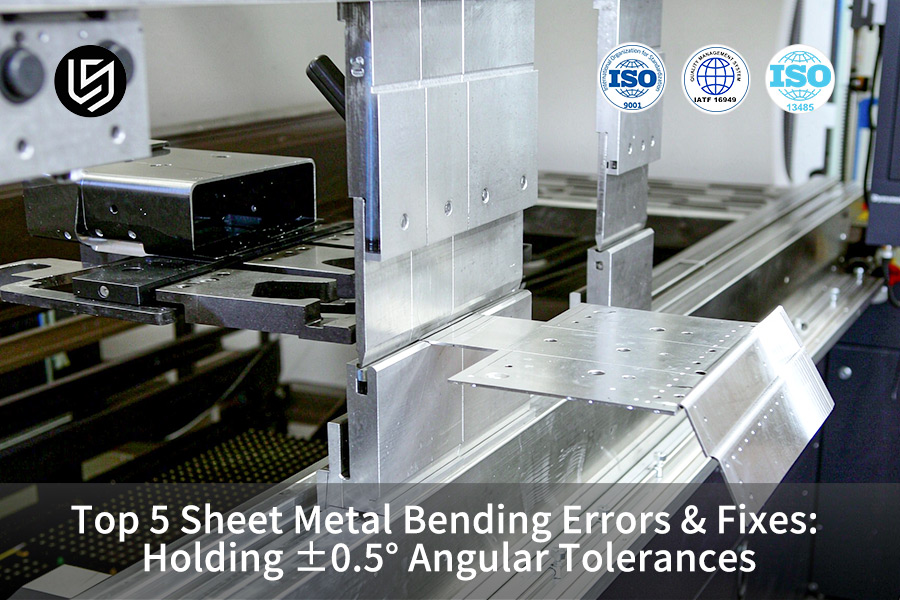
How Does Material Springback Cause Sheet Metal Bending Errors?
Material springback is the elastic strain release that shifts bend angles by up to 1.5° after cold press-brake bending. Elastic strain release results in geometrical angle variation due to batch yield variation of cold-rolled steel and stainless steel. Angular drift leads to sheet metal bending errors beyond ISO 2768-1:1989 assembly tolerance for general angular tolerances.
Air Bending vs Bottoming: Springback and Tonnage
Air bending technique results in high springback drift on stainless steel grades. Bottoming and coining techniques decrease elastic recovery through higher press brake tonnage. Air bending and bottoming techniques require compensation in order to keep batch angles constant. Buyer receives a custom metal bending prototype with correct angles prior to mass production.
| Bending Method | Springback Drift | Final Batch Angle | Tonnage Demand |
| Air Bending | High | Controlled | Baseline |
| Bottoming / Coining | Minimal | Controlled | Higher |
Air bending reduces tooling cost, whereas dynamic ram compensation ensures the angle window that is necessary for a precision sheet metal bending service.
Dynamic ram-depth micro-adjustment ensures that press brake springback is prevented via correction of the elastic recovery in real-time.
A sheet metal bending quote with angle compensation makes sure your budget is secure. Simply put: elastic recovery is no longer causing problems in your assembly fit. Dynamic compensation keeps your batch angles within ±0.5° during each production cycle. CMM (Coordinate Measuring Machine) inspection verifies the angle window before shipping.
Data source: LS Manufacturing 2025–2026 automated DFM 3D/2D drawing parsing log (sample size >1,200).

Why Does Bed Deflection Break Sheet Metal Bending Angle Tolerance?
Bed deflection is elastic arching of a press brake bed under high tonnage, resulting in a formation of a boat-shaped angle deviation measuring 91.5° at mid-span and 90° at both ends. With multi-axis CNC crowning (micron-level hydraulic compensation axis), it is possible to achieve one single force line throughout the entire length of the bed, maintaining angle accuracy up to ISO 2768-m. Center-heavy angles become non-existent when there is a pre-load on the lower bed.
How Elastic Arching Forms Boat-Shaped Angles
Bed arching increases with part length and press tonnage; thus, a longer part gets lower penetration of the die in the middle point. Lower center penetration results in opening up the bend to 91.5° in the middle, but both ends are at 90°, damaging the fit of a custom metal bending enclosure.
Linear grating scales (in-line optical rulers measuring ram depth on each stroke) reveal drift during production. Fixed shim stacks fail to monitor such drifts, as shim thickness remains constant, whereas bed arching changes by each coil load, resulting in sheet metal bending errors during welding.
Two-Step Sequence for Full-Length Angle Control
- Scan ram depth with optical rulers and send readings to compensation axis.
- Pre-load lower bed with opposite curve to negate elastic arching and keep sheet metal bending angle tolerance within ISO 2768-m along the flange.
Crowning applies to all long flanges beyond base tonnage level. Simply put: a compensated bed takes hand-straightening labor hours out of long bent panels.
What to Request Before Tooling Investment
Full-angle mapping at center and both ends should be part of any custom sheet metal fabrication quote you consider. Without angle maps, boat-shaped drift stays hidden until assembly. Competent metal bending parts supplier delivers that data prior to tooling spend.
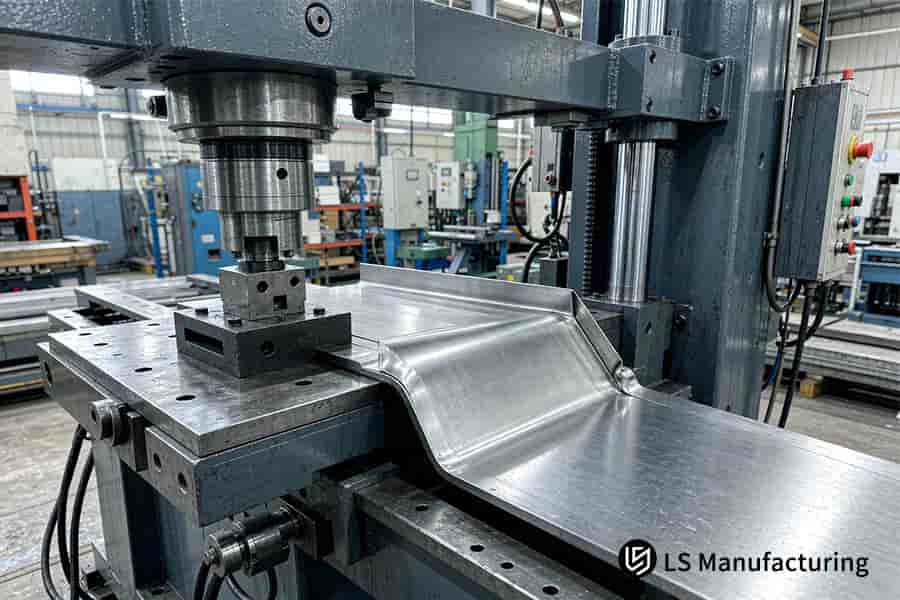
Figure 1: CMM angle check on a bracket flange shows hole deformation held at ±0.35°.
When Does Tooling Wear Violate Precision Sheet Metal Bending Service?
Tool wear is characterized by progressive adhesive and abrasive metal removal from punch tip and V-opening shoulder edges. Shoulder spalling to 0.1 mm alters flow resistance balance and bends beyond ±0.5° bend angle tolerance. Deep-cryogenic hardened tooling with hardness of ≥60 HRC and surface finish of Ra 0.8 μm prevents spalling for any precision sheet metal bending service.
When Shoulder Spalling Reaches Your Angles
Adhesive wear (transfer of material from the shoulder of the die to the sheet) increases during stainless steel production runs. More grades of stainless steel increase shoulder wear, hence the frequency of mapping that dictates how much you risk scrap.
Profilometer (measures die profile with contact stylus) mapping every 40–80 hours helps identify spalling early; sheet metal bending services ensure your fit during assembly.
V-opening shoulder radius (shoulder radius of the die that guides sheet flow) controls bendability of the sheet. Normal planed dies lose their shoulder radius fast, hence planer grinding dies fail during long production runs. Sheet metal bending errors reach your welding jig first.
Choosing Die Specs Before You Commit
Die geometry callouts are to be included in a sheet metal DFM design guide verified in accordance with ASME Y14.5-2018 (geometric dimensioning and tolerancing).
- Hardening: deep cryo treatment (sub zero soaking) rather than regular planing on subsequent re-orders.
- Shoulder finishing: ground radius in lieu of milled radius for stable sheet flow.
- Inspection history: contour traces logged per shift, not after customer complaints.
Documented die specifications reduce quotation cycle times since quotations are based upon the agreed upon geometry. Put plainly: hardened ground dies turn an undetermined angle drift into a documented inspection cycle. Documented inspection cycles will maintain your sheet metal bending cost constant over repeat orders.
Data basis: tool hardening and wear-limit judgment follow ASME Y14.5 (geometric dimensioning and tolerancing) and die-condition inspection specifications.
Quick Reference Table For Bending Condition Tolerances And Defects
Bending parameter comparison lists control capability across standard job-shop, precision and coining grades. Quality performance data accompanies every control dimension below. Sheet metal bracket fabrication buyers gain one reference point for tolerance bands and scrap risk before tooling money moves.
| Control Dimension | Standard Job-Shop | Precision Grade | Coining Standard |
| Angular Tolerance Capability | ±1.0° | ±0.5° (laser angle measurement, standard) | ±0.2° (custom dedicated forming die) |
| Linear Position Dimensional Tolerance | ±0.02 mm | ±0.01 mm | ±0.005 mm |
| Hole-to-Bend Safety Distance | < 2.0T (severe hole pulling) | ≥ 2.5T + R or ≥ 4T | Stress-relief slot cutting (zero hole distortion) |
| Die Hardness and Maintenance | Baseline < 50 HRC / deformation without inspection | ≥ 60 HRC / 80 h periodic inspection | ≥ 62 HRC / digital contour correction per batch |
| Overall Unit Scrap Probability | 8%–25% (based on LS Manufacturing 2024–2025 incoming-job audit) | Stable convergence to 2.1% | ≤ 1.0% (high-tier process quota) |
Metal bending angular deviation ±0.5°, ram positioning repeatability ±0.005 mm tolerance, saving metal bending rapid prototyping purchasers the trouble of re-correcting.
Receive the Bending Parameter Calibration Checklist — a printable reference that maps material grade, thickness, and die condition to the correct K-factor, springback compensation value, and hole-to-bend safety distance for each flange type.
Why Does Sheet Metal Bending Hole Deformation Ruin Part Quality?
Hole deformation occurs where hole edges extend into the plastic deformation area and into the tension stress region. Shear stresses tear hole edges into oval or twisted forms when the hole-bend distance falls below the ≥ 2.5T + R spacing limit. Your pin holes will remain circular above the spacing limit.
Safe Distance by Sheet Thickness
Hole-to-bend clearance (distance between the edge of the hole and the tangent of the bend line) determines the survival of mounting holes through bending operations. Large thickness requires more clearance than small thickness. Spacing rules belong in metal bending enclosure design from the first sketch. Late spacing fixes force new tooling.
| Sheet Thickness (T) | Safe Hole-to-Bend Distance | Bore Shape Below Safe Distance |
| 1.0 mm | 2.5 mm + bend radius | Slight ovality |
| 2.0 mm | 5.0 mm + bend radius | Visible ovality |
| 3.0 mm | 7.5 mm + bend radius | Warping plus edge tearing |
Safe distance increases with thickness. Thicker mounting plates require larger safe distances from all bend tangents. Boreholes outside the safe distance range prevent sheet metal bending hole deformation. Pin-fit limits in ISO 286-1:2010 remain valid until final assembly.
Relief Slot Placement Before Tooling
A tight design makes it necessary to use relief slots rather than spacing them out further. Relief slots (narrow slots cut along the bend tangent lines) prevent tensile stresses from affecting the hole edges. Holes punched near bends fail faster than laser-cut holes. Location of relief slots should be part of a sheet metal DFM design guide reviewed prior to tooling investment.
Your custom metal bending parts ensure that the bores are round after the relief slots cut off the stress path. In other words, round holes make it possible for your line to insert pins without any reaming stops. First article inspection at a precision sheet metal bending service ensures proper bore spacing.
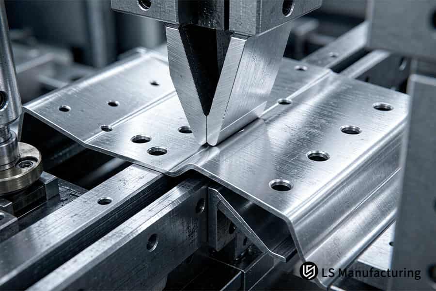
Figure 2: Metal bending sheet metal bending angle tolerance holds ±0.5°.
How Can Engineers Prevent Sheet Metal Cracking Along Bend Line?
Bend line crack is surface fracture that moves along grain boundaries with bend direction parallel to rolling grain direction (elongated crystals from mill rolling). Rotating blank by 90° will restore elongation reserve and stop cracking propagation. ISO 7438:2020 bend test (Metallic materials bend test) checks ductility of grain direction before tooling spending.
Grain Direction Rotation Sequence
Grain direction arrows need to be placed in sheet metal cracking along bend line nesting files prior to laser cutting.
- Rotate each blank by 90° such that bend lines intersect grain flow prior to cutting.
- Ensure 90° rotation guideline is embedded in your sheet metal DFM design guide before nesting program execution.
- Use 45° diagonal nesting approach when sheet size necessitates material compromise.
- Verify mill certification rolling direction information for all coils received.
Die Radius and Annealing for Hard Tempers
Full-hard cold-rolled tempers have low elongation reserve and are difficult to bend. Temperature-controlled local annealing restores ductility in the bend zone before forming.
Forming full-hard 301 stainless steel at a tight radius cracks the outer fibers; annealing restores ductility so the same tool can complete the bend. Die radius determines how to prevent press brake springback, and the grain direction controls cracking. Test bend samples cut from production coil lot reveal grain-direction cracking danger before selecting tooling. A coil that cracks in production costs far more than the test bend samples that would have flagged the risk first.
What Are The Fundamental Sheet Metal DFM Design Guide Rules?
Sheet metal bending DFM rules are engineering standards covering flat-pattern calculation, K-factor (neutral-layer position ratio) selection and bend-root relief reservation. Sharp inner radii below 1.0× material thickness drive most non-standard angle jump. ISO 2768-m linear and geometric datums anchor the verification matrix.
Minimum Inner Radius Decision
Minimum bend radius (minimum inner radius that a certain material can be formed without breakage) is the primary criterion. A minimum of 1.0×T inner radius is good for both cold-rolled steel and stainless steel materials. Metal bending review detects sharp radii call-outs prior to tooling investment.
- Elongation of material from mill certificates
- Grain direction indicated on the nesting layout
- Length of flange available for die contact
K-Factor and Flat-Pattern Decision
K-factor provides conversion of bends geometry to the flat blank length. Machinery's Handbook 31st Edition provides K-factor 0.33 – 0.50 for cold-rolled steel. Incorrect K-factors move holes after forming process.
Bend allowance (distance along the arc at the neutral axis) and straight flange sections define the length of the blank. A sheet metal DFM design guide determines the K-Factor prior to the nesting process. K-Factor must be included in your metal bending quote in order to match the quoted flat part dimensions with the delivered ones.
Relief At Multi-Flange Joints
Multi-flange corner (three or more flanges intersecting at one bend point) results in triaxial tension stresses. Relief notches larger than material thickness break the stress path. Sheet metal bending angle tolerance is limited to the drawing window in multi-flange enclosures.
Kerf relief notches relieve tensile stress in the bend root area; relief holes punched into the sheet do not, since punch burrs lift the flange above the die shoulder. Laser relief drawings are filed with the metal bending parts manufacturer's first article submission.
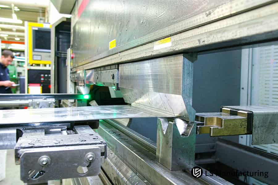
Figure 3: Metal bending how to prevent press brake springback uses ±0.01 mm laser.
Behind The Numbers: Practical Experience From LS Manufacturing Experts
Consult Gloria directly on LinkedIn — LS Manufacturing's senior sheet metal process engineer with 15+ years in precision engineering and rapid prototyping, and 1,000+ DFM programs. Gloria has led DFM improvements on more than 1,000 structural part programs. You can benefit from measured numbers over vendor assumptions.
In project #ROBOT-2026-842, trial bends warped as residual mill stress released at 350 °C. Annealing therefore ran before laser cutting. Blanks were arranged in a way to be perpendicular to rolling grain. ASME Y14.5-2018 dimensional drawing standards define checking distances from hole to bend. Each critical bend has been inspected according to ISO 2768-m conformance requirements.
Zeiss CMM (Coordinate Measuring Machine, 3D scanning verification) validated all angle log deliveries in each of 220 sample measurements. ISO 9001:2015 & AS9100D certified all CNC bending centers producing measurement data in accordance with press-brake criteria. Customers receive angle logs and 3D scanning documentation allowing incoming inspection teams to process docks without additional metrology queue times.
How Does Precision Sheet Metal Bending Service Ensure Accuracy?
A precision sheet metal bending service is an industrial control system driven by servo controlled closed loop, laser live angle gauging and segmented ground tooling. Laser non-contact gauging registers spring back drift constantly. Axes re-press at micron level in one cycle. Positioning repeatability ±0.01 mm defines modern bending cells compared to hand gauge trial bending.
Open-Loop Versus Laser Closed-Loop Control
Metal bending assembly service purchasers experience open-loop drift initially in welding jigs. Trial bending via manual method relies on hand gauges, first-part setup entails many test bends.
| Control Path | First-Part Setup | Scrap Behavior |
| Open-loop trial bending | Hand gauge, repeated test bends | Drifts per operator |
| Laser closed-loop control | One compensated stroke | Stable across mixed batches |
Since laser closed-loop control compensates in one stroke only, all sheet metal bending errors are contained in the cell itself. Manual trial bending cannot do that, as shim guesses vary for each setup.
Angle Verification With Coordinate Metrology
Zeiss CMM (coordinate measuring machine measuring finished bends) checks angles according to your drawing. Zeiss CMM calibration report (accuracy of measuring 0.0009 mm and spatial indication error MPEE) underpins every angle measurement. ISO 10360-2:2009 defines CMM acceptance criteria, which makes your angle report traceable and dispute-free at incoming inspection.
Holding Consistency Across Mixed Batches
Segmented modular ground dies (tooling divided into ground segments) ensure uniform pressure throughout the entire bending stroke. Servo crown adjusts compensation for every stroke, which guarantees sheet metal bending angle tolerance regardless of batches. Laser cut sheet metal blanks have uniform edges, minimizing setup differences at the brake.
For a buyer, mixed-batch orders get delivered within one repeatable angle range, not depending on the operator.
Data basis: precision indicators follow Zeiss CMM official calibration report (spatial error figure and 3D laser scanning mapping log).
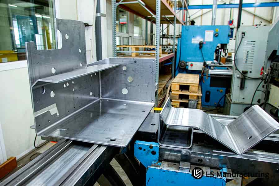
Figure 4: Metal bending sheet metal bending errors appear on ±0.5° bracket.
When Should You Request A Custom Sheet Metal Fabrication Quote?
A custom sheet metal fabrication quote is the purchasing gateway separating prototype validation from the engineering freeze stage, where process intervention still eliminates scrap factors. Quoting at drawing release identifies dead-edge hems, blind bend zones, and reverse deep interference prior to spending on tooling costs. Feasibility response is received within 2 hours of uploading 3D/2D drawings.
Signals Timing Your Quote Request
- Prototype validation approaching engineering freeze for brackets or metal bending enclosure manufacturer panels
- Bend features with dead-edge hems (closed flat bends) or blind bend areas
- Reverse deep interference (flange hitting tooling on return stroke)
- No grain direction indications on flat patterns
- Custom sheet metal fabrication quote after 3D/2D drawings uploaded
Reading Tolerance Grade Premium
ISO 2768-f (fine tolerance class according to ISO 2768-1:1989) costs more than ISO 2768-m on all bend tolerances. Coining-class angular tolerance bands need special forming tooling, hence cost per piece is raised by grade. Comparing quotes, buyers should consider grade based on fit, not draft style.
A sheet metal DFM design guide review makes grade per flange prior to quotations start. Simply put: fine class callouts on cosmetic flanges increase your cost and not the pin fit.
What Your RFQ Package Needs
- 3D and 2D drawing with grain direction arrows
- Grade, temper, and mill certification elongation
- Pin fit callout on hole to bend distance
- Quantity divided between prototype and production parts
A precision sheet metal bending service quotes tighter angle bands once that package arrives complete. Quick turn metal bending orders ship faster with full RFQ packages in hand.
LS Manufacturing Precision Sheet Metal Bending Service For Robotics Heavy-Payload Armature: Controlling ±0.5° Angular Deviations
Control over robotic armature angular deviations is a closed-loop bending process consisting of stress-relief annealing, grain-direction rotation, and laser relief slotting on 3.0 mm AL 5052-H32 blanks. Control over angular deviation within ±0.5° angle band through four continuous bends provides a proper concentricity of reducer base for heavy-payload robot wrists. All the frames are produced to ISO 2768 form tolerances.
Client Challenge
Six-axis heavy-lifting robot wrist arms employ AL 5052-H32 cold-rolled sheets in four sequential bends. Previous supplier was producing with a deviation of ±1.2° and with pin bore edges sheared by 0.35 mm. Scrap rate in an aluminum metal bending process was up to 14.8% and the order completion was overdue for 16 days.
LS Manufacturing Solution
First bending of raw coil material experienced springback due to the mill stress. Annealing process performed at 350 °C x 2 h was followed by laser cutting. In addition, nesting shifted to a 90° position against the rolling grain orientation and the laser relief slot 1.0 mm wide separated a pin bore 3.5 mm distant from the bend tangent line. Hardened and ground tools of hardness over 60 HRC with dual-side laser correction were used in all bending stations.
Delivered Results
Final measurements ±0.35°, with bore roundness of ±0.01 mm. Reject percentage stabilized at 2.1%. Unit cost dropped from $184 to $136, a 26.1% reduction. Lead time decreased from 17 to 10 days, a 37.5% cut. A supplier to a robotics equipment company has started mass production after completing precision metal bending services and full inspection. High-volume metal bending started after 5 million cycles of heavy-payload fatigue swings were performed.
The buyer's senior mechanical engineer commented: 'We stopped reaming pin holes entirely and cleared incoming inspection at the dock.' — Senior Mechanical Engineer, robotics equipment OEM (project #ROBOT-2026-842).
Data basis: LS Manufacturing Precision Manufacturing Center delivery log (project #ROBOT-2026-842, 220 measured sample sets).
Validate your hole-to-bend clearance against the 2.5T + R rule using our interactive distance calculator — input your material thickness and bend radius to receive a pass/fail verdict for each mounting hole, with automatic relief slot placement suggestions derived from the robotic armature case.

FAQs
1. How does LS Manufacturing ensure a tight angle tolerance within ±0.5° for stainless steel?
LS Manufacturing combines laser angle sensing with servo-pressure control for ≥ 60 HRC cryogenic tooling. Final stainless steel angles are controlled to within ±0.5° per stroke, and the incoming plate complies with ASTM A240. For incoming inspection groups, per-part angle data sheets let your incoming inspection team clear parts at the dock without a CMM backlog.
Data Source: LS Manufacturing 2025–2026 measured database.
2. What is the minimum recommended distance between an extruded hole and a bend line?
Holes closer than 2.5T + R to the bend line sit in the tensile stress zone and will tear or oval. Keep critical bores at ≥ 4T or add relief slots to protect pin fit. LS Manufacturing identifies such separations in the metal bending design review process and revises the callouts to ASME Y14.5-2018 prior to the tooling release. For assembly teams, this adjustment eliminates the need for reaming of pins into holes.
3. Can LS Manufacturing correct press brake deflection on parts longer than 2000 mm?
Bending of bed under press tonnage leads to lack of penetration of 2 000 mm pieces throughout the center of the piece. LS Manufacturing utilizes multi-axis CNC crowning axis which applies load on bed in every stroke and balances penetration according to ISO 2768-1:1989 general tolerances. In case of project #ROBOT-2026-842 OEM assembly line, whole length of flanges are welded without shimming.
4. Why does sheet metal occasionally fracture during cold bending along the rolling grain?
Rolling grain direction arranges crystals in such a manner that forms the path which is weaker and breaks outer fibers where bend lines are parallel. LS Manufacturing utilizes rotation of nests by 90 degrees against grain direction or 45 degree for oversize blanks and screens coil batches according to ASTM E290.
5. How can product development teams reduce sheet metal tooling costs during initial prototyping?
Internal radii standardization at 1.0T fit into existing die sets and eliminates custom grinding from prototype budgeting. LS Manufacturing returns DFM corrections within 2 hours of upload; the NDA agreement ensures confidentiality of uploaded geometry and shared die sets comply with ISO 4957. Downstream tooling budgets benefit from zero cost growth of metal bending prototype without custom-ground radii.
6. What is the typical turnaround time for rapid custom sheet metal fabrication prototypes?
Queuing for digital nesting limits prototype lead time to 10 days; simple blanks ship in 48 h. One-off orders go into the same queue; ISO 9001:2015 regulates all drawing release gates. For fleet commissioning, confirmed ship dates ensure booked installation slots without open-ended estimates.
7. Does secondary surface finishing alter the dimensional accuracy of precision bends?
Standard anodizing adds about 15 μm per surface; film is thin enough not to affect bend angle. LS Manufacturing pre-compensates flat patterns when hard anodizing develops a thicker oxide layer, according to ISO 7599. Quality audits ensure coated bores pass pin gauges without rework.
Data Source: ISO 7599 anodic-oxide thickness range and LS Manufacturing 2025 coating-process measurements
8. What documentation is provided by LS Manufacturing to verify bending angle consistency?
LS Manufacturing ships Zeiss CMM 3D scanning reports with every batch and meets AS9100D on full or sampled inspection. Project #ROBOT-2026-842 documentation used the identical report structure before mass release. Every sheet metal bending quote should list AS9102 reports and CMM 3D scanning logs as pass gates before tooling release. For warranty claims, serialized angle records mean every shipped armature traces to its own measurement log.
Summary
Bending errors in precision manufacturing machines can lead to welding misalignment and waste. By eliminating press brake press brake bed bowing, compensating springback, and applying grain-orientation DFM rules, LS Manufacturing holds mass-production angle tolerances at ±0.5° and prevents interference at assembly.
Out-of-tolerance bends break reamers and drive rework. Send your 3D/2D CAD drawings through the quotation link and resolve these issues before tooling.
📞Tel: +86 185 6675 9667
📧Email: info@lsrpf.com
🌐Website: https://lsrpf.com/
Disclaimer
The contents of this page are for informational purposes only. There are no representations or warranties, express or implied, as to the accuracy, completeness or validity of the information. It should not be inferred that a third-party supplier or manufacturer will provide performance parameters, geometric tolerances, specific design characteristics, material quality and type or workmanship through the LS Manufacturing network. It's the buyer's responsibility. Require parts quotation. Identify specific requirements for sections. Please contact us for more information.
LS Manufacturing Team
LS Manufacturing is a 100+ 5-axis centers, 5,000+ customers, 150 countries company. Focus on custom manufacturing solutions. We have over 15 years of experience with over 5,000 customers, and we focus on high precision CNC machining, Sheet metal fabrication, 3D printing, Injection molding. Metal stamping, and other one-stop manufacturing services.
Our factory is equipped with over 100 state-of-the-art 5-axis machining centers, ISO 9001:2015 certified. We provide fast, efficient and high-quality manufacturing solutions to customers in more than 150 countries around the world. Whether it is small volume production or large-scale customization, we can meet your needs with the fastest delivery within 24 hours. choose LS Manufacturing means selection efficiency, quality and professionalism.
To learn more, visit our website: www.lsrpf.com

