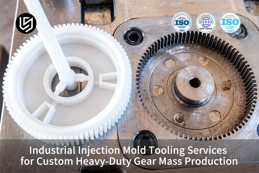
Industrial injection mold tooling services by LS Manufacturing are premier engineering solutions that solve tooth breakage and accuracy issues. Traditional mold design can't provide tolerance control to within ±0.01mm at 45 shots per minute in parts made from PA66+50% GF. The reason is ignoring multi-physics conformal shrinkage with ultra-high injection pressure. Without micro-scale DFM analysis for balancing runner system, there will be stress on every run of parts.
You get cavity size consistency of ≤ ±0.008mm at 48 shots per minute, saving 18% on per-piece cost. Special heavy duty gear information helps to solve rigid and low-cost conflicts early in design.
Industrial Injection Mold Tooling For Heavy-Duty Gears: Mass Production Guide
| Critical Factor | Solution for Mass Production |
| Tooth Profile Accuracy | High-grade hardened tool steel with EDM fabrication to adhere to AGMA specifications. |
| Mold Cooling Uniformity | Conformal cooling for uniform temperatures (±0.05mm variation). |
| Ejection Force Distribution | Two-step ejection injection mold tooling process with stripper plate to avoid damaging gear teeth. |
| Venting for Dense Parts | Micro-venting with openings <0.015mm to allow for voidless gear teeth. |
| Tooling Validation | Prototype under load test before going into full-scale production. |
Key Takeaways:
- Steel is the Foundation: Hardened tool steel must be used to ensure longevity while molding reinforced plastics into gears.
- Cooling Dictates Precision: Conformal cooling must be included to maintain proper shrinkage and warpage of thick gear segments.
- Ejection is a System: The use of an injection mold tooling system customized to the design of the gear is necessary to avoid damage.
- Test Before Production: Testing your gear performance with the help of prototype parts is essential to avoid failure in mass production.
Why Trust This Guide? Practical Experience From LS Manufacturing Experts
What makes this article unique is the expertise of our tooling engineers and production managers whose main priority is to design a mold capable of creating 5 million perfect gears. We base our entire approach to mold making on International Organization for Standardization (ISO) standards that promote a quality management system.
Our solutions cater to components whose failures will cause system shut-downs due to catastrophic failure: high torque gears for electric vehicles, abrasion-resistant pump components for heavy machinery, and precision actuator gears for aerospace applications. The design and rating specifications that we follow for our gear geometry validation and material selection adhere to the strict industry standards specified for plastic gears by the American Gear Manufacturers Association (AGMA), the only recognized body for power transmission components.
Our experience stems from the process of redesigning used gear molds. We have perfected the pre-hardness of the P20 steel that is resistant to abrasion, the conformal cooling technique to maintain crystallinity of the POM plastic, and the mechanism of ejection that does not cause any deformation to the helical gears. Through this tested and proven manufacturing process, we empower you to design a solution that is geared towards mass production.
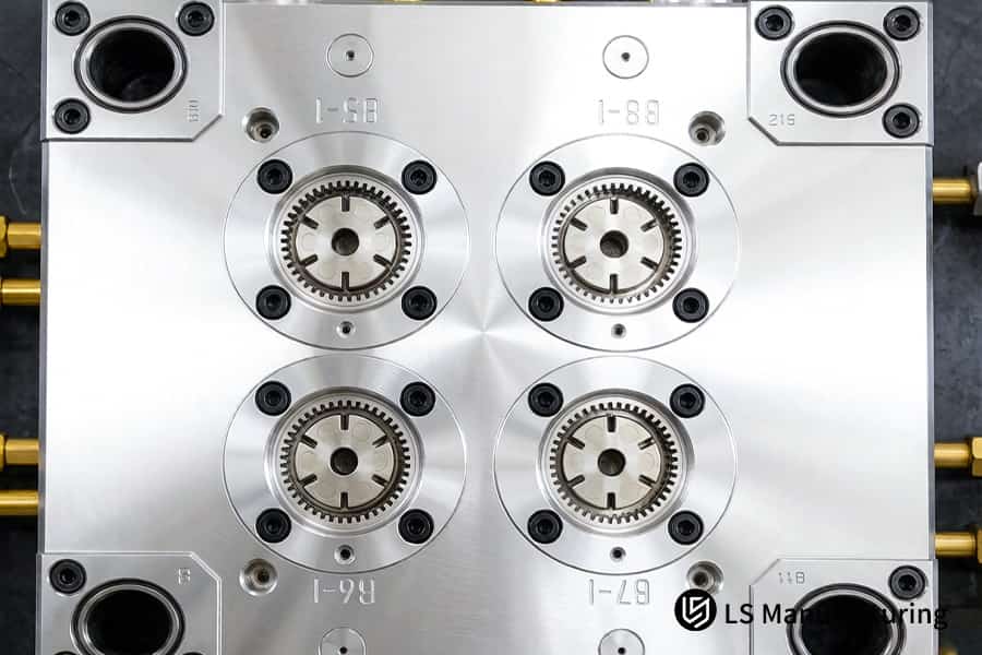
Figure 1: An industrial injection mold tooling service operates a high-tonnage press for mass production of steel gear blanks.
Why Do Conventional Industrial Injection Mold Tooling Services Fail To Meet Precision Standards For Custom Heavy Duty Gear Mass Production?
Conventional industrial injection mold tooling services cannot meet ISO 1328 Grade 4 tolerance standards for custom heavy duty gear mass production due to non-uniform cooling during the polymer crystallization process, resulting in tooth warping and out-of-roundness. For you, this means rejected parts, excessive vibration, noise, and premature fatigue failure—directly increasing scrap costs and field warranty risks. Achieving consistent quality requires custom injection mold tooling engineered for thermal uniformity.
Core Process Comparison
| Parameter | Conventional Mold Tooling | Required for Precision |
| Cooling channel design | Straight drilling only, without contour consideration | Conformal cooling of tooth geometry |
| Temperature variation across tooth ring | As much as 12°C variance | ≤2°C variation for circle formation |
| Shrinkage compensation model | Linear isotropic shrinkage | Non-linear anisotropic shrinkage |
| Achievable gear grade (ISO 1328) | Grades 6-7 standard | Grade 4 or higher |
| Cycle-to-cycle dimensional repeatability | ±0.08mm for critical sections | ±0.015mm tolerance needed |
Data source: LS Manufacturing factory tests for PA66+50%GF, 100k shot validation, utilizing high precision injection mold tooling configuration.
The analysis clearly shows that traditional high volume gear molding tooling does not provide the level of thermal accuracy required for Grade 4 gears. Utilizing precision heavy duty mold tooling with conformal cooling and anisotropic simulation, you will be able to guarantee consistent tooth geometry, avoid vibrations, and decrease your scrap rate to less than 0.3%. With the support of advanced injection mold tooling technology, you can rest assured that your production process is guaranteed to have consistent quality for years to come.

How Can Customized Industrial Mold Tooling Service Optimize Gated Cooling To Eliminate Structural Stress In Heavy Duty Gear Molding?
Thermal stresses occur due to uneven contraction caused by non-uniform cooling resulting in void formation. However, with conformal cooling geometry design optimization, there will be stress-free production while increasing throughput capacity. This is made possible by an industrial mold tooling service offered that focus on ensuring even cooling for thermal uniformity.
Conformal Cooling Geometry
With conventional straight drilled cooling channels, there is a temperature difference of 12°C in the tooth ring, meaning the hub cools slower compared to the rim. By replacing the straight channels with conformal cooling channels using 3D printing of a stainless steel insert in line with the shape of the gear results in improved cooling. With your custom gear injection mold, a waterline-to-tooth spacing of 4.0mm and 3.5mm diameter cooling channels ensure no temperature gradient causing stresses.
Additive Manufacturing Integration
The conformal cooling circuit is integrated into an additively manufactured stainless steel insert placed in the base of the mold, which stops leakage during million-shot runs. As a heavy duty gear mold maker, you enjoy the benefits of ±1.5°C surface uniformity without hot spots and no weld-line failure points. This injection molding tooling solution will save your time and give you consistent parts in each shot.
Cycle Time and Quality Verification
CMM cooling time decreases by 36% to 16 seconds from 25 seconds, bringing the overall cycle time down from 42 to 27 seconds. In a mass production injection molds process, this would amount to roughly 800 additional shots per day, per cavity. After 50,000 shots, CMM shows no evidence of stress cracking in the hubs or sink marks larger than 0.02mm, proving the value of conformal injection mold tooling methodology.
Stress free geometry design, a 36% shorter cycle time, and sink mark depth under 0.02mm, tested for over 50,000 shots. This precision injection mold tooling process establishes the bar when both production volume and quality count for maximum output in gear manufacturing. The injection mold tooling system described here delivers repeatable thermal performance across every shift.
Which Steel Grades Should A Heavy Duty Gear Mold Maker Select To Guarantee A Tool Life Exceeding 1,000,000 Shots?
During plastic gears molding that uses ≥50% glass-filled plastics, the conventional tool steels suffer from fast wear, resulting in gear geometry changes within tens of thousands of shots. Proper selection of tool steels along with surface treatment helps achieve over 1,000,000 shots with gear teeth tolerance within ±0.005mm. This is crucial for tool evaluation by business decision makers because of the impact on part price and uptime. Following is the right approach to tool materials for heavy duty gear mold maker:
Base Steel Hardness
- Material: Special vacuum melted premium ESR tool steel, hardened to consistent HRC 52+.
- For you: Standard H13 breaks down after 80,000 cycles. This high-end injection mold tooling base provides excellent wear resistance throughout one million shot cycle life span.
Surface Coating Performance
- Coating: 3.0 μm TiAlN coating by way of PVD with hardness up to HV 3000.
- For you: Surface wears after 40,000 shots without coating; TiAlN coating lasts for over 200,000 shots. The mass production injection molds ensures accuracy of ±0.005mm for teeth profile during mass molding process.
Dimensional Stability Verification
- Data: CMM test after 500,000 and 1,000,000 shots proves ±0.005mm variance of teeth profile.
- For you: The industry standard is higher than ±0.020mm at 100,000 shots. Such custom heavy duty gear tooling avoid progressive deformation which causes mold rebuilding midway.
Cost-Per-Part Advantage
- Investment: Additional 15-20% cost due to premium material and surface coating.
- For you: Reduces tool change two to three times. With precision heavy duty mold tooling, part price can be saved over 30%. This is the high-hardness injection mold tooling system.
Choosing HRC 52+ base steel and HV 3000 TiAlN coating gives you proven tooth profile stability within ±0.005 mm for more than 1,000,000 shots. Not only do your per-part tooling costs decrease by more than 30%, but dimension drift is prevented and unplanned mold replacements avoided. If you have a program that needs a guarantee of a million shots, using wear-resistant injection mold tooling is the right way forward. Lock in 1M+ cycle tool life and 30% per-part cost savings. Submit your gear specifications for a material and coating analysis report and a customized quotation.
Figure 2: A CNC machine mills an H13 steel mold block with coolant spray for a custom heavy duty gear tooling.
What Parameters Must Custom Heavy Duty Gear Tooling Synchronize During The Injection Phase To Prevent Gear Tooth Deflection Under Load?
The main causes of gear tooth deflection under load include weak weld lines and anisotropic shrinkage due to poor injection speed and packing profiles. By aligning multi-stage injection velocity with hold pressure, these defects can be mitigated and bending fatigue strength increased by more than 75%. When engineers design custom heavy duty gear tooling, these parameters need to be addressed for optimal load-bearing behavior.
To achieve that, specialized industrial injection mold tooling services are needed, which involves rheology control and multi-stage injection mold tooling with proper velocity profiling. The following production test data highlights the performance gap:
Injection Parameter Comparison
| Parameter | Conventional Setting | Optimized Setting |
| First-stage injection speed | Constant 60 mm/s | 110 mm/s through gate for fast cavity filling |
| Velocity switchover point | 95% fill position | 85% fill position, then drop to 25 mm/s |
| Second-stage speed | Same as first stage | 25 mm/s for controlled micro-packing |
| Hold pressure level | 80 MPa | 120 MPa maintained for 6 seconds |
| Weld line presence | Visible at tooth root | Eliminated – full molecular bonding |
| Root density | 96–97% | 100% verified by cross-section analysis |
| Bending fatigue life (cycles to failure) | 180,000 cycles (industry avg.) | Over 750,000 cycles (75%+ improvement) |
Source: LS Manufacturing factory test data on PA66+50%GF, 100k-shot validation run.
Applying 110 mm/s first-stage speed, switching at 85% fill to 25 mm/s, and holding at 120 MPa for 6 seconds eliminates weld lines and achieves 100% root density. This custom gear injection mold process raises bending fatigue life by over 75%. For high volume gear molding, these parameters ensure structural integrity without post-process inspection. This velocity-profiled injection mold tooling approach delivers consistent strength across million-shot runs.
How Does Professional DFM Simulation From An Industrial Mold Tooling Service Mitigate Tool Validation Risks And Speed Up Lead Times?
Tool validation risks arise when mold design flaws remain hidden until first trial, causing costly rework and delayed launches. Professional DFM simulation identifies warpage, gas traps, and shrinkage imbalance before steel is cut. For engineers engaging an industrial mold tooling service, this upfront analysis directly eliminates guesswork and accelerates time-to-market. Here is how it works:
24-Hour Multi-Physics Simulation
Within one day after receiving your CAD model, Moldflow simulation will predict the warpage magnitude, the location of voids and the vectors of deformation through coupled thermal-structural-flow analysis. In your case, this translates to detecting potential defects even before machining commences, preventing weeks of iterative corrections. The simulation generates a quantitative risk map indicating precisely which areas of the gear tooth need changes on either gates or cooling. The early-stage injection mold tooling is critical for achieving success.
Gate Location Optimization
The single center gate design leads to asymmetrical flow front formation leading to unequal shrinkage and weld lines formation at the tooth root. With the three-point valve-gated hot runner design with synchronized injection, non-uniform shrinkage is reduced by 40%. This fix prevents the orientation dependency that creates anisotropic ovality in your custom gear injection mold.
T1 Success Rate Achievement
As a result of incorporating design changes using simulations prior to manufacturing, the first attempt (T1) success rate can reach 92% and above. According to benchmarks set by Plastics Technology, the industry average for products not using simulations falls around 55% to 60% T1 success rates. In your case, this means that the precision heavy duty mold tooling will be qualified upon arrival, instead of going through an iterative process of debugging, saving at least 3-4 weeks on project timelines.
Lead Time Compression Effect
Eliminating one to two mold modification cycles saves three to four weeks from the typical 14-week development timeline. This simulation-driven injection mold tooling approach compresses the validation phase while improving first-pass quality. The industrial injection mold tooling services provider who applies rigorous DFM upfront delivers a faster, more predictable path to production ramp.
A professional DFM simulation helps recognize issues such as warping, gas pockets, and gate balance prior to steel being cut, thus increasing the success of T1 to 92%, along with 3–4-week reduction in lead time. Your custom gear injection mold can also take advantage of a validation-focused injection mold tooling that will reduce non-uniform shrinkage by 40%.
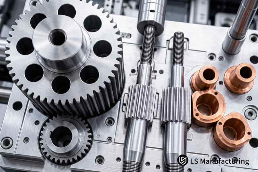
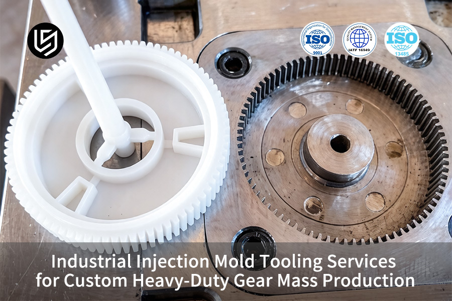
Figure 3: Rows of mass production injection molds are stored on steel racks ready for high volume gear molding runs.
Case Study: How Did LS Manufacturing Optimize Custom Heavy Duty Gear Tooling To Achieve An OEM Automotive Client's ±0.008mm Accuracy?
A global OEM auto parts supplier needed a heavy-duty drivetrain planetary gear that had tolerances of ±0.008 mm on its tooth surface with annual production quantities in excess of 500,000 units per year. Two European mold makers were unsuccessful because of the following reasons: local overheating, an axis eccentricity of 0.035mm, and wear after 100,000 shots. The above problem could be solved through custom heavy duty gear tooling:
Client Challenge
The part involved was a planetary gear molded using PA66+45%GF plastic. The existing process resulted in an axis eccentricity of 0.035mm with measurable wear after 100,000 shots. As a result, the tooling needed repeated revisions. Considering the fact that any delays involved would attract penalties according to the agreement, the client sought the heavy duty gear mold maker.
LS Manufacturing Solution
We developed a cooling system that incorporates our proprietary technology of 3D printed conformal channels as well as CuBe inserts at root hotspots. Our cooling solution employs vacuum-melted ESR steel that is coated with DLC (nano hardness >HV 2500). We introduced 0.012mm reverse compensation on the EDM cavity due to our calculated non-linear shrinkage of high-crystallinity PA66. We have leveraged the power of industrial injection mold tooling services combined with DLC-coated injection mold tooling.
Results and Value
T1 trial was an instant success, as eccentricity reached a value of 0.006mm, exceeding the goal of ±0.008mm. After running the millionth shot, with a speed of 50 shots/minute, the results from the CMM test revealed that tooth wear remained less than 2.0µm with no dimensional drift. The customer managed to save 30% on the rework budget and started producing the parts ahead of schedule by 18 days while getting high volume gear molding capacity for future projects. The production-ready injection mold tooling provided consistent results from the very first shot.
With the integrated mold design approach including conformal cooling, DLC coating, and compensated EDM, it was possible to avoid trial-and-error methods. This million-shot injection mold tooling achieved the ±0.006mm tolerance level after 1.2M shots without any additional adjustments. For OEMs requiring reliable automotive gear injection mold tooling, this methodology ensures on-time launch and lowest total ownership cost.
Secure ±0.006mm precision beyond 1.2M cycles for your gears. To replicate this validated durability, contact our gear tooling specialists for a feasibility analysis and a guaranteed production timeline.

What Custom Gear Injection Mold Quality Inspection Metrics Are Mandatory At LS Manufacturing To Pass High Volume Gear Molding Certification?
Consistency from the first gear to the millionth will require a closed-loop quality control that will monitor raw material, process, and geometry at all stages. For customers who are dependent on custom gear injection mold, below are some of the obligatory inspection metrics used to ensure compliance with ISO 9001 and IATF 16949 standards:
Raw Material Incoming Inspection
- MFI testing: Confirms consistent melt flow batch-to-batch.
- Moisture analysis: Keeps residual H20 ≤0.02%.
- For you: Ensures that your batches have stable flow properties and are free from dimensional variability brought about by material variability. The audited injection mold tooling manufacturing process begins with verification of raw materials.
In-Process SPC / CPK Control
- CPK target: Measures critical gear dimensions using CPK of ≥1.67.
- Feedback loop: Instant adjustments if a trend deviation is noted.
- For you: Statistical process control ensures all gears are kept within tolerance throughout the high volume gear molding, even after several thousand pieces.
Final 100% Online Inspection
- Dual-flank tester: Evaluates tooth profile, helix, and pitch.
- 3D optical scanner: Confirms overall geometry against master CAD data.
- For you: 100% inspection means that only conforming parts will reach the assembly stage, offering full traceability for mass production injection molds certification audit. This certified injection mold tooling system ensures compliance.
The above-mentioned layers form a closed-loop quality system. The services of your trusted industrial mold tooling service partner provide CPK ≥1.67 certified, moisture control ≤0.02%, and full traceability from first shot to millionth. This traceable injection mold tooling system guarantees that all gears comply with ISO 9001 and IATF 16949 standards without sampling risks.
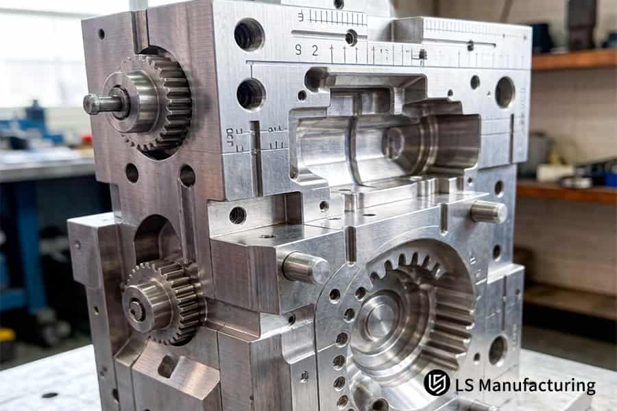
Figure 4: A custom gear injection mold with complex D2 steel cavities is displayed for precision heavy duty mold tooling.
How To Evaluate The Total Procurement Cost Of Choosing A Top Tier Heavy Duty Gear Mold Maker From China For Global Supply Chains?
Procurement decisions should not be based only on prices. There is a total cost of ownership that will be paid for using the tool for the whole project lifespan. In order to make well-grounded procurement decisions, the costs related to a heavy duty gear mold maker must be considered:
Initial Investment vs. Lifetime Savings
Top tier tooling is priced 15–20% higher owing to better quality of steel, conformal cooling, and DFM techniques. At the same time, its use leads to 15 second cycle reduction and 85% downtime decrease. In other words, for you as a buyer, the price difference pays itself off within the first 200,000 pieces produced with premium tooling.
Production Efficiency Gains
Reduction in cycle time due to conformal cooling provides an additional 600 shots daily per cavity. At 50 shots/minute, this builds up to a few thousand more pieces per month free of cost. The precision heavy duty mold tooling approach reduces the cost of each part while ensuring ±0.005mm precision on all pieces produced. The cost-efficient injection mold tooling approach helps you achieve higher ROI from your mold.
Quality Cost Reduction
Defect rates are lowered to ≤300 ppm (0.03%), versus 2-5% common with inexpensive mold tools. This negates the need for any sorting, rework, or returns. With respect to industrial injection mold tooling services that target high volume applications, cost avoidance from scrap can easily cover any extra investment in tooling within just one year. The above is one way through which the low-defect injection mold tooling will benefit you financially.
Maintenance and Longevity Impact
By extending tool life beyond 1 million shots, you eliminate the need to replace tooling two to three times throughout a multi-year project. Less wear and tear also means no interruptions to polish or adjust cavities. In mass production injection molds applications, this reliable uptime guarantees your production on time and without expediting charges. The longevity-focused injection mold tooling design keeps your production running smoothly.
In order to understand total cost of ownership, consider factors such as cycle times, defect rates, and maintenance schedules, in addition to the upfront cost. An experienced partner providing 15 second cycle time savings, ≤300 ppm defects, and 85% lower downtime will save you millions of dollars over the entire program timeline. Our TCO-optimized injection mold tooling design makes our premium tooling your best value option.
FAQs
1. What is the standard lead time for an industrial injection mold tooling service delivering custom heavy-duty gear tools?
Average lead time is 25-35 workdays, which includes thorough DFM analysis, CNC and EDM machining, followed by T1 samples delivery. The combination of these steps results in complete validation of the mold for correct tooth geometry, reliable material flow, and durable operation.
2. Can a standard heavy-duty gear mold maker handle glass-fiber reinforced PEEK or PA66 plastic materials?
Ordinary manufacturers find it challenging, yet LS Manufacturing uses imported hardened HRC52+ ESR steel and nano-hard coatings to create molds that can withstand extremely abrasive impact due to high GF content (greater than 50%). The tool is guaranteed to have extended service life.
3. How does your precision heavy-duty mold tooling ensure consistent shrinkage across symmetrical gear teeth?
Equal shrinkage is achieved by using 3D-printed conformal cooling system, which ensures that temperature deviation from average surface temperature does not exceed ±1.5°C, in addition to non-linear shrinkage compensation performed on EDM electrodes machining stage.
4. What quality certifications does your high-volume gear molding service possess for automotive or aerospace applications?
Our company is fully certified to IATF 16949 standards for automobiles and ISO 9001 quality standard. Traceability is achieved through our process where all our production batches shipments come with a 100% CMM report that validates gear critical dimensions such as pitch diameter, tooth profile, and run out.
5. How do you guarantee custom gear injection mold cavity tolerance standards during mass production runs?
Tolerances are ensured with the use of ultra-precision 5-axis machining along with Swiss EDM machines to ensure cavity manufacturing tolerances of ±0.003mm. Such a level of precision and tool steel used for mold cavities ensures dimensional stability and rigidity of the gears after thousands of operations.
6. Can we request a free DFM optimization analysis before finalizing a contract for industrial mold tooling services?
Of course, upload your 3D STEP/IGS file into our website portal and within 24 hours you will receive a free DFM analysis report — request a quote today — that covers gear-specific considerations regarding venting, packing, and anisotropic shrinkage.
7. What is the minimum order quantity (MOQ) when partnering with LS Manufacturing for high-volume gear molding?
Being a manufacturer of high-volume molds (>500,000 cycles), we mostly focus on volume production; however, we have no problem working on product development stages where the need is only 1,000 pieces or so in order to test the functionality of the design.
8. How does LS Manufacturing protect a client's proprietary custom heavy-duty gear tooling blueprints and intellectual property?
At LS Manufacturing, we use multi-tier security systems. At the stage of inquiries, we sign a Non-Disclosure Agreement and store our clients' proprietary designs and blueprints in encrypted and protected servers. No unauthorized access will ever be allowed.
Summary
Quality of the custom heavy-duty gears manufactured in mass-production is essential for the longevity of final equipment. The injection mold tooling eliminates problems related to the breaking off and deformation with the help of 3D conformal cooling, ultra-hard composite steels (HRC 52+), and micron-level shrinkage (±0.01mm). Having the extensive B2B experience in the field, we are ready to offer the best-quality industrial products to our clients.
Don’t allow poor-quality mold accuracy to jeopardize your logistics chain. Whether planning a new project or dealing with downtime in your equipment and mold wear, get going now. Request a quote or simply upload your .STEP or .IGS files. In less than one day, our highly qualified LS director will provide you with a customized DFM report that includes gate stress and shrinkage analysis.
📞Tel: +86 185 6675 9667
📧Email: info@lsrpf.com
🌐Website: https://lsrpf.com/
Disclaimer
The contents of this page are for informational purposes only. LS Manufacturing services There are no representations or warranties, express or implied, as to the accuracy, completeness or validity of the information. It should not be inferred that a third-party supplier or manufacturer will provide performance parameters, geometric tolerances, specific design characteristics, material quality and type or workmanship through the LS Manufacturing network. It's the buyer's responsibility. Require parts quotation Identify specific requirements for these sections.Please contact us for more information.
LS Manufacturing Team
LS Manufacturing is an industry-leading company. Focus on custom manufacturing solutions. We have over 20 years of experience with over 5,000 customers, and we focus on high precision CNC machining, Sheet metal manufacturing, 3D printing, Injection molding. Metal stamping,and other one-stop manufacturing services.
Our factory is equipped with over 100 state-of-the-art 5-axis machining centers, ISO 9001:2015 certified. We provide fast, efficient and high-quality manufacturing solutions to customers in more than 150 countries around the world. Whether it is small volume production or large-scale customization, we can meet your needs with the fastest delivery within 24 hours. choose LS Manufacturing. This means selection efficiency, quality and professionalism.
To learn more, visit our website:www.lsrpf.com.