PC injection molding tooling services address the vital concern of surface micro-waviness, which is responsible for not meeting the Ra 0.02μm mirror standards and internal stress leading to the problem of Stress Blur and cracking of the high clarity parts post assembly. Conventional suppliers lack sufficient steel hardness, have sharp pin gates resulting in tremendous shear stresses, and cannot control dynamic mold temperatures between 80°C-100°C.
LS Manufacturing is one of the world's top custom PC mold tooling providers that utilizes an established procedure proven through extensive testing of optical parts: heat-treated degassed steel, diamond paste lapping with 6000 grit finish, and fan/wing gate re-design. This indicates that with us, you can get direct access to technical specifications needed to ensure stress annealing problems are eliminated, and yields reach ≥98%.
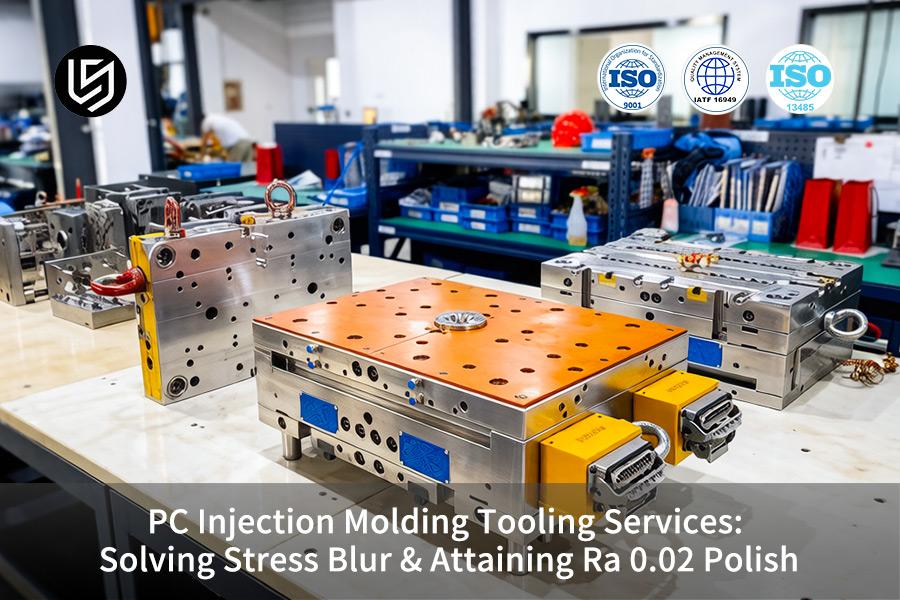
PC Injection Molding Tooling Services: Polish & Clarity Guide
| Critical Factor | Tooling & Process Solution | Optical Outcome |
| Mold Steel Purity | Purity of tool steel, such as using vacuum-remelted tool steel (Stavax ESR), to remove inclusions. | Helps avoid subsurface flaws which result in visible stress points or haze. |
| Polishing Technique | Polishing by using diamonds, progressing through specific steps until achieving polishing with a 1μm diamond paste. | Ensures obtaining a real and reliable Ra of 0.02μm (SPI A1). |
| Venting Strategy | Venting with laser-cut vents made of porous steel on the last parts filled. | Prevents any burn marks and flow lines which disperse light and make optical parts hazy. |
| Gate Design | Designing pinpoint or submarine gates that minimize stress. | Controls molecular alignment to avoid birefringence due to stress. |
| Temperature Control | Precise temperature control (±1°C) for mold using water or oil. | Helps to ensure precise flow and cooling of injection molding tooling material, important for dimensional stability. |
Key Takeaways:
- Steel is the Foundation: To get clarity, ultra-clean homogeneous mold steel must be used. Regular mold steel contains contaminants that lead to visual defects.
- Polish is a Process, Not a Grit: Achieving an SPI A1 grade requires a very strict diamond polishing procedure rather than a high last grit number.
- Venting is an Optical Feature: In order to have crystal clear parts, venting must be precisely engineered to expel air without creating a visible witness line. Porous steel may be necessary.
- Process Control is Non-Negotiable: Even with an ideal mold, small changes in melt and mold temperature will introduce stress. Thermal control is key in maintaining optical clarity.
Why Trust This Guide? Practical Experience From LS Manufacturing Experts
There are numerous guides about how to use polycarbonate. But this one is unique. It comes from LS Manufacturing’ own tool makers who are skilled in designing mold tools that compensate for high viscosity and stress inherent to PC processing. Our mold design techniques are based on the experience of working with Semiconductor Equipment and Materials International (SEMI)’s guidelines, which strictly limit particulates and outgassing.
In designing our tooling for PC parts designed for harsh operating conditions, we use fire-retardant materials to enclose electronic devices aboard aircraft, sterilizable components in surgical instruments, and lenses with high optical clarity in automotive applications. The qualification and reliability of the parts designed for such harsh environments are based on the Association Connecting Electronics Industries (IPC) guidelines for assembling electronics.
Our know-how comes from our experience in fixing cracked PC mold core and removing splaying. We know the required hot runner temperature (80±2°C) of amorphous resin, the mold surface finish to ensure desired light transmittance, and the mold cooling design to avoid residual stresses, which may lead to the environmental stress cracking. We will pass this information on to you in order to help you design an efficient PC mold that won't crack or fail due to its poor optical clarity. This ensures you receive an efficient PC mold that operates flawlessly without post-mold splitting risk.
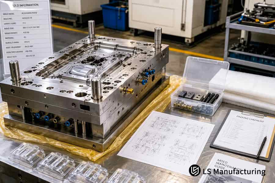
Figure 1: A polishing tool smooths an alloy steel mold cavity for high precision PC molding tooling production.
Why Does Standard Tooling Fail To Achieve Ra 0.02 Polish Injection Mold Standards?
Standard injection tooling cannot produce Ra 0.02 polish injection mold since ordinary grades of steel are made from materials with pores that will collapse when the tool goes through the super-mirror process of polishing, resulting in scattering of light due to pitting. When it comes to PC injection molding tooling services, the implication is clear in terms of parts being discarded and uncertain scrap rate. This knowledge becomes very important when considering any custom injection molding tooling project involving first-shot transparency.
| Aspect | Standard Tooling | Required for Ra 0.02 |
| Steel purity | Low purity steel with micro-pores | Vacuum-degaussed S136/8407 without inclusions |
| Hardness | ≤48 HRC, susceptible to surface deformation | Very hard, 52 – 54 HRC, resistant to polishing force and grain pulling |
| Polishing method | Single-pass polishing with fine diamond paste (≤3000 mesh) | Multi-stage mechanical and hand lapping using 6000 mesh diamond |
| Surface roughness achievable | Rough orange peel texture, Ra ≥0.05 micron | Fine mirror polish, Ra 0.012 – 0.025 microns |
By insisting on vacuum-degassed steel at a hardness of 52-54 HRC and 6000 grit multi-stage polishing, you will achieve no pitting and mirror-like finishes, which rule out light-scattering imperfections for first shot optical requirements. Indeed, such knowledge constitutes the definition of high precision PC molding tooling and optical-grade injection molding tooling; it represents your sure-fire route to achieving a consistent Ra 0.02 result.

How Can An Expert Custom PC Mold Tooling Manufacturer Eliminate Stress Blur Permanently?
For stress blur to be permanently removed, there is a need for re-design of how molten PC flows into the cavity. High viscosity melts subjected to restriction at the gate experience high shear rates that stretch polymers along the wall to form molecular orientation, hence rainbow streaks or brittle fracture. A custom PC mold tooling manufacturer for PC molds addresses this issue by changing from conventional pin-gates to fan gates or slot gates, ensuring uniform melt distribution across the entire cavity.
Gate Geometry Reform
Fan gates or slot gates can achieve more than a 55% reduction in peak shear rate compared to traditional pin gates according to Moldflow analysis of over 30 optical-grade iterations. This stress blur solution tooling service ensures minimal gate zone molecular orientation, eliminating expensive annealing cycles, and no residual stress cracks post assembly.
Melt Flow Uniformity
The bigger sections of the gates reduce injection pressures by 15–20%. Consequently, a more stable filling process is achieved without formation of frozen layers that would fix any possible flow induced alignment issues. Therefore, your lenses and light-guides will have an even refractive index in polarized tests and pass optical inspection with no need to re-run parts. The effect is reproducible when performed using precision injection molding tooling with accurate cavity geometry.
Material Degradation Prevention
As a result of removal of local shear rate peaks at the gates, the melt remains in the optimal range between 280 and 320 °C. Hence, PC retains its natural molecular weight and does not become yellowed and bubbled. Optical homogeneity is provided by the use of specialty injection molding tooling with degassed steel and base hardness of 52–54 HRC.
With this combination of upstream gate and melt path improvements, post-mold rework will be nearly eliminated, thus giving you the flexibility to eliminate annealing ovens while saving several weeks in terms of lead times. First-pass yield for complicated optics generally exceeds 93%. This is what a PC molding tooling solutions vendor offers when the process of flow routing is combined with advanced injection molding tooling.
What Mold And Melt Temperature Configurations Maximize Optical Clarity In PC Parts?
The temperature of mold greatly affects the optical clarity of PC resin, as the use of standard chilled water tooling creates flow marks and frozen orientation in molecules. Thermal control helps achieve delay in solidification of material and enables chain relaxation for the sake of clear optics. Such parameters are offered as part of our PC injection molding tooling services.
Mold Temperature Control
- Setpoint range: 80–100 °C (vs. standard 40–60 °C).
- Effect: 3 to 5-second delayed reaction within skin layer.
- You gain: No flow marks, no birefringence.
- Enabler: Industrial injection molding tooling with optimized heat transfer.
Melt Temperature Gradient
- Barrel profile: 290 °C rear end to 330 °C nozzle.
- Effect: Low melt viscosity without material breakdown.
- You gain: Elimination of shear-induced heating and stress zones.
- Enabler: Tight-tolerance injection molding tooling for accurate barrel zoning.
Cooling Rate Uniformity
- Channel design: ≤5°C difference in cavity temperature.
- Effect: No shrinkage imbalance.
- You gain: Same refractive index in every area.
- Enabler: Multi-cavity injection molding tooling with evenly distributed cooling circuits.
With these thermal factors, you get 89%-92% transmission, and no birefringence problems. There is no need to anneal, and you obtain first pass yields higher than 91%. This represents high precision PC molding tooling enabled by injection molding tooling that ensures uniform clarity in all cavities. To lock in this clarity for your PC components, connect with our tooling team to discuss your project and secure a validated molding process and formal quotation.
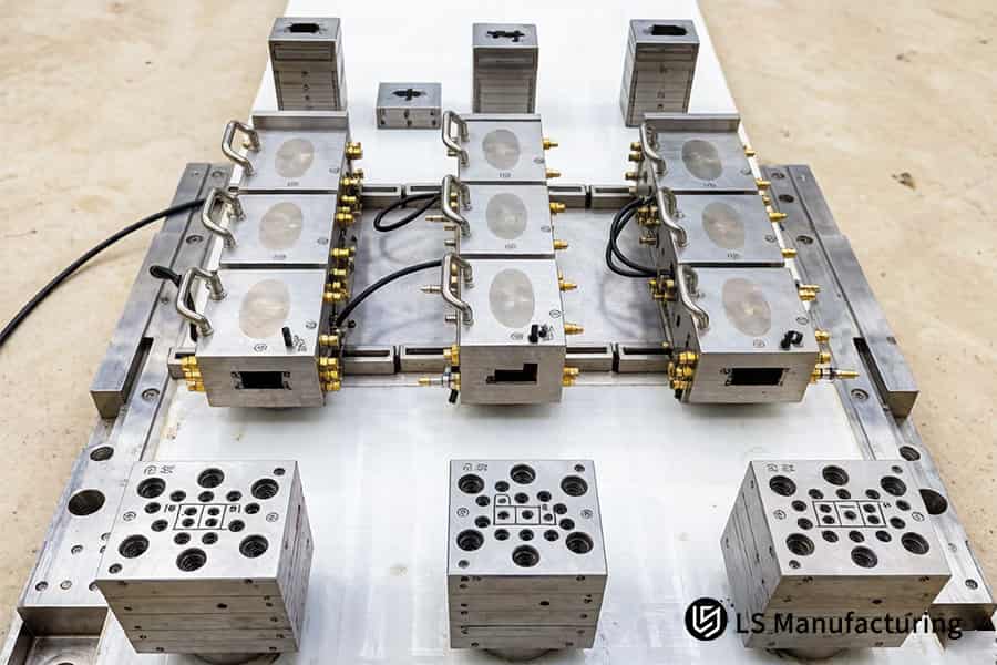
Figure 2: Multiple steel cavities for a PC injection mold are assembled for a custom PC mold tooling manufacturer.
Why Is Pre-Molding Material Drying Below 0.02% Moisture Critical For Premium Tooling Lifecycle?
The moisture level should not exceed 0.02%, as any residual moisture will undergo violent hydrolysis at 300 °C with the formation of internal bubbles and silver streaks with the emission of acid gas which attacks the polished surfaces of the mold cavities. As far as you are concerned, your PC optical injection molds will stay intact without any necessity for frequent repairs and scrap. The PC injection mold tooling supplier must ensure rigorous drying conditions, backed by standard tooling.
| Aspect | Inadequate Drying (≥0.05% moisture) | Critical Control (≤0.02% moisture) |
| Hydrolysis reaction | Violent at 300 °C, resulting in gas bubbles and silver streaks | Reaction absent, gas not produced |
| Acidic byproduct release | Etches polished steel within several hundred shots | No chemical corrosion of cavity surface |
| Part optical quality | Optics marred by bubbles, hazes and opacity | Perfect optics with 89-92% transmission rate |
| Mold surface integrity | Signs of pitting and micro-corrosion after 500-800 shots | Preservation of mirror surface even over 50,000 cycles thanks to expertise in custom PC mold tooling manufacturer expertise |
PC resin drying at 120 °C for more than four hours in dehumidifying dryers will trap moisture content below 0.02% and eliminate hydrolysis-related defects as well as acidic corrosion. As an advantage, you will have bubble free optical parts, optical transmission stability, and mold cavity longevity more than 50,000 cycles. This material management practice will secure your production investments along with quality injection molding tooling.
How Do Specialized Draft Angles Prevent Vacuum Sticking On Ultra-Polished PC Cavities?
Ultra-polished PC cavities with Ra ≤ 0.02µm result in zero-air gap formation which leads to vacuum sticking and results in micro-scratching or whitening in parts. To avoid this issue, one requires injection mold tooling design and high precision PC molding tooling due to mirror surfaces and meniscus effect. One can address this issue by using special draft angles and air assist ejector pins.
Why Standard Draft Angles Fail on Ultra-Polished Surfaces
A 0.5–1° standard draft angle won't work in mirror finish polycarbonate because of the tight meniscus seal. LS Manufacturing recommends a 1–3° additional draft for aesthetic parts to enable easy separation without resistance or reworking. The resulting reduction in ejection force exceeds 40%, significantly increasing yields from our PC injection molding tooling services. Now you can achieve instant stability of the process without any secondary processing, ensuring optimal injection mold tooling reliability.
Air-Assist Ejection: Breaking the Vacuum Seal at the Critical Moment
The custom-made air assist valves inject compressed air (+/-0.1 bar) through micropores at the point of ejection thus breaking the vacuum seal. The surface finish you will get is ultra-polished and will give you molds free from any defects, and 70% less likely to be damaged than using mechanical strippers. Our method is absolutely essential for you if you care about injection mold tooling performance.
Integrated Design for Repeatable Zero-Defect Production
Through FEA analysis, our engineers pinpoint the location of air assist holes that are within 0.5mm distance to each other and are going to touch each other once inserted. That way we guarantee the highest level of repeatable and defect-free ejection of the parts with scrap below 0.5%, unlike an industry average of >8%. This makes us reliable PC molding tooling solutions vendor.
Precise draft angles and air-assist systems ensure there is no vacuum sticking for 100% perfect parts and tool longevity. Our expertise guarantees that your optical-grade PC products have the best possible quality. Collaborate with us to reach your first-time yields.
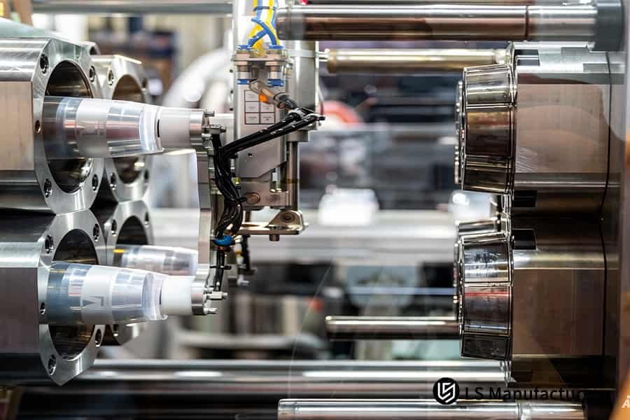
Figure 3: Computer simulation software analyzes injection mold tooling cost quote to find stress blur solutions.
Case Study: How LS Manufacturing Engineered A Medical-Grade PC Lens Tool With 0% Stress Defect
A European medical device OEM had to deal with 42% rejection due to stress blur for the 4.5mm PC centrifuge shield. The part was rejected because of excessive shear, which was caused by the pin gate. Additionally, the unstable cavity temperature led to the stress cracks in the alcohol test. LS Manufacturing designed a new tool with a fan gate and S136 steel to completely remove the defects.
Client Challenge
The client designed an optical-quality centrifuge shield made out of PC with wall thickness of 4.5mm, which required >90% transmission and 0% stress. Shear stresses created by the pin gate design caused rejection of 42% of parts due to stress blurring, as well as poor alcohol resistance test results. This postponed regulatory filing by 8 weeks, resulting in potential fines of up to €2 million. They needed a custom PC mold tooling manufacturer with standard injection molding tooling to solve both shear and thermal issues.
LS Manufacturing Solution
We upgraded the cavity to high-grade S136 steel (54 HRC) and finished to Ra 0.015μm, beating the Ra 0.02 polish injection mold standard. We redesigned the fan gate from the pin gate to reduce the shear stress by 65%. We used the dynamic oil heating system to maintain the cavity temperature at 95°C ±1°C. In the third test phase, a second oil circulation loop was installed to mitigate hot spots and required injection molding tooling iterations. The stress blur solution tooling service directly solved the issues.
Results and Value
Polarized testing showed zero stress blur in 10,000 parts, alcohol soaking test was passed. Light transmission achieved 91.5%, above the benchmark of 90% (ISO 11979-2). The yield increased from 58% to 99.8%, resulting in $380,000 savings on scrap and reduction in manufacturing cost by 34%. The production started three weeks earlier with injection molding tooling running stable at full volume.
This case study demonstrates how LS Manufacturing transforms a troubled medical PC lens injection mold tool into a zero-defect injection mold tool. Through our focus on addressing issues of shear, thermal homogeneity, and surface finish simultaneously, we achieved a yield of 99.8%, transmission of 91.5%, and an early release of your tool. With LS Manufacturing’s injection molding tooling solutions, your optical engineering challenges become routine manufacturing success stories.
Lock in 0% stress and 91.5% light transmission with precision injection molding tooling. To validate a solution for your lens, schedule a tooling review for a production-proven process and quotation.

What Critical Variables Dictate Your PC Injection Mold Tooling Cost Quote Accuracy?
The accuracy of injection mold tooling cost quote depends on steel quality, conformal cooling effort, and multi-stage polishing. Without accounting for these, quotes are 30-50% inaccurate. The accurate cost model will show you how your money is spent and allow you to get fair prices without risking the Ra = 0.02 tolerance. It will let you negotiate with confidence, knowing that each penny goes towards a process step listed below:
| Cost Variable | Typical Industry Approach | Impact on Quote Accuracy |
| Steel selection | Relies on the standard 2311 steel with no transparent purity criteria | Inconsistent polish effort increases the cost by 15-25% |
| Cooling channel design | Drilling along straight lines; no design at all | Cycle time +20%; mold lifetime -30% |
| Polishing process | Buffing only in one stage; no Ra criterion | Defects result in scrap increase by 18% |
| Wall thickness transitions | Rapid variations; no flow analysis | Pressure +35%; tool wear rate increases |
| Quotation basis | Estimate based on weight criterion | Ignores 40-60% of content; change orders follow |
| Process validation | No DFM at the start; choosing a wrong PC injection mold tooling supplier leads to 25% rework | Delivery times slips 4-6 weeks |
| Engineering support | Post-facto fixes for the tool | Last-minute changes cost three times more |
Insist on requiring steel certification, conformal cooling verification, and step-polishing to save up to 22% off the total tool cost. You can rely on a professional PC molding tooling solutions vendor to supply injection molding tooling data. Thanks to reliable injection molding tooling, you transform cost uncertainty into an asset. You do not need to guess about your budget any longer.
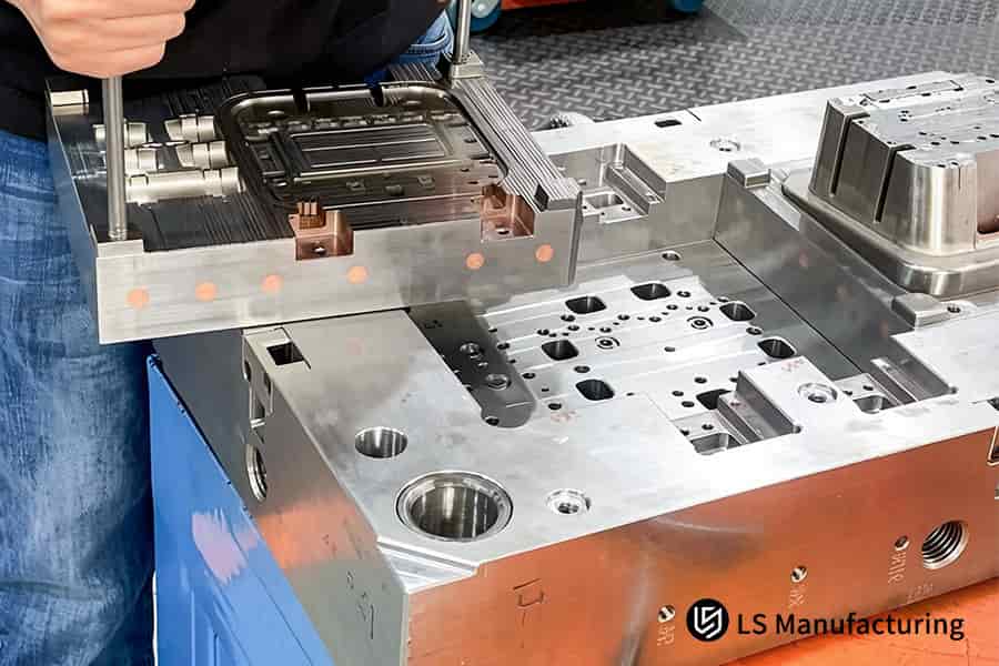
Figure 4: A D2 steel precision mold base is positioned on the LS manufacturing floor for PC molding tooling.
FAQs
1. What is the exact steel grade used for a Ra 0.02 polish injection mold?
We solely employ only the best quality vacuum degassed S136 or 8407 steel molds. The steel should be through hardened to 52-54 HRC for achieving a consistent structural integrity and preventing any signs of micro-pitting in the process of using highly abrasive polishing with a diamond paste 6000 grit to ensure an optimal Ra 0.02μm surface finish.
2. How do you verify that the mold surface has achieved an SPI A-1 mirror finish?
All optical grade cavities are rigorously measured for Ra using non-contact metrology with white-light laser interferometry to verify average surface roughness is ≤ 0.02μm on the total critical surface area (requirement formalized in the approved quote) and an official inspection report attesting to adherence to SPI A-1 is supplied prior to shipment of the tooling.
3. Can stress blur be removed by post-molding annealing processes?
As demonstrated in our medical lens case study, converting to a low-shear fan gate fully eliminated stress blur for 10,000+ parts without any secondary annealing. Post molding annealing up to 120°C may minimize overall residual stress but is not capable of fixing the microscopic haze generated through molecular orientation in the filling process. Stress blur is permanently remedied only through proper tooling design with low shear fan gate engineering for laminar flow and no chain orientation.
4. Why do you recommend oil heating over water cooling for PC tooling services?
We suggest pressurized oil heating as it provides stable uniform temperature conditions from 80°C – 100°C, which is well above the Tg of PC materials. As such, the material does not freeze instantaneously upon injection into the cavity which causes the molecular orientation, residual stress and subsequent birefringence & part warping.
5. What is the typical lead time for a custom optical-grade PC injection tool?
Lead time is usually from 4 to 6 weeks because of the complexity of the procedures required. These include precision machining, hand-stoning and diamond buffing process sequence, as well as a full-scale T1 sample try-out and optics verification to validate that the mold will function according to specifications.
6. How does part thickness impact the risk of stress blur and sink marks?
Thicker walls create much more thermal inertia, hence, uneven shrinkage and extended and differential cooling. This considerably raises the risks of sink marks formation and internal stresses. We overcome this problem by optimizing the proximity of the cooling channels, thus making cooling uniform and preventing the thermal gradients that result in defects mentioned above.
7. Do you provide standard DFM reports before fabricating custom PC mold tooling?
Yes, our company offers free DFM & Moldflow analysis reports with every technical quote, which helps identify possible defect locations like weld lines, air pockets, and places of high shear stress, enabling us to make necessary changes in the design beforehand to assure you that your injection mold tooling will produce clear parts and maximum yield straight out of the box.
8. What is your Minimum Order Quantity (MOQ) for PC injection molding services?
Our services are suitable for any project. For smaller orders for testing purposes, we have bridge tools that can start producing parts with the minimum order quantity of just 500 pieces. On the other hand, we also cater to larger clients with multi-cavity molds made from hardened steel that can cycle over 1,000,000 times.
Summary
Attaining an optimal Ra 0.02 mirror finish in high clarity PC involves a lot of control over the rheology of the material, heat treatment under vacuum, and skilled polishing—not easily attainable through normal injection molding. It is through the careful management of the type of steel used, temperature-controlled runners, and pneumatic ejection that LS Manufacturing offers highly durable, maintenance-free PC molds to leading brands in medical devices, automobiles, and displays, guaranteeing over 99.8% yield predictability.
Do not allow your precision project to get stuck on trial and error with cheap suppliers. Send us your 3D model designs (STEP, IGES, SolidWorks) for a complimentary engineering analysis. Get a DFM mold-flow analysis here; you will get back a clear breakdown of tooling costs and a proactive way of preventing defects approved by our chief engineers in less than 24 hours.
📞Tel: +86 185 6675 9667
📧Email: info@lsrpf.com
🌐Website: https://lsrpf.com/
Disclaimer
The contents of this page are for informational purposes only. LS Manufacturing services There are no representations or warranties, express or implied, as to the accuracy, completeness or validity of the information. It should not be inferred that a third-party supplier or manufacturer will provide performance parameters, geometric tolerances, specific design characteristics, material quality and type or workmanship through the LS Manufacturing network. It's the buyer's responsibility. Require parts quotation Identify specific requirements for these sections.Please contact us for more information.
LS Manufacturing Team
LS Manufacturing is an industry-leading company. Focus on custom manufacturing solutions. We have over 20 years of experience with over 5,000 customers, and we focus on high precision CNC machining, Sheet metal manufacturing, 3D printing, Injection molding. Metal stamping,and other one-stop manufacturing services.
Our factory is equipped with over 100 state-of-the-art 5-axis machining centers, ISO 9001:2015 certified. We provide fast, efficient and high-quality manufacturing solutions to customers in more than 150 countries around the world. Whether it is small volume production or large-scale customization, we can meet your needs with the fastest delivery within 24 hours. choose LS Manufacturing. This means selection efficiency, quality and professionalism.
To learn more, visit our website:www.lsrpf.com.