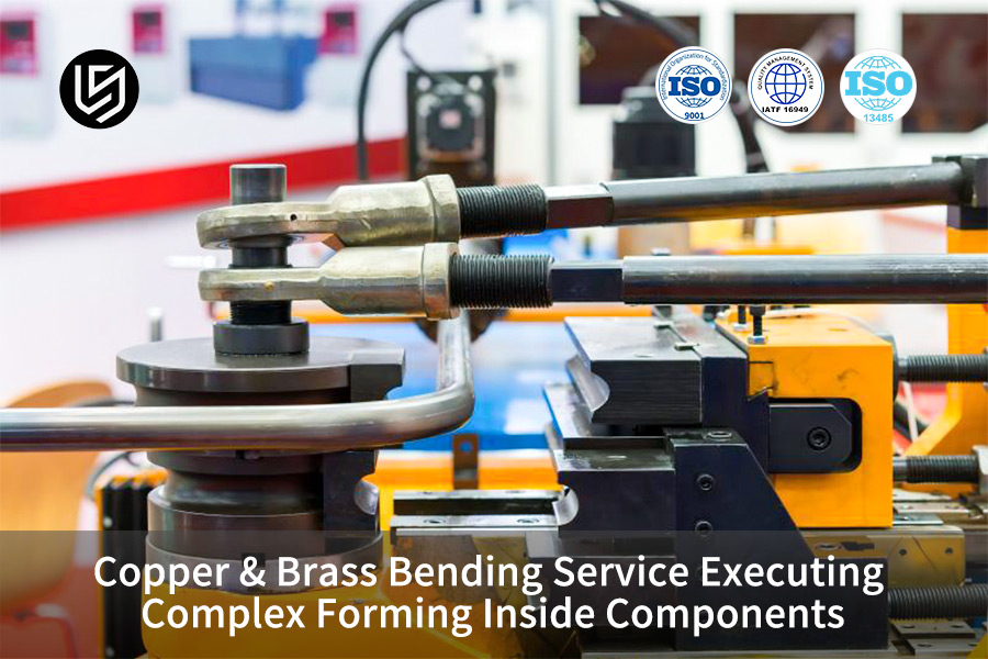
Metal bending service offers a very accurate plastic forming technique for non-ferrous metals like copper and brass. Three major challenges when bending thin-walled tubes at small radii, i.e. wrinkling, wall thickness reduction, and excessive springback tolerance in brass, are solved. Forming tolerances of 0.05mm can be reliably achieved.
Indoors, where copper busbars for new energy vehicles, medical heat exchange pipelines, and conductive hubs for industrial robots are located, the complicated forming of high purity red copper and high hardness brass has been limited by dependence on the experience with the traditional processes. The issues like inner wrinkling, outer thinning, and excessive springback tolerance at small bending radii can become factors of safety hazards, like assembly interference, overheating, and delamination. This article aims to thoroughly analyze the main process mechanisms of complex bending of copper and brass and to offer a utilization-oriented forming solution without damage to the product.
Copper & Brass Bending Service Core Process Parameters Overview
| Process Type | Applicable Material | Minimum Center Bending Radius (CLR) | Maximum Wall Thickness Reduction Rate | Dimensional Tolerance | Typical Application Scenarios |
| CNC Multi-Spherical Mandrel Rotary Bending | C11000 Red Copper (O-state) | 1.0D | ≤12% | ±0.05mm | Medical Catheters, Heat Exchange Pipelines |
| Servo Three-Point Bending | T2 Red Copper Busbar | 1.5t | ≤4% Cross-sectional Area Reduction | ±0.08mm | EV High Voltage Copper Busbar, Conductive Busbar |
| Progressive Die Continuous Forming | C36000 Lead Brass | 2.0D | ≤10% | ±0.05mm | HVAC Fittings, Pneumatic Connectors |
| Medium Frequency Annealing Composite Forming | C26800 Brass | 1.5D | ≤8% | ±0.03mm | Multi-planar Complex Structural Parts |
Key Takeaways
- Limit Wall Thickness Control: By employing multi-section fluid dynamic pressure mandrel intervention, the outer thinning rate of red copper thin-walled tubes can be strictly controlled to ≤12%. Within this range, ensure electrical and fluid safety.
- Zero-defect control: Utilizing a reverse prestress compensation algorithm and highly flexible progressive die, brass bounce is completely eliminated, stabilizing bending tolerances within ±0.05 mm.
- Efficient technical assessment: Provides a full matrix of technical parameters covering material condition and CLR, helping global high-end technology buyers and supply chain teams mitigate procurement and quality risks.
Why Trust LS Manufacturing’s Metal Bending Service For Complex Forming?
We have the capability of multiphysics simulation and precision end-to-end control system, which makes it possible to provide effective delivery of complex non-ferrous metal bending parts while greatly minimizing trial-and-error costs and quality risks.
After three months of testing and production confirmation in a North American medical ventilator copper tubing project, we found very low yield rate of less than 15% in traditional processing plant is due to the absence of pre-control of material grain deformation and real-time process compensation. Many manufacturers focus on the final dimensions only, thereby ignoring the importance of incoming material inspection and closed-loop control of process parameters.
The IATF 16949:2016 standard says that "organizations should carry out advanced quality planning for special processes, confirm process capability, and continuously monitor the process."
We follow this standard very closely and control each quality-related step throughout the entire process chain starting with incoming grain size inspection, finishing with shipment, and in between pre-forming finite element simulation, real-time servo torque monitoring during processing, and final three-axis coordinate inspection. Our equipment cluster features more than 20 closed-loop servo multi-axis CNC pipe bending machines, thereby enabling production of pipe diameters ranging from 3mm to 110mm.
If you are facing complex non-ferrous metal forming process challenges, you can submit your 3D drawings and tolerance requirements. Our engineering team will provide you with a free DFM feasibility analysis to help you identify processing risks in advance and optimize your precision metal bending forming solution.

Why Do Thin-Walled Copper Tubes Buckle During Rapid CNC Mandrel Bending Operations?
In copper bending service, the wrinkling and collapse of copper tubes is caused by tangential compressive stress exceeding the local instability limit. A multi-ball linkage mandrel made of a high-hardness, chromium-free alloy steel, together with a wrinkle-resistant auxiliary mold, exert normal support at the tangential point. This helps maintain the reduction of the outer wall thickness rate within 12% and so prevents instability.
Micromechanical Mechanism of Instability and Wrinkling
When bending tubes with very small radii, the C11000 copper bending pipe will be pushed to the limits. At a CLR less than or equal to 1.2D, and a wall thickness to outer diameter ratio (t/D) less than 5%, the material at the inside of the bend will be under very high tangential compressive stress. The dislocation of grains will become irregular as the compressive stress goes beyond the local instability limit of the material. Wrinkles happen as a result. This is also one of the top fragile conditions of thin-walled pipe fittings in custom non-ferrous bending projects.
Core Process Parameter Control Scheme
Three main parameters must be very precisely set to completely eliminate instability and wrinkling:
- Anti-wrinkle auxiliary mold installation angle: Must be strictly within 0.5°-1.5°. A very small angle will not only scratch the pipe wall but also an excessively large one will lead to loss of effective support.
- Mandrel lead time setting: Constrained within 1.5mm to 3.0mm, needing high accuracy one-to-one matching based on the pipe diameter and wall thickness.
- Mandrel ball joint configuration: For pipe diameters 10mm, a 5-ball structure is appropriate, whereas for pipe diameters <10mm, a 3-ball structure is better, for uniform support.
With a mandrel-assisted tube bending configuration that is perfectly designed, the forming stability can be hugely enhanced. The choice of different mandrel types is the main thing that affects the final accuracy and inner wall quality of precision metal bending forming.
These table shows where they are suitable:
| Mandrel Type | Applicable Pipe Diameter Range | Minimum achievable CLR | Inner Wall Roughness | Overall Cost Level |
| Multi-ball linkage mandrel | φ6mm-φ110mm | 1.0D | Ra 0.8 | Medium-high |
| Spoon-shaped mandrel | φ20mm-φ80mm | 1.5D | Ra 1.6 | Medium |
| Cork mandrel | φ10mm-φ30mm | 2.0D | Ra 3.2 | Low |
| Hydrodynamic mandrel | φ8mm-φ50mm | 0.9D | Ra 0.4 | High |
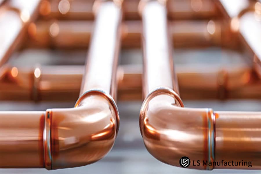
Figure 1: Precision CNC bent copper tubes with smooth 90-degree bends.
How To Calculate And Compensate For Severe Springback Variations In Half-Hard Brass Components?
In brass bending service, the problem of elastic springback of brass, which can be even 3°-7°, should be addressed with compensation based on the real-time yield strength. A rotary bending operation using the integrated tension control method is chosen. Through the application of axial tensile stress in bending, the internal and external layers of stress are equalized. So, springback is decreased to a negligible level, i.e. 0.5°.
The Material Nature of Springback
In the springback compensation bending technology system, brass alloys such as C36000 and C26800 have the characteristic of a high elastic modulus and yield strength ratio. As a piece of metal is being bent, it is both plastically and elastically deformed at the same time. After the load is taken away, the part that is elastically deformed comes back, so the effective bending angle is less than the programmed one. It is a standard technical problem that complex forming bending processes look for solutions.
Quantitative Compensation Process Scheme
We obtain the over-bending compensation formula from the dynamic finite element simulation so that springback is very accurately controlled. Main process parameters include such items as:
- Over-bending angle factor: for example, when the bending radius is 2.0D, one sets the initial over-bending angle as 1.04-1.08 times the actual target angle.
- Die Radius Hardening Treatment: The die radius radius area is hardened until it reaches hardness HRC 62.
- Segmented Delayed Pressure Holding: Hold pressure for 0.8-1.2 seconds after bending to the desired position.
This parameter system based on tension-controlled draw bending can stably cover the springback control requirements of various complex sheet metal bending parts. To obtain a complete brass springback compensation parameter table and simulation guide, contact us to receive a dedicated technical white paper to help you quickly master the core control logic of complex forming bending.
What Is The Optimal Forming Logic When Non-Ferrous Busbars Demand Precision Metal Bending Forming?
In conductive component bending cases, copper busbar bending with high-voltage calls for that the conductive cross-sectional area be preserved while at the same time no delamination is allowed at the bending radius radius. The best solution is a three-point CNC servo bending machine, which is combined with a hard polyurethane anti-indentation lower die for non-destructive forming, so that the dimensional tolerance of the bending arc transition zone can be kept within 0.08 mm consistently.
Failure Mechanism of Conductive Cross-sectional Area Loss
During the precision bending of busbars, if the bending die is not correctly designed, the material in the bending zone will be subjected to lateral shrinkage, so the local cross-sectional area will be reduced. This reduction will lead to a direct increase in contact resistance, because of this the overheated spots will be created under the load of high current and to top it off, there may even be safety hazards. This problem is a direct cause of lowering the electrical performance pass rate of the precision metal bending forming.
Key Control Points for Non-Destructive Bending
If you want to keep 100% conductivity retention, then the below-mentioned control points should be strictly followed:
- Accurate Calculation of Bending Development Coefficient: Change the K-Factor per the hardness of the material and the radius (R-angle), to control the calculation error within ±0.02.
- Die Contact Surface Coating Treatment: Micron-level Teflon coating should be applied to the bending contact surface so that the frictional resistance is reduced and also the surface scratches can be prevented.
- Forming Speed Control: Adopt a low forming speed of 15-25 mm/s so that the possibility of grain boundary dislocation and delamination caused by work hardening is minimized.
This points of control for achieving the crack-free bend forming are exactly the execution specs of the conductive parts in the metal bending service system of our company.
Why Do Rotary Draw Bending And Ram Bending Deliver Vastly Different Inner-Wall Quality For Heat Exchangers?
In the copper bonding service, the core difference between rotary bending and pressure jacking bending in pipeline processing lies in the different dynamic mechanisms for the shear force control at the bending tangent point. Rotary bending can control the rate of pipe distortion to 5% simply by fitting a pipe through both a rotating die and a clamping die at the same time that one locks the pipe and the other one locks it tightly. Then again, pressure bending without lateral constraints results in the localized collapse of very soft copper pipes as in most cases the pressure is applied locally to very small areas of the pipe surface.
Difference in mechanical principles of the two methods
In heat-exchanger tube bending applications, the rotary bending process has four constraints: a rotating die, a clamping die, a pressure die, and a mandrel. With this arrangement, the inner and outer surfaces of the bend are pushed with relatively uniform force, and the pipe wall is continuously supported throughout the bending operation. Pressure bending which is the most traditional of these methods only presses radially, thereby not providing any kind of lateral or inner wall support. This is in fact the biggest reason of the difference in performance between metal bending service approaches in the field of heat exchange piping.
The ASME B31.9 code needs that "the ovality of the bent section of pressure pipe shall not exceed 5% of the nominal outside diameter, and the inner surface shall be free of any raised or wrinkled areas that would impede fluid flow."
Our rotary bending process is perfectly compatible with this rule.
Performance Comparison of Mainstream Bending Processes
For high-pressure tube bending scenarios, the core performance comparison of three common bending processes is shown in the table below:
| Process Type | Tube Shape Distortion Rate | Maximum One-Step Forming Angle | Inner Wall Roughness | Minimum Achievable CLR | High Pressure Leakage Test Pass Rate |
| Rotary Bending | ≤5% | 180° | Ra 0.8 | 1.0D | ≥99.5% |
| Pressure Top Bending | ≥12% | 90° | Ra 3.2 | 2.5D | ≤65% |
| Roll Bending | ≤8% | 120° | Ra 1.6 | 1.8D | ≤82% |
If you would like to learn more about heat exchanger piping processing cases, please contact us to obtain a complete set of project case studies and refer to the process solutions and cost performance of similar projects.
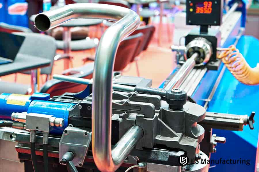
Figure 2: Stainless steel pipe secured in a rotary draw bending machine.
How To Engineer Multi-Plane Complex Forming Bending Tools To Stop Micro-Cracking In Leaded Brass Grades?
Within custom non-ferrous bending works, leaded brass is the material with the least plasticity in cold-working out of all of the metals, so it is highly vulnerable to cracking during multi-plane bending. You have to use a die core equipped with a multi-axis linkage sequential slider structure, either coupled with delayed low-speed forming (45 mm/s), or you need to carry out a 450℃-520℃ medium-frequency induction annealing process before forming.
Micro Level Reasons of Leaded Brass Cracking
In multi-plane sequential bending, lead in leaded brass like C36000 is present as free particles at grain boundaries. Under multi-directional bending stress, these lead particles act as highly stressed spots, in other words, they act as the initiation points of cracks. In multi-plane bending, different directional stresses add up, so further increasing the likelihood of microcrack formation. The risk of such a failure is very much on the rise through multi-station complex forming bending processes.
Mold and Process Collaborative Solution
By mold structure optimization and process parameter adjustment, the issue of multi-planar bending cracking in leaded brass can be solved. The main steps are:
- Mold Structure Design: Multi-axis linkage sequential sliding block mold core is employed to convert multi-planar bending into single-station step-by-step forming.
- Forming Speed Control: Forming speed is maintained at 45mm/s.
- Pre local annealing: Perform medium frequency induction annealing on the bending area, with a temperature control range of 450℃-520℃ and a temperature control accuracy of ± 5℃.
Jointly achieving leaded brass crack-free bending this solution greatly enhances the first-time forming yield of complex sheet metal bending parts. From our practical experience, we have a special workaround: When transverse micro-cracks occur at the radius (R) of the leaded brass bend, the first thing you do is analyze the forming speed. If the speed is above 50mm/s, then cutting the speed down by 30% can basically get rid of the cracks.
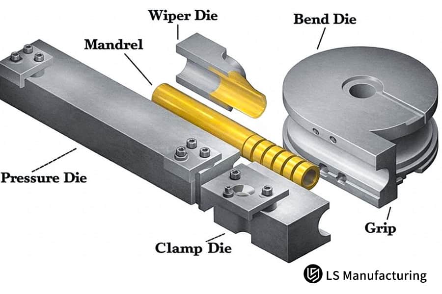
Figure 3: 3D CAD diagram of a multi-plane complex forming bending tool.
What Custom Dimple Forming Standards Apply To Ensure Zero Fluid Drag Inside HVAC Brass Fittings?
Whether partial recesses or flanging are made on brass fittings of HVAC, a smooth internal wall with no sharp corners is a must in particular when talking about brass bending services. One good option to achieve this is by using CNC ball-head servo internal extrusion forming technology wherein the extrusion die radius (R) is set more than 1.5 times the pipe wall thickness. This has a great effect in cutting down fluid resistance at the recess while also minimizing thinning.
Failures of Normal Flanging Processes
Traditional stamping flanging processes when combined with dimple extrusion bending may produce defects like edge "scratching" and non-uniform burrs along the cupped edge. Such flaws will not only raise fluid resistance but they will also act as localized stress concentration areas which in turn can give rise to stress corrosion cracking on exposure to long-term use. The fluid performance as well as the service life of precision metal bending forming will be directly impacted by these defects.
Parameter Specifications of Cold Extrusion Molding
One can find below the major component parameter specifications of CNC internal extrusion molding:
- Punch R-angle requirement: The radius of the extrusion punch's R-angle should be over 1.5 times the thickness of the tube wall.
- Die surface treatment: The surface treatment of the die is PVD coating with a hardness HV 2800 and roughness Ra 0.1.
- Extrusion speed control: Maintaining the extrusion speed at 10-20 mm/s.
Such parameter specifications have been successfully used in the large scale manufacturing of different HVAC fitting precision bending parts.
How Do Lubricity Chemistry And Multi-Axis CNC Feeds Change The Surface Integrity Of Medical Non-Ferrous Parts?
In medical-grade applications of custom non-ferrous bending, the quality of the forming of non-ferrous metal parts is influenced by lubricant chemical residues and axial feed. Setting up a water-based synthetic ester chlorine-free micro-lubrication system (MQL), together with a linear speed of 20-30 rpm and a constant clamping force controlled by a hydraulic proportional valve, can directly eliminate the possibility of mechanical scratches and chemical pitting.
Two Core Causes of Surface Defects
During the manufacturing of medical-grade tube bending, surface defects of non-ferrous metal parts mainly divide into two types: mechanical scratches, which result from feed rate mismatch and clamping force fluctuations, and chemical pitting, which takes place when electrochemical corrosion occurs due to lubricant residues. Surface quality greatly influences the standards of metal bending services delivery.
Medical-Grade Surface Quality Control Solution
We have designed an entire control solution with key parameters including:
- Motion Parameter Settings: Bending linear speed is kept steady at 20-30 rpm, and clamping force is regulated within 4.5MPa-6.0MPa through a closed-loop proportional valve.
- Lubrication System Configuring: A medical-grade water-based synthetic ester chlorine-free MQL machine is employed, which guarantees no residue and no corrosion.
- Post-Processing: Ultrasonic cleaning + passivation treatment make sure that the parts comply with the IATF 16949 cleanliness standard.
This control criterion for achieving surface-integrity control bending is also valid for copper bending service projects with stringent cleanliness requirements.
Figure 4: Worker operating a multi-axis CNC tube bender with a digital display.
Why Does Pre-Forming Heat Treatment Alter The Grain Structure And Bending Yields Of Premium Brass Alloys?
The yield of brass bending service is greatly impacted by the grain size of the annealed brass in brass bending services. Vacuum stress-relief annealing at 260℃-300℃ for 1.5-2 hours before bending effectively confines the grain size to the 15μm-35μm range, so directly elevating the bending yield to 99.8%.
Metallographic Principles of Recrystallization Annealing
Recrystallization annealing can change the proportion and distribution of the and phases in the brass alloy, meanwhile it also reduces the grain size to improve the performance of heat-treated brass bending. Studies show the more evenly distributed and suitably sized the grains are, the higher the plasticity of the mater
ial will be. Balanced grain size is the basic condition for high production in complex forming bending.
Relationship between Annealing Parameters and Yield
We tested the bending yield under different annealing parameters, and the data are shown in the table below:
| Annealing Temperature | Holding Time | Average Grain Size Range | Complex Bending Yield | Surface Orange Peel Defect Rate |
| 240°C | 1 hour | 40μm-60μm | 92.3% | 11.2% |
| 280°C | 1.5 hours | 20μm-30μm | 99.8% | 0.2% |
| 320°C | 2 hours | 5μm-15μm | 97.1% | 0.5% |
| Untreated | 0 hours | 60μm-80μm | 76.5% | 23.7% |
Heat treat control with proper precision is one of the major avenues to realize grain-size optimized bending and enhance precision metal bending forming.
Here is a very unique cost accounting formula we have come up with: Additional cost of heat treatment per unit = (equipment labor cost insulation time + energy consumption cost) / single batch loading quantity 1.15 management coefficient.
Using this, you can very accurately determine the increase in cost of the process improvement.
LS Manufacturing Breakthrough Medical Ventilator High Purity Red Copper Cold Side Multi Plane Tube Complex Forming Manufacturing Case
Client Challenge
A top-tier medical device manufacturer from North America was working on a new ventilator with high-power output. This part to be worked on was made from C11000 copper of high purity and was bent three-dimensionally using a multi-planar method in a medical catheter precision bending process. The catheter had a diameter of 12.7mm and a wall thickness of only 0.71mm. To fit the limited internal space of the device, the distance between the bending centers was reduced to 12.7mm, which means a 1.0D constant-diameter bending over-limit, and at the same time the three-dimensional spatial angular tolerance was to be 0.05mm and the inner wall roundness distortion rate 3%.
The client had contacted several traditional tube bending factories before but none of the factories succeed to make samples. The samples have shown internal wrinkles to the extent of 0.3mm, immediately bursting during a pressure test of 1.5MPa, and the yield of production was even less than 15%.
LS Manufacturing Solution
LS Manufacturing began multiphysics finite element analysis within 24 hours after we received the 3D drawings of the client to simulate the plastic strain energy distribution during bending of the copper tube.
- We initially transformed our general-purpose mold into a rotary bending master mold made from Cr12MoV alloy steel with a hardness of HRC 64, and we specially made a 5-ball linkage precision hydrodynamic multi-ball mandrel which could provide all-round support of the internal wall.
- On the springback features of C11000 cold-worked material, we implemented the servo feed system in a close loop with an adaptive springback algorithm so that automatic over-bending within 2.4°-3.1° in real-time is possible during three-dimensional directional bending.
- We opted for a lubricant that is medical-grade plant-based micro-quantity fully synthetic to maintain the coefficient of friction at μ=0.06 and get rid of the mechanical scratches.
Results and Value
To fulfill the highly demanding conditions of ultra-thin wall tube bending, the sample that was delivered finally broke new ground in performance:
- All the multi-plane spatial dimensional tolerances were kept stable within ±0.035mm.
- The reduction rate of the outer wall thickness lowered from 26% to 8.4%, and the lumen roundness distortion rate was as low as 1.8%.
- The sample was capable of withstanding the 3.0MPa ultra-high pressure airtightness test and also showed no microcracks after the destructive pressure resistance test.
Promptly, the customer wrote a contract for initial mass production of 25,000 pieces and took us along as their global core technology strategic partner.
If your project also faces similar extreme bending processing challenges, please submit detailed drawings and mass production requirements. We will customize a unique complex sheet metal bending parts solution for you and provide a precise USD quote to help your project launch quickly.

FAQs
Q1: What is the minimum centerline radius (CLR) achievable for copper and brass bending services?
It is possible to reach a minimum CLR of 1.0D for soft red copper (O-state) by using precision rotary bending dies and multi-ball mandrel technology, whereas for semi-hard brass, to prevent the outer crystal from cracking, setting a minimum CLR of 1.5D-2.0D is suggested.
Q2: How do you guarantee zero electrical cross-section reduction in conductive copper busbar bending?
The balance of lateral shrinkage of the material during the bending process is ensured for a cross-sectional area reduction rate of 4% by using a closed-loop servo three-point bending machine combined with an anti-marking rolling arc die. Based on conductivity tests conducted with a micro-ohmmeter, the results lie in the 97%-99% IACS range.
Q3: Why do LS Manufacturing brass parts exhibit no orange peel defects on custom-formed surfaces?
We enforce a thorough material receiving inspection control system in which the average grain size of red copper and brass raw materials is limited within the range of 15μm and 35μm. Before bending, a precise stress relief treatment is conducted to achieve a formed surface free from orange peel defects.
Q4: What in-line quality inspection protocols safeguard precision metal bending forming tolerances?
We set up two levels of quality barriers: besides the real-time monitoring of servo torque during processing, with immediate automatic alarms when material hardness is abnormal, all finished workpieces are subjected to a 100% inspection by an optical coordinate measuring machine and a laser scanner, this results in a factory pass rate of 99.97%.
Q5: How do you prevent microfractures during complex forming bending of leaded brass alloys like C36000?
It is a multi-station micro-step progressive forming method that we have invented, wherein the large-angle bending is split up into a series of micro-forming steps not exceeding 15° per station. Alongside internal hydraulic damping and pressure-holding technology, this method completely eliminates the possibility of microscopic tearing.
Q6: Can your copper bending service handle non-standard custom specifications and raw material profiles?
We keep a large stock of red copper and brass materials of various sizes, with pipe outer diameters ranging from 3mm to 110mm and plate and copper busbar thicknesses available from 0.5mm to 20mm.Submit your drawings to get custom solutions and accurate price quotations.
Q7: Typically, how long do you take to manufacture custom non-ferrous bending production runs?
Once the technical drawings are reviewed and approved by DFM (Design for Manufacturing) and the order is confirmed, we can complete the custom tooling design and delivery of the first batch of prototypes within 5-7 working days. For mass production batches, leveraging a fully automated production line, the standard lead time is 2-3 weeks.
Q8: Is your precision sheet metal forming in line with international regulatory standards like IATF 16949?
We have completed the certification of our factory and end-to-end quality control system by IATF 16949 and ISO 9001:2015 respectively. Besides, we are able to provide complete material certificates as well as third-party testing reports, fully meeting the RoHS and REACH standards.
Summary
Assuring quality in industrial supply chains is a fundamental business principle today. LS Manufacturing has independently created multi-physics springback finite element analysis technology, it also has an entire array of highly flexible, closed-loop servo multi-axis CNC pipe bending clusters, and its fully automated inspection process of three-dimensional coordinate measuring machine has a spatial accuracy of 0.03mm.
Be it high-conductivity EV power busbars or ultra-thin-walled intricately shaped HVAC bends capable of withstanding high-pressure pulses, we can convert complex material mechanical capability limits into effective, uniform, and cheap standardized mass production solutions, making delivery time and quality decision anxieties a thing of the past for you.
What if you are experiencing quality issues such as low sample yields from your suppliers, excessive wall thickness reduction, or surface scratches? What if you are in the process of developing multi-planar irregular-shaped bend components? There is no reason for you to spend your R&D budget on blind trial and error. Just send us your 3D CAD drawings and specific tolerances and batch requirements, our on-site engineering expert team will provide you a free, full DFM process improvement report within 12 hours Beyond a very exact mass production tiered quotation that can be used for budget auditing.
📞Tel: +86 185 6675 9667
📧Email: info@lsrpf.com
🌐Website: https://lsrpf.com/
Disclaimer
The contents of this page are for informational purposes only. LS Manufacturing services There are no representations or warranties, express or implied, as to the accuracy, completeness or validity of the information. It should not be inferred that a third-party supplier or manufacturer will provide performance parameters, geometric tolerances, specific design characteristics, material quality and type or workmanship through the LS Manufacturing network. It's the buyer's responsibility. Require parts quotation Identify specific requirements for these sections.Please contact us for more information.
LS Manufacturing Team
LS Manufacturing is an industry-leading company. Focus on custom manufacturing solutions. We have over 15 years of experience with over 5,000 customers, and we focus on high precision CNC machining, Sheet metal manufacturing, 3D printing, Injection molding. Metal stamping,and other one-stop manufacturing services.
Our factory is equipped with over 100 state-of-the-art 5-axis machining centers, ISO 9001:2015 certified. We provide fast, efficient and high-quality manufacturing solutions to customers in more than 150 countries around the world. Whether it is small volume production or large-scale customization, we can meet your needs with the fastest delivery within 24 hours. choose LS Manufacturing. This means selection efficiency, quality and professionalism.
To learn more, visit our website:www.lsrpf.com