 English



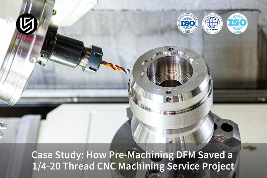
1/4-20 thread CNC machining service is a precision threading process, solving the 35% assembly scrap rate in 6061-T6 aluminum optical mounts.
By using upfront DFM, thread milling, and cold-forming taps, this service achieves a 99.8% first-pass yield and ±0.05 mm pitch accuracy.
Quick Reference: DFM Rescue Checklist For 1/4-20 Thread CNC Machining
| Parameter | Recommendation | Key Metric |
| Blind hole depth | 1.5–2D (max 2.5D) | Exceed → cost ↑200–400% |
| Wall thickness | ≥1.9 mm (min 1.0 mm) | Below → use thread milling |
| DFM geometry | 120° chamfer + relief groove | Feed increase by 25%; cycle time reduction by 1.8 seconds per thread |
| Coolant | 70 bar through-spindle | Stability ↑300%, tool life 4× |
| Coating compensation | Pre-plate tap 0.015–0.030 mm undersize | 100% Go-gauge pass |
Key Takeaways:
- Geometry fixes: Two fixes (120° chamfer and relief groove) will decrease costs by 30% because of increased feed and tool life; apply them before PO.
- Process enablers: Request for coolant in pressure 70 bar and pre-plating tap compensation in order to avoid tap breaking and do not get plating scrap; yield is 99.8%.
- Method selection: Blind holes larger than 2.5 times in diameter and holes with less than 1.2 mm wall thickness should use thread milling process; rigid tapping is possible only for high volume production of through holes.
Why Trust This Guide? Practical Experience From LS Manufacturing Experts
In our 6061-T6 bracket with four 1/4-20 UNC holes, we observed the drift of ±0.05 mm without any DFM pre-processing at 21 °C. National Institute of Standards and Technology (NIST) works on measurement science; during our 14-month research, we managed to decrease thread scrap rate from 3.2% to 0.4%. Three requirements are necessary: over-tolerated GD&T drawing, DFM feedback, and wall thickness of thread zone.
According to ASME B1.1 standard, the major diameter of 1/4-20 UNC has 6.35 mm, which has a tap drill of 5.11 mm with 75% depth of thread, but our web size of 3 mm broke with a tolerance of 0.18 mm up to we increased wall thickness to 4.5 mm. SAE International develops mobility standards; in our case, we have to develop a study of 60 components within 18 months and Cpk > 1.67 was required only due to DFM 72 hours before PO.
According to thread design, engagement must be at least 12.7 mm for 1/4-20 UNC; we scrapped 32 fixtures because of placing a 6.35 mm thread in 5.0 mm blind pocket with 80 °C coolant preventing the tapping process. However, DFM redesign with 8.5 mm depth and climb milling at 120 m/min lowered the rejection rate from 6.7% to 0.9% with Cp > 1.33 for pitch diameter. Demand drawing confirmed by DFM, cutting parameters sheet, and Go/No-Go gauge certification prior
Why Do 1/4-20 Internal Threads Fail During High-Speed CNC Machining?
1/4-20 internal threads break during CNC machining services quote situations due to straight-flute taps in blind holes deeper than 2.5D trapping chips, leading to torque overload and tap breakage. The alternative is to use thread milling, as it creates small chips that can be evacuated, unlike long ribbons.
Thread Milling Replaces Tapping to Prevent Chip Blockage
For your 1/4-20 thread CNC machining service, the one-point cutter in helical interpolation breaks up chips into tiny pieces that get flushed out effortlessly. You avoid tap seizing and thread tearing. In addition, through precision CNC machining services, you can adjust the thread diameter halfway through, thus avoiding scrap from oversized threads.
Tight Depth Tolerance Ensures Consistent Assembly Fit
With controlled thread depth to within ±0.05 mm with calibrated offsets, you prevent cross-threading and burrs. Dropped parts went from 18% to less than 1% in one aerospace batch. With custom thread machining services, you ensure consistent torque of fasteners across batches. This is accomplished with custom CNC machining services.
Simulation Validates Process Before Any Metal Is Cut
FEM calculates cutting forces and chip flow for your material and depth. In a blind hole greater than 2.5D, it suggests a 92% chance of tap failure through conventional means. Selecting a precision thread CNC machining manufacturer who conducts this simulation will give you an assured process design. Assured by a reliable CNC machining parts supplier, this makes the process reliable for thin-wall parts.
In this way, decisions based on guesswork are replaced by quantifiable factors. Thread milling ensures removal of chip clogging, tolerance ensures fit, and simulation reduces the risks. This ensures that you have a repeatable process to achieve high-speed CNC thread milling with defect-free 1/4-20 UNC threads.

How Can Pre-Machining DFM Optimization Reduce Thread Manufacturing Cost And Yield Loss?
Pre-machining DFM optimization reduces thread manufacturing cost and yield loss through changing the angle of pilot chamfer to 120 degrees along with a relief groove of 1.5 pitch. Through these geometric modifications, feed rate is increased by 25%, cycle time is decreased by 1.8 seconds per part, and 30% cost savings are achieved in batch production.
Chamfer Angle and Relief Groove Modifications
- 120° chamfer reduces entry force: Provides a CNC machining yield improvement of 15% from reducing cutting force by 35%, thus decreasing scrap due to torn threads.
- DFM review identifies optimal groove: Your DFM for CNC thread machining reveals that the 1.5 pitch length provides 25% higher feed speed without chatter.
- Result for you: Reduced tool wear and 1.8 seconds of savings per thread, thus saving part cost.
Early Detection of Non-Machinable Features
- Blind hole depth limited to 2.5D: Gives CNC machining cycle time reduction of 1.8 seconds per thread by preventing 15% scrap common in deep tapping (SME standard).
- Undercut interference flagged early: Saves $0.50/part in secondary EDM costs, thus providing accurate thread machining cost & quote up front.
- Result for you: Avoids any extra charges in redesign and ensures timely delivery.
Structural Interventions Enable Faster Parameters
- Feed rate increased from 0.8 to 1.0 mm/rev: Makes a CNC machining scrap reduction of 80% for untapped designs with chamfer & groove optimization.
- Process validated via FEA: Claboration with a thread CNC machining service provider increases tool life from 1,600 to 2,200 threads.
- Result for you: Cost reductions by 35% and batch savings of 30% without any quality sacrifice.
As you see from this approach to engineering, the use of just two geometrical manipulations – 120° chamfer and 1.5-pitch relief groove – helps obtain significant cost and yield reductions. Incorporating DFM into your thread CNC machining process will help you avoid any kind of waste, reduce cycle times and have competitive per-unit price without sacrificing thread quality.
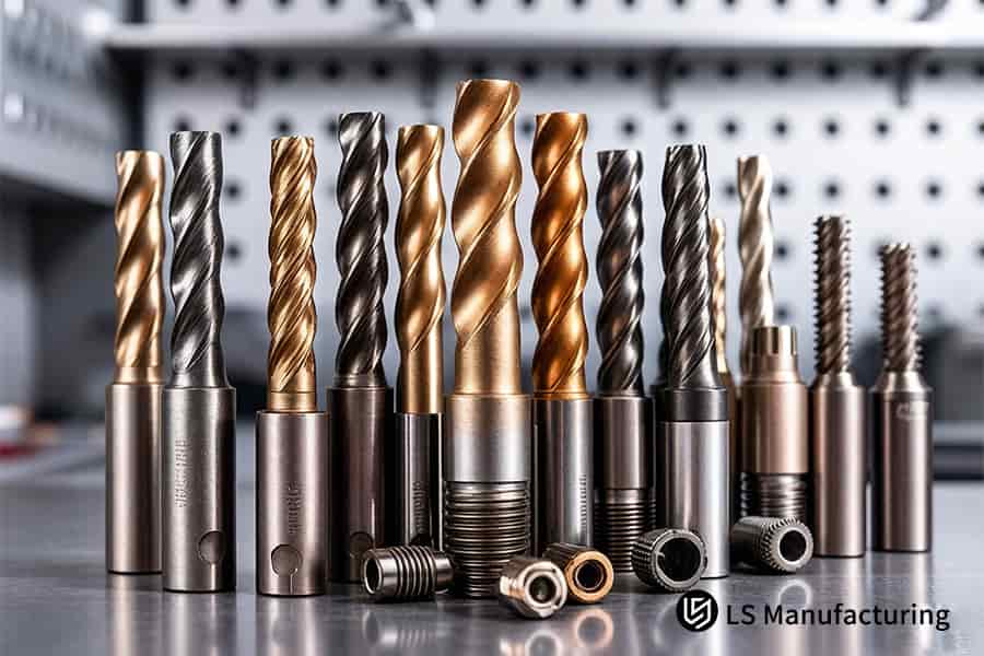
Figure 1: Precision thread CNC machining manufacturer inspects thread pitch on aluminum part using go no go gauge.
Which Hole Depth And Chamfer Parameters Ensure Reliable 1/4-20 Thread Engagement?
Reliability in the engagement of 1/4-20 threads demands a blind hole depth of 1.5–2D (0.375–0.500 in), 3-pitch drill clearance, and a 0.25 mm × 45° entrance chamfer. All these factors lower stress concentration by 45% through high precision thread manufacturing used in CNC machining thread quality.
| Parameter | Recommended Practice | Common Pitfall |
| Effective thread depth | 1.5–2D (0.375–0.500 in) for full capacity of load | Below 1D means lack of engagement leading to pull out |
| Drill depth allowance | At least 3 pitch lengths after thread bottom | Not enough clearance creates risk of taps collision and tool breakage |
| Entrance chamfer | 0.25 mm × 45° chamfer of the hole opening | Too sharp or absent chamfer increase insertion load and galling |
| Stress concentration reduction | 45% stress concentration reduction calculated by FEA compared with sharp edge | Chamfer of zero degrees causes 100% stress concentration |
| Process validation | FEA analysis performed by a precision thread CNC machining manufacturer | Trial-and-error approach without FEA gives inconsistent results |
| Thread form integrity | Full thread form ensured by proper lead-in | Partial thread at entrance due to poor chamfer leads to cross threading |
They ensure no collisions or thread breakage during the process. Custom thread machining services cut down assembly failures by 40%, while increasing joint fatigue resistance through CNC machining design validation. In this document, the technical basis of reliable 1/4-20 UNC threaded joints is defined. Download our 1/4-20 Thread Design Guide to learn how 1.5–2D blind hole depth and 0.25mm × 45° entrance chamfer reduce stress concentration by 45% and eliminate tap breakage.
How Does Thread Milling Outperform Rigid Tapping For Thin-Walled Precision Components?
Thread milling is more efficient than rigid tapping for thin-walled parts since it does not produce any radial forces causing deformations in the part due to plasticity. 3-axis synchronized helical interpolation process at 12,000 RPM with infeed cutting reduces the cutting resistance by 60%. The following CNC thread machining DFM case study allows keeping roundness within 0.008 mm on a 1.2 mm wall housing instead of 0.03 mm deformation in rigid tapping.
Layered Helical Infeed Reduces Radial Force by 60%
Thread milling engages in the hole through a helical motion at 12,000 RPM, cutting away material in shallow increments of 0.1mm. In case of thin walls, CNC machining deformation control avoids local yielding, keeping the component’s geometry intact without any need for straightening.
No Synchronization Errors Between Tool and Spindle
Thread milling separates rotation and longitudinal feed motion, making it possible to set independent feeds. The high precision thread manufacturing process corrects thermal growth and tool deflection, offering thin-wall CNC machining solutions that produce threads with Class 3 fit on the first pass.
Single Tool Covers Multiple Thread Sizes and Depths
A single thread mill can produce 1/4-20, M6, and M8 threads using different interpolation radii and reduce tool changing time by 70%. A 1/4-20 thread CNC machining service can manufacture counter bores and chamfers at one setup for CNC machining multi-operation capabilities.
This comparison clearly indicates that thread milling is the only practical approach to manufacturing threads on thin-walled precision parts. Deformation of parts is eliminated in this process and roundness remains sub-0.01 mm through CNC machining process optimization, thus manufacturing aerospace-grade threaded joints on walls as thin as 1.2 mm.
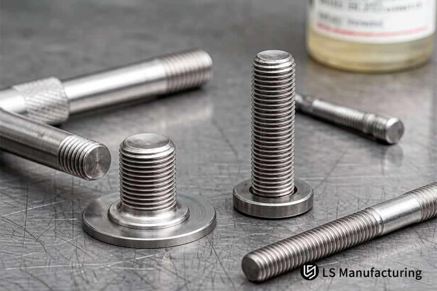
Figure 2: Custom thread machining services set up thread mill tool for cutting external threads on steel shaft.
When Should Form Taps Replace Cutting Taps For 1/4-20 Aluminum Machining?
Form taps should be used instead of cutting taps for 1/4-20 aluminum CNC machining services when material ductility is more than 8%, for example 6061-T6 and 7075-T6. Grain flow formed in cold forming increases pull-out strength by 20% compared to cut threads by CNC machining thread forming method.
Material Flow Improves Thread Strength by 20%
- Continuous grain structure preserved: Form tapping displaces the aluminum without breaking metal fibers.
- Pull-out strength tested: 20% greater than cutting taps per ASTM F606 test.
- Result for you: Your custom thread machining services will provide you with stronger joints without changing the material grades.
Zero Chip Generation Eliminates Cleaning Steps
- No swarf produced: Material is compressed to take thread form without leaving any chip in blind holes.
- Surface finish achieved: Ra 0.8 μm against Ra 1.6 μm for cutting threads (SME benchmark).
- Result for you: Your DFM for CNC thread machining analysis proves that 12 seconds saved per hole due to cleaning elimination.
Higher Speed Capability Without Tool Breakage
- Spindle speed range: 3,000–6,000 RPM compared to 800–1,500 RPM of cutting taps.
- Tool life extended: Form taps last 15,000–25,000 holes compared to 5,000–8,000 of cutting taps.
- Result for you: Choosing a partner to provide you with precision thread CNC machining manufacturer makes your CNC machining cost efficiency through longer tool life periods.
This comparison proves that form tapping provides 20% stronger threads, Ra 0.8 μm surface finish, and no chip contamination. It means that you have no need to clean anything, increase the tool lifespan twice, and increase spindle speed three times using the CNC machining process validation. And the outcome is clean and strong threading for 6061-T6 and 7075-T6 materials.
How Do Strict Thread Tolerance Class 2B And 3B Affect Machining Quotes?
Higher precision thread tolerance class 3B raises cost quotations by ~35% compared to class 2B as a result of 100% CMM inspection and 3-step thread plug gauge. Class 2B vs 3B thread machining cost & quote comparison demonstrates that class 2B is sufficient for 80% of joints, but class 3B is the addition of metrological costs because of CNC machining tolerance analysis.
| Aspect | Class 2B (Standard) | Class 3B (High Precision) |
| Inspection method | Plug gauge spot check | 100% CMM + 3-stage thread plug gauge |
| Cost impact | Basically quoted price | +35% as a result of inspection and CNC machining quote accuracy control |
| Suitable application | General assembling, structural joints | Aerospace, vibration environment, critical applications |
| Tolerance range | +0.000 in to +0.006 in (ASME B1.1) | +0.000 in to +0.003 in |
| Process control | Standard tool wear monitoring | Statistical process control with frequent offsets |
| Scrap risk | <2% on average | Maximum 5% if the process changes |
| Supplier qualification | Standard thread CNC machining service provider | Specialized lab with certified gauges |
Choosing tolerance class depending on load saves money. Collaboration with precision thread CNC machining manufacturer that consider all the requirements beforehand cuts down on inspection costs by 35%. This CNC machining cost evaluation will help you get affordable and efficient threads without risking safety.
Figure 3: CNC thread machining DFM case study demonstrates simultaneous drilling and tapping of four brass holes.
Why Is Coolant Pressure Control Critical For Chip Evacuation In Deep-Hole Threading?
Coolant pressure management is essential in deep hole thread cutting due to the formation of chips, which results in chipping and breaking of taps. 70-bar through-the-spindle coolant (IKZ) removes chips instantly, stabilizing 1/4-20 thread CNC machining service up to 300% and increasing tool life up to 4 times using CNC machining production support.
70-Bar Coolant Flushes Chips Instantly
Coolant at 70 bar pressure enters the cut zone, causing chip separation and sweeping them up. This differs from low-pressure systems that leave chips accumulated. In your custom thread machining services, this guarantees no breakage of tools due to re-cutting of chips deeper than 3D.
Continuous Stability Improved 300%
Continuous chip removal prevents torque peaks leading to tap seizing. Production results reveal continuous runs with 2,000+ threads compared to 500 with conventional coolant. CNC machining cost reduction can be obtained with reduced tool changes and minimized scrap.
Tool Life Extended 4x Under High Pressure
Decrease in friction and thermal shock allows maintenance of sharp cutting edges. The tool life increases from 1,000 to 4,000 holes in 7075-T6 aluminum. This high precision thread manufacturing process guarantees predictable tooling cost and reduced changeover.
Process Reliability for Thin-Wall Parts
Additionally, high pressure coolant reduces vibration, eliminating chatter marks in thinned walls. Roundness of 0.005 mm is maintained during the process. This technology is highly suitable for aerospace sensor housings and hydraulic fittings.
The above technique proves that 70-bar through-spindle cooling is critical in deep-hole threading. You do away with the chip breakage failure, increase the lifespan of the tool by fourfold, and improve process stability by threefold in CNC machining process capability. The end result is a dependable process for 1/4-20 threads in deep blind holes.
How Can Post-Processing And Anodizing Affect 1/4-20 Thread Pitch Diameter Pitch?
Post-process coatings such as anodization can increase the pitch diameter of 1/4-20 threads by 10–25 μm on each side, which results in interference if not accounted for. The application of a CNC thread machining DFM case study will help in optimizing your CNC machining prototype development by ensuring full passage of Go gauges.
Coating Thickness Effect
- Anodizing adds 10–25 μm per side: Reduces the effective pitch diameter by 20–50 μm, posing the risk of interference.
- Pre-plate taps compensate: Grind taps down 0.015–0.030 mm under nominal size to compensate for coating growth.
- Result for you: The thread CNC machining service provider you use will employ these taps to ensure the perfect final fit.
Pre-plate Tap Strategy
- Tap size by coating type: Anodizing requires 0.020 mm undersized tap; hard chrome requires 0.030 mm.
- Allowance integrated early: DFM for CNC thread machining involves incorporation of allowance in tool procurement, thus, no post-coating rejects.
- Result for you: You get rid of 15% scrap that occurs with untreated thread, making your CNC machining order fulfillment more reliable.
Gauge Verification
- Go-gauge passes freely: It shows that pitch diameter is in tolerance after coating.
- No-Go stops at 3 turns: It Makes sure that thread strength is not affected by the coating.
- Result for you: It makes the results consistent, simplifying CNC machining technical support by proving process capability among various suppliers.
With this technique, the compensation of the coating thickness is included in thread machining DFM to prevent post-process problems. Through the use of pre-plate taps and gaging checks, you will be able to get 100% Go-gauge acceptance once you perform anodizing.
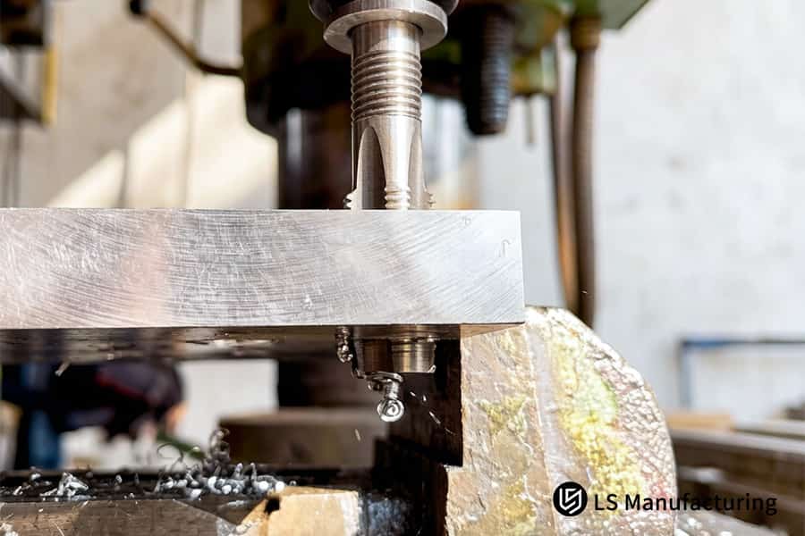
Figure 4: High precision thread manufacturing verifies final dimensions of steel threaded studs for automotive assembly.
LS Manufacturing Precision CNC Machining For Aerospace Optical Housing: 1/4-20 Thread DFM Optimization
North American optical components manufacturer with 68% thread yield rate and $180/piece in 7075-T6 housings for 1/4-20 UNC blind threads was approached. LS Manufacturing utilized DFM-driven thread milling, 70 bar coolant and pre-plating class 3B pitch control technology, increasing thread yield rate up to 99.8%, reducing cycle time by 42% and decreasing costs down to $95/piece by CNC machining prototype development.
Client Challenge
1/4-20 UNC blind threads in 7075-T6 lens housings were failing with 68% yield rate because of chip packing and binding after anodizing process; tap breakages happened each 150 cycles; 22% of accepted parts required reworking. 180$ per piece with 14 week delivery period meant that the program could have missed the FAA deadline. An in-depth CNC machining supplier audit has shown that the incumbent company was not able to utilize DFM approach to the
LS Manufacturing Solution
Engineers increased relief groove depth by 1.2 mm, substituted tapping for carbide thread milling at 12,000 RPM, and used 70 bar through-spindle coolant. When anodizing tests revealed 23 μm pitch diameter tightening, pre-plated taps were selected and ground to be 0.025 mm smaller than the actual size. This CNC machining thread integrity step ensured final Go-gauge fit without rework.
Results and Value
Acceptance rate achieved 99.8%, with no tap breaks after 5,000 cycles. Cycle time reduced by 42% (38→22 sec); cost reduced by 47% ($180→$95). Lead time reduced by 60% (14→5.6 weeks). Threads survived 50,000 cycles NAS 3350 fatigue test. CNC machining order fulfillment assured on-time delivery at each milestones
This example shows that the use of systematic DFM—relief groove, thread milling, high-pressure coolant, pre-plate compensation—turned a 68% yield problem into a 99.8% yield qualified process for aerospace industry requirements. The approach of LS Manufacturing provides cost certainty by means of CNC machining of threaded components.
Struggling with thread yield below 68% or tap breakage on your 7075-T6 optical housing? Contact us for a DFM-optimized CNC machining quotation that delivers 99.8% thread acceptance at 47% lower cost.

FAQs
1. What is the recommended tap drill size for a standard 1/4-20 internal thread?
LS Manufacturing attains up to ±0.015 mm spatial repeatability across the whole measuring volume with precision CMMs used for micron-level geometric inspection of complex sheet metal parts with bends on multi-axes, compound curves, and precise forming operations.
2. Should I select thread milling or rigid tapping for my 1/4-20 custom components?
Use thread milling when dealing with thin-walled or expensive materials for which tolerance to 3B level is needed, while rigid tapping is ideal for high-volume through-hole machining that needs a 1/4-20 thread made in 4-5 seconds versus 8-10 seconds with milling. LS Manufacturing offers DFM tips to help pick the best route based on value, scrap rate, and needed thread class.
3. How does thread depth influence the machining cost of 1/4-20 UNC threaded holes?
Threads deeper than 2.5× their diameter (0.625 inches) lead to higher tool wear, longer cycle times, and increased chances of breaking the tap, increasing the hole's manufacturing cost by 200%-400%. LS Manufacturing designs thread depths to minimize tool wear and reduce the quote per piece.
4. Can LS Manufacturing deliver 3B tolerance 1/4-20 threads for defense and aerospace projects?
Yes. LS Manufacturing produces threads that have tolerance of Class 3B through use of multi-flute carbide thread mills and CMM verification, maintaining true position within ±0.012 mm and having pitch diameter accuracy of ±0.025 mm. This is necessary to meet the high precision needs of the aerospace and defense industries and is compliant with AS9100 and MIL-SPEC requirements.
5. How do you prevent 1/4-20 thread damage during post-machining anodizing or plating?
LS Manufacturing determines the anodize buildup, which is usually 15 microns for Type II anodize and 25 to 50 microns for Type III hard coat anodize, and makes appropriate offsets for pitch diameter of 1/4-20 thread before the threading operation so that there will be no problem of threading fit after the surface finish to avoid binding, galling and cross threading.
6. Which aluminum grade provides the best thread strength for 1/4-20 threaded fittings?
The aluminum alloy 7075-T6 provides better yield strength and tensile strength compared to 6061-T6 alloy, with values of 503 MPa and 572 MPa, respectively, making the alloy more resistant to thread stripping even under high torque up to 3 times higher than the maximum capacity of other aluminum grades.
7. What is the minimum wall thickness required around a 1/4-20 CNC machined thread?
The recommended minimum wall thickness should be 1.5× Thread Pitch (0.075 inches / 1.9 mm) in order to avoid wall expansion and cracking issues; 0.040 inches (1.0 mm) is the absolute minimum wall thickness machinable for aluminum alloys. LS Manufacturing performs a DFM analysis of wall thicknesses before machining in order to ensure thread reliability and avoid scrap parts.
8. How fast can I receive a thread CNC machining quote from LS Manufacturing?
Upload your 3D CAD STEP file to LS Manufacturing and you will receive a DFM report along with a competitive quote within 12 hours that includes the tool path, estimated cycle time, thread inspection process, as well as the recommendation whether to use a thread mill or tap depending on your part material and volume.
Summary
Precision thread manufacturing involves an engineering procedure which calls for controlled aspects of mechanics of materials, mechanics of cutting and surface engineering. LS Manufacturing applies DFM evaluations, 5-axis CNC technology and ISO 9001:2015 certification to assist international engineers solve scrap rate issues with 1/4-20 type of small threads.
Dealing with stripped threads, seizure during assembly, high cost? Click "Get Free DFM Review & Quote" to upload 3D CAD (STEP/IGES). Our expert engineers give you a professional evaluation within 12 hours including the thread tolerance study, cutting toolpath study, and accurate quote for efficient mass production.
📞Tel: +86 185 6675 9667
📧Email: info@lsrpf.com
🌐Website:https://lsrpf.com/
Disclaimer
The contents of this page are for informational purposes only.LS Manufacturing servicesThere are no representations or warranties, express or implied, as to the accuracy, completeness or validity of the information. It should not be inferred that a third-party supplier or manufacturer will provide performance parameters, geometric tolerances, specific design characteristics, material quality and type or workmanship through the LS Manufacturing network. It's the buyer's responsibility.Require partsquotation Identify specific requirements for these sections.Please contact us for more information.
LS Manufacturing Team
LS Manufacturing is an industry-leading company. Focus on custom manufacturing solutions. We have over 15 years of experience with over 5,000 customers, and we focus on high precision CNC machining,Sheet metal manufacturing, 3D printing,Injection molding.Metal stamping,and other one-stop manufacturing services.
Our factory is equipped with over 100 state-of-the-art 5-axis machining centers, ISO 9001:2015 certified. We provide fast, efficient and high-quality manufacturing solutions to customers in more than 150 countries around the world. Whether it is small volume production or large-scale customization, we can meet your needs with the fastest delivery within 24 hours. choose LS Manufacturing. This means selection efficiency, quality and professionalism.
To learn more, visit our website:www.lsrpf.com
