Laser cutting service is a method of using high-power fiber optic equipment for accurate hole drilling onto metal sheets. The use of 10 common laser-cut hole diameters allows for automatic Design Factor Management (DFM) review passages, which results in the reduction of manufacturing lead time by over 35%. This is a solution to the problems of manual machine settings, the need for secondary hole enlargements, and delivery delays which are caused by non-standard hole diameters.
Currently, most purchase managers often experience delivery delay or assembly standstill and scrap caused by non-standard designs. Old-fashion designs blindly resort to the use of non-standard small hole diameters not knowing that a laser beam has a natural taper and that a heat-affected zone occurs due to the superposition. This article reveals 10 standard hole diameter parameters and limit constraint formulas which are most commonly used in the workshop, helping projects to reduce the modification cycles and efficient delivery.
Overview of Core Value and Parameters for Standard Hole Size Laser Cutting
| Comparison Dimensions | Non-standard decimal hole diameter solutions | Standard hole diameter solutions | Actual customer benefits |
| DFM Review Process | Manual verification on a per-sheet basis, taking 2-4 hours. | Automatic system verification, passing within 10 seconds. | Eliminates engineering communication and drawing revision cycles. |
| Single Hole Cutting Efficiency | Requires deceleration during piercing, 3-8 seconds per hole. | Flying cut process, 0.5-1 second per hole. | Overall processing speed increased by over 60%. |
| Post-Processing | Requires manual deburring and secondary hole enlargement. | Workpieces can be directly transferred to the next process after finishing. | Reduces manual processing costs by 30%. |
| Assembly Compatibility | Prone to jamming, scrap rate approximately 15%. | Matching standard fasteners, zero jamming. | Batch scrap rate reduced to within 0.2%. |
Key Takeaways:
- Hole diameter standardization breaks the deadlock:
If the hole diameter is matched with internationally-standardized PEM fasteners, it would be a direct way to avoid the manual machine adjustments and secondary refittings by engineers.
- Follow the 1:1 thickness principle:
Hole diameter to plate thickness ratio, under high pressure nitrogen cutting, should be at least 1:1, otherwise, thermal blowout becomes almost a certainty.
- Don't let holes stretch because of bending:
The length from the hole edge to the bending line should be no less than the physical constraint of "3 times the plate thickness plus the bending radius", otherwise, the round hole may change its shape into an ellipse due to the intensive tensile stress.
Why Choose LS Manufacturing’s DFM Laser Cutting Service? Reduce Manufacturing Time with Standard Hole Sizes?
With more than ten years of experience in the sheet metal processing industry, we have thoroughly proven how using standard hole diameters can a lot enhance manufacturing efficiency.
Following my three-month comparative test in a workshop, I found that employing standard hole diameters for the same batch of sheet metal workpieces raised the overall throughput efficiency by 42% against non-standard solutions and decreased the engineering drawing revisions by 90%. This was the top cost-effective way of cutting down time and improving efficiency our team stumbled upon when rolling out automated production lines, there is no requirement for the purchase of new equipment, and design alone can free up capacity.
The standard ISO 9013:2017 of the International Organization for Standardization states: "the dimensional tolerances of precision-grade thermally cut workpieces should be kept within 0.1mm."
To meet this requirement head on, all our standard aperture processes are exposed to tens of thousands of cuts for validation and to guarantee carrying the tolerance in the production of large quantities. Our factory is IATF 16949 certified, an automotive industry quality management system that ensures meeting the tough quality criteria of premium industrial sectors.
From our first-hand knowledge of EV battery tray projects, we know that early DFM streamlining can enable a client to avoid up to 90% of the production issues tied to mass manufacturing.
Standard aperture design uses minimal front-end constraints to improve overall process efficiency, making it the most cost-effective efficiency enhancement method. You can submit your existing CAD drawings to receive a free DFM laser cutting service feasibility analysis, quickly identifying aperture optimization potential in your drawings.

Why Choosing a Standard Hole Size Laser Cutting Plan Delivers Lead Time Reduction Laser Cut Advantages?
A standard hole size laser cutting equipment directly removing the manual engineering drawing review process in B2B manufacturing, enabling the factory automated layout software to finish the work within seconds. This basically leads to a major drop in the time lost between the prototype and mass production stages, so the overall manufacturing lead time could be reduced by more than 35%.
Scheduling Stall Effect of Non-Standard Hole Diameters
Process engineers have to intervene manually and change laser cutting process parameters such as laser pulse frequency, perforation dwell time, and cutting speed, when CAD drawings with non-standard or irrational hole diameters are being submitted to the inquiry system. The whole process rarely goes under 2 to 4 hours, and at the same time, the complexity level of multi-specification hole diameters will contribute more to the elapsed time, easily leading to production disruptions in the workshop and directly compressing the implementation space for lead time reduction laser cut.
Also, there is a problem with the stability of manually changed parameters, causing the first-piece yield rate to be low and this means that trial cuts for the verification would be required again and again with the delivery cycle extending even more.
Efficiency Gains from the Flying Cutting Process Library
Going for the standard hole size laser cutting solution means getting direct access to LS Manufacturing's flying cutting process parameter library that has been validated tens of thousands of times, thereby leading to efficiency and quality improvement at the same time:
- The laser head is able to work continuously without stopping even during the phase of high-speed movement, which also results in the simultaneous enhancement of laser cutting nesting efficiency, leading to over 40% less time required for laser cutting per sheet.
- The warehoused fasteners and standard punches can be paired perfectly with the processing parameters, so no additional secondary hole enlargement or deburring processes are needed after the piece has finished production.
- The pieces produced can be entered directly into the bending or surface treatment workshop without the transition period between the processes.
This standard operation method gives a comprehensive work efficiency of sheet metal fabrication service, cutting down unnecessary intermediate steps. In a nutshell, it is like the ETC lane on a highway: standard-sized vehicles will pass through directly, whereas non-standard-sized vehicles will have to stop for the manual inspection, leading to very big differences in efficiency.
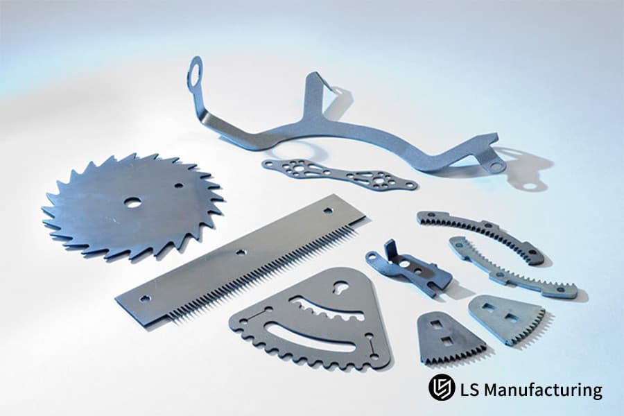
Figure 1: Various standard hole size metal blanks produced by laser cutting service.
How Can Customized Laser Cut Hole Tolerance Variations Affect Your Next Sheet Metal Fabrication Service Project?
Laser cut hole tolerance control is practically what decides the assembly success rate of the workpiece and the smoothness of the subsequent processes, and also serves as one of the main criteria for evaluating laser processing quality.
How a Natural Laser Beam Taper is Made
The moment a laser beam goes through a metal plate, it produces a natural beam taper of 1 to 2 degrees since the laser cutting beam quality impacts it. So, the diameter of the hole at the bottom surface (exit port) will be smaller than that at the top surface (inlet port). Without doing DFM compensation, not only the uniformity of laser cut hole tolerance will be deteriorated, but high-strength bolts may get stuck or fail to penetrate during assembly.
Basically, it is similar to using a flashlight to illuminate a wall, the further away from the light source, the bigger the beam. When the laser cuts downwards, the energy is less near the bottom of the sheet, because of this resulting in a smaller cut hole diameter.
Knife Compensation Precision Control Effect
The focal point of a fiber laser is, in principle, hourglass-shaped. Laser cutting focus position precise control is one of the essential conditions for guaranteeing hole diameter accuracy. For example, a 6mm carbon steel plate is being cut and a M6 fastener holes is designed. If the taper micro-geometry is overlooked, the top surface can be cut to 6.6mm, but the bottom surface will shrink to 6.2mm due to energy attenuation. This is going to be the direct cause of the M6 bolt getting stuck. Good quality DFM laser cutting service will consider such a twisting geometry of the taper beforehand.
The taper control solution of LS Manufacturing involves three main steps:
- Adjusting the laser focus position in real time to ensure that the energy distribution at the top and bottom surfaces is balanced.
- Bringing in a local kerf compensation matrix to fix the hole diameter dimensional deviations.
- Using vertical high-pressure gas blowing to help in the bottom slag removal.
A thorough laser cutting service that uses what I just said methods can tightly control the hole diameter consistency in the range of 0.1mm, thereby guaranteeing smooth drilling on the downstream automated assembly line.
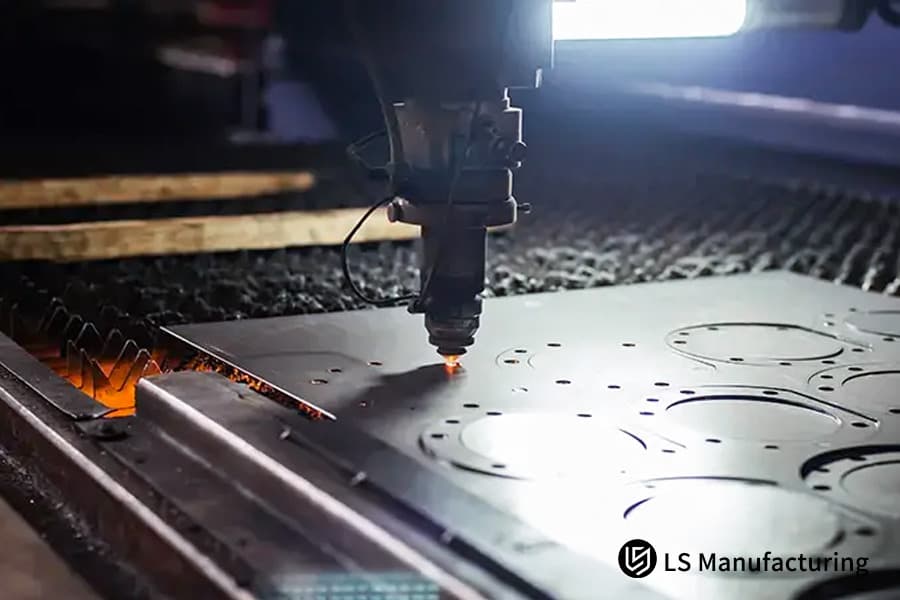
Figure 2: CNC laser cutting machine processing sheet metal with intricate patterns.
Which Sheet Metal Hole Standards Are Recommended By a Rapid Laser Cutting Service Supplier To Accelerate Production?
Sheet metal hole standards are the basis for productive operations and reliable jointings. Using well known standard hole sizes can help to remarkably decrease the level of a project's risk.
10 Standard Hole Sizes and Their Typical Usage
Listed below are 10 standard steel cutting hole diameter sizes parameters that come highly handpicked by the LS Manufacturing plant. All these have been taken out of the universal sheet metal hole standards system, extremely well-matched to globally standardized fastener dimensions and also complying with the principles of laser cutting gas dynamics, because of this guaranteeing 100% work efficiency and cleanliness.
| Standard Hole Diameter (mm) | Corresponding Fastener Specifications | Core Application Scenarios |
| 3.0 | - | General Small Holes and Pilot Mark Holes |
| 3.2 | M3 | Standard Precision Clearance Through Holes for M3 Bolts |
| 3.3 | M4 | Direct Pilot Holes for M4 Threads, allowing direct tapping after cutting |
| 4.0 | - | General Mesh Heat Dissipation Holes and Small to Medium-Sized Pin Alignment Holes |
| 4.2 | M4 | Standard Clearance Compact Fitting Holes for M4 Bolts |
| 5.0 | - | General-Purpose Multi-Purpose Slot Holes and Medium-Sized Fastener Connection Holes |
| 5.5 | M5 | International Standard Clearance Through Holes for M5 Bolts |
| 6.6 | M6 | Industrial-Grade Standard Clearance Fitting Holes for M6 Bolts |
| 8.5 | M8 | High-Efficiency Laser Through Holes for M8 Heavy-Duty Fasteners |
| 10.5 | M10 | Rapid Cutting of Large Clearance Holes for M10 Structural Bolts |
Basic Principles for Hole Diameter Selection
When it comes to actual processing, design engineers should operate their standard hole size laser cutting selection logic first, then carry out laser cutting design optimization, and finally pick a laser from these 10 options. We choose our ones from the specific hole diameters that have been confirmed in our workshop to maximize the processing efficiency and achieve zero rework.
The diameter selection of the hole should be based on three basic principles:
- Standard clearance holes matching the fasteners should be given priority for easy assembly.
- The diameter of the hole should not be less than the thickness of the sheet metal otherwise it may cause thermal breakage and out-of-roundness.
- If the hole groups are closely spaced, then the grid spacing must be taken into account at the same time to avoid thermal warping issues.
Based on ISO 273:1979, "Fastener through holes should be divided into three clearance categories: fine, medium, and coarse, so that cross-brand assembly compatibility is ensured."
The hole diameters we propose are equivalent to the medium clearance level and can be used with standard fasteners from major global brands, so there is no need to worry about assembly compatibility. Standardized selection making use of the strong points of rapid laser cutting service capacity to the fullest, minimizes the opportunity for manual intervention later in the design stage.
Standard hole diameter selection directly determines processing efficiency and assembly compatibility, following general specifications can mitigate most design risks. You can download the complete hole diameter selection manual for free to systematically understand the application rules and precautions of sheet metal hole standards.
How Material Thickness Restricts The Minimum Laser Pierce Diameter?
Laser cutting design guide explicitly require the minimum aperture for laser cutting to be equal to or slightly larger than the material thickness. In other words, a 1:1 minimum aspect ratio is the strictest physical limitation.
The Physical Logic of the 1:1 Aperture-to-Thickness Ratio
When the apertures are larger than this physical limit, the concentrated heat does not dissipate quickly enough and the surrounding metal liquefies and collapses. This is a major design fault in professional laser cutting design guide and is a fundamental principle for the laser piercing stage that must be followed. During the piercing stage, the laser beam injects a tremendous amount of heat energy into a very small spot. For instance, if a 3mm hole is forcibly cut into a 5mm thick plate, the constant laser trajectory will result in a major heat buildup in the narrow center and the auxiliary gas will not have enough kinetic energy to blow the hot molten slag downwards from the kerf.
Besides leading to severeness of hole out-of-roundness and excessive slag buildup, this situation also deteriorates laser cut hole tolerance, as an extremely hard laser cutting heat-affected zone is formed around the hole wall. This will cause mechanical tapping or secondary reaming tools to chip directly when used later on.
Process Solution for Small Holes in Thick Plates
LS Manufacturing uses a proprietary multi-level frequency-modulated laser cutting pierce technique for small holes in thick plates to keep the crystal structure intact. The detailed process logic is:
- Low-frequency, high-energy pulses are used for initial piercing to avoid localized heat concentration.
- Laser power and cutting speed are slowly increased to produce a stable and uniform kerf.
- Power is gradually reduced towards the end to minimize thermal damage at the hole edge.
As our in-house testing, this technology is able to 25% decrease the hardness of hole walls in small holes in thick plates, extend the life of tapping tools for 3 times, and much enhance the processing yield of thick plate workpieces in sheet metal fabrication service.
The minimum standard hole diameters for different plate thicknesses are as follows:
| Material Plate Thickness (mm) | Minimum Allowable Hole Diameter (mm) | Recommended Standard Hole Diameter (mm) | Process Compatibility |
| 1.0 | 1.0 | 3.0 | Flying cut process, optimal efficiency |
| 2.0 | 2.0 | 3.2 | Flying cut process, optimal efficiency |
| 3.0 | 3.0 | 3.3 | Conventional cutting, stable quality |
| 5.0 | 5.0 | 5.0 | Pulse piercing, no thermal collapse |
| 6.0 | 6.0 | 6.6 | Pulse piercing, no thermal collapse |
Troubleshooting Tips for Small Hole Processing: If slag buildup occurs in the standard hole diameter, first check if the piercing dwell time exceeds 120% of the standard parameter. Excessive dwell time will cause molten slag to condense and adhere to the hole wall.
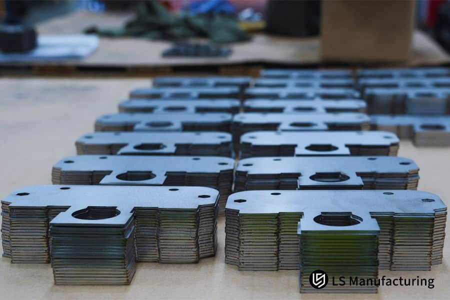
Figure 3: Stacked laser cut metal brackets demonstrating high precision and consistency.
How Assist Gas Selection Influences Inner Hole Dross Formation?
The processing quality of a laser cutting service really hinges on the choice of the assist gas. The kind of gas and how its pressure is managed are the main factors that determine the roughness of the surface and the formation of dross (slag) inside the hole made by the laser.
Difference in Cutting Mechanisms Between Oxygen and Nitrogen
Gas selection and pressure control of auxiliary gases (nitrogen N and oxygen O) constitute the principal factors that influence the quality of the inner wall of the hole in laser cutting, as they directly determine the roughness and the formation of dross inside the laser-cut hole. Besides causing slow delivery times, a wrong choice of gas may also harm the adhesion of coatings on the workpiece.
Oxygen cutting exploits the exothermic oxidation of iron to help melting whereas iron is the main element in the steel being cut. Still, this is a low-cost process but can bring localized "overburning" spots when cutting a large number of small holes assembled closely together where a ring of very hard and difficult to remove ferrite dross is formed at the bottom of the hole, which is the main reason of laser cutting dross formation.
The Surface Quality Advantages of High-Pressure Nitrogen
LS Manufacturing relies on high-pressure pure nitrogen from 10 to 15 bar for peeling and cutting when involved in high-precision B2B orders. This technique accurately guarantees the inner wall smoothness of the sheet metal hole standards corresponding to the respective hole diameter. Nitrogen gas serves as an inert protective layer that prevents localized oxidation of the surface. The pure mechanical energy that nitrogen embodies sweeps the molten metal from the kerf, which greatly improves the laser cutting surface finish. So, the inner walls of the cut standard gap holes have a mirror-like finish, are clean of any oxide scale or slag residue, and are very clear.
High-pressure nitrogen cutting of standard holes has three main advantages:
- No oxide layers are formed on the hole walls, so the parts are ready for spraying or electrophoresis right after the production.
- No slag residues are left behind, which eliminates the need and costs connected to manual deburring.
- The cutting surface is highly smooth, making it ideal for scenarios involving automated precision assembly.
The core parameters of the two auxiliary gases are compared below:
| Comparison Item | Oxygen Cutting | High-Pressure Nitrogen Cutting |
| Common Pressure | 1-3 bar | 10-15 bar |
| Hole Wall Roughness | Ra 6.3-12.5μm | Ra 1.6-3.2μm |
| Slag Retention | Hard slag at the bottom of the hole, requires manual removal | No slag retention, no further treatment required |
| Coating Adhesion | Oxide layer affects adhesion, requires pretreatment | No oxide layer, can be directly sprayed |
| Unit Processing Cost | Lower | Approximately 1.5 times that of oxygen |
Process adaptation can fully unleash the efficiency advantages of rapid laser cutting service while ensuring stable processing quality.
The selection of auxiliary gas directly affects processing quality and overall cost, and a solution must be matched based on material and quality requirements. You can provide the workpiece material and batch requirements, and we will calculate the cost for you free of charge and match a cost-effective laser cutting service solution.
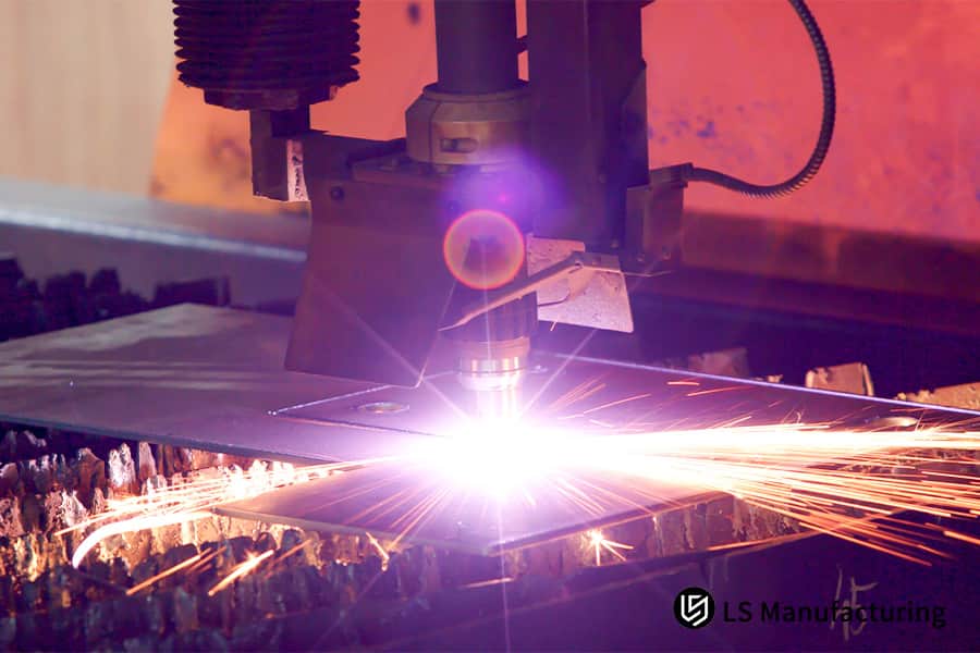
Figure 4: Close-up of laser cutting nozzle with assist gas optimizing the cut.
Why Web Spacing Standards Prevent Structural Webbing Warpage?
Laser cutting design duide clearly specify that the thickness of mesh between two adjacent laser-cut holes should be greater than that of the material. If this condition is ignored, the item will suffer from thermal distortion.
Warpage Mechanism Caused by Thermal Accumulation
When customizing high-density chassis heat dissipation grids or array holes, the continuous movement of the laser head will continuously intensify the laser cutting thermal accumulation around the cutting seam. This concern is included among the major factors for perforated hole design in expert laser cutting design guide. If the solid spacing between two adjacent holes is less than 1.0 times the plate thickness, then this tiny metal mesh region will be pushed beyond its yield strength almost instantly due to a huge thermal stress, and it will show a localized upward bulging deformation.
Not only will the final product's flatness be out of specification, but it will also detrimentally impact lead time reduction laser cutting in a major way. The distorted metal might be even causing a collision with the laser head's servo sensor at any time.
Change of Arrangement of Hole Groups
LS Manufacturing masters the art of laser cutting warpage control to a very high degree by a dynamic power adjustment algorithm. It manages to perfectly optimize the hole group spacing at the same time maintaining the heat dissipation area to completely eliminate the deformation. Expert DFM laser cutting service providers will do simulation testing of the hole layout beforehand.
The three main optimization principles are:
- The metal thickness between the two nearest holes is kept at least 1.2 times the plate thickness to provide enough heat diffusion space.
- Skip-cutting path is used to prevent continuous build-up of heat in neighboring areas.
- For very small plate array holes, the laser power is lowered at the same time to reduce the total heat input.
Case Study: How Our Advanced DFM Laser Cutting Service Saved An EV Battery Enclosure Project For LS Manufacturing?
The Customer's Dilemma
The major new energy vehicle battery module manufacturer's R&D team, during the development of a 5mm thick 5052 H32 aluminum alloy battery structure tray, decided on a very large number of non-standard 4.35mm mounting holes without referencing any standard, resulting in the CAD file including these features.
The main supplier could neither do sheet metal fabrication nor understand laser die cutting through the design stage (DFM) well so had to rely on the inefficient high power slow processing. This Still still couldn't guarantee the stability of the laser cutting quality leading to the problem of localized heat rising extremely. During mass production, micro-cracks, and severe out-of-roundness appeared in the hole walls, causing assembly delays and a scrap rate as high as 18%, directly threatening the client's new model launch schedule.
LS Manufacturing Solution
The senior engineer team of LS manufacturing intervened at the project and performed an automated DFM review at once. Our optimization solution enabled lead time reduction laser cut fully resulting in a laser cutting efficiency increase.
Three major steps comprise our core solution:
- Scanning CAD drawings in a deep way to locate the points of optimization, risks and all the non-standard hole diameters.
- Advising the client to set the hole diameter at the standard size of 5.0mm to comply with the flying cut process parameter library.
- A fiber laser of a 12kW power is combined with a gas of 14bar ultra-high-pressure nitrogen to fulfill the dual goals of cutting quality and efficiency.
When we compared the processes using data, the full-cut single tray cycle time for non-standard process of the original supplier stood at 245 seconds apart from truth is manual deburring, which is very expensive, was required. Our high-pressure nitrogen process with standard hole successfully cut the cycle time down to 88 seconds and also the deburring step after that was made totally unnecessary. The result of our internal tests was that the hole wall roughness after treatment reached Ra 1.6μm which is an automotive-grade assembly directly requirement.
Results and Value
By simply sticking to standard-hole diameter DFM changes, the processing cycle time of just one piece of this EV battery tray reduced by 64% with a delivery time of the batch shortened directly by 5 days at the same time, the scrap rate falling from 18% to 0.2%. In the cost reduction and efficiency increase project professional use of DFM laser cutting service was central. This perfectly-sized hole diameters allowed the customer's robotic arm to quickly and smoothly screw-install and, in the end, the customer awarded a long-term exclusive customized supply status for this series of components to LS Manufacturing.
Standard-hole diameter optimization can achieve a dual leap in delivery time and quality without increasing costs, making it an essential option for high-end manufacturing projects. You can submit project drawings and requirements to obtain a customized lead time reduction laser cut solution and accurate quotation.

FAQs
Q1: What is the absolute minimum hole diameter that can be processed when laser cutting sheet metal?
If a hole is smaller than the sheet thickness, the heat concentration in the hole will cause the metal to melt, collapse, and the hole will not be perfectly round anymore. The minimum hole size for reliable industrial quality laser cutting is because of this at least the thickness of the sheet, with a 1:1 hole diameter to sheet thickness ratio being strictly maintained. Such a physical limit of laser processing cannot be surpassed.
Q2: How to prevent severe upper and lower inner wall taper when cutting medium-thick plates?
We achieve a good quality cut with very little inner wall taper in both the upper and lower part when cutting medium-thick plates by combining a real-time kerf compensation parameter adjustment on CNC system with the use of high-pressure auxiliary gas to blow away the molten slag vertically. The natural beam divergence is efficiently canceled and the wall difference of the hole is limited to 0.1 mm.
Q3: Can a laser cutting machine directly cut threaded holes on sheet metal parts?
Lasers cannot directly cut micro-threads. First, we laser cut a pilot hole very accurately. Then, a CNC tapping arm quickly taps the hole to produce an internal thread, which gives a good balance between the accuracy of the thread and the overall efficiency of the process.
Q4: Why do my laser-cut vias become unsightly ovals after bending sheet metal parts?
The reason is that the hole is located too close to the area of bending plastic deformation. When the sheet is bent, the tensile stress will cause the circular hole to be stretched and deformed. Out of design ensuring the distance from the hole edge to the bending line is more than three times the sheet thickness plus the inner bending radius will totally solve this problem.
Q5: What is the standard tolerance range for laser-cut holes in industrial-grade aluminum alloy chassis?
Running high-precision fiber laser equipment at the 10,000-watt level in a stable and continuous state, industrial-grade aluminum alloy chassis' standard clearance holes maintain tolerance control within 0.1mm for hole position accuracy and diameter at a leading industry level.
Q6: Why use high-pressure nitrogen instead of oxygen to process precision fastener bolt holes?
Besides cooling, high-pressure nitrogen offers the benefit of oxygen-free protection. It uses pure mechanical kinetic energy to blow away the molten slag, avoiding the formation of carbonized hard skin and oxygen-cut slag. This directly cuts down on manual deburring and other costs related to the use of oxygen.
Q7: When submitting CAD drawings, why should we avoid designing unusual, non-standard imperial or decimal hole diameters?
Non-standard hole diameters will prevent the machine tool from using the automated high-speed flying cut path feature, which is triggered by standard hole sizes. The process technicians will have to manually adjust the cutting parameters. Besides the intention to purchase, this not only leads to more production schedule waiting time but can also cause the overall delivery time to be extended up to 40%. Please feel free to upload your drawings to get a quote, and at the same time, we will offer you our optimization suggestions.
Q8: What is the safe spacing between array heat sink holes or mesh holes?
The thickness of the strip of solid metal between adjacent cuts must be at least equal to the thickness of the material itself. If not, the heat generated by continuous cutting will build up, resulting in a severe thermal warping of the metal mesh that is very difficult to correct and the flatness of the workpiece as well as the assembly accuracy cannot be guaranteed.
Summary
In the current sheet metal industry, the practice of matching the radial dimensions of holes in design drawings to the 10 standard stock sizes should not be seen as limiting the freedom in design. Rather, it is a well-thought-out approach that combines the geometric characteristics with the highest possible operational efficiency of the workshop. Understanding the thermodynamic constraints of laser perforation, the natural microscopic taper of the beam, and the logic of avoiding bending stress fields, are the main methods by which R&D engineers and purchasing managers can get rid of project postponements and reduce the hidden costs of procurement. Opening a standard aperture will allow your high-quality industrial parts to be delivered faster.
Want to totally get rid of the troubles of repeated revisions and delivery delays in sheet metal prototyping? You can now upload your STEP, IGS, or DXF 3D drawings to LS Manufacturing's encrypted and safe engineering platform. Our team of highly experienced technical professionals will give you a complimentary DFM report with detailed manufacturing feasibility analysis within 24 hours, together with a clear and competitive mass production quotation, enabling your products to gain market share without delay.
📞Tel: +86 185 6675 9667
📧Email: info@lsrpf.com
🌐Website: https://lsrpf.com/
Disclaimer
The contents of this page are for informational purposes only. LS Manufacturing services There are no representations or warranties, express or implied, as to the accuracy, completeness or validity of the information. It should not be inferred that a third-party supplier or manufacturer will provide performance parameters, geometric tolerances, specific design characteristics, material quality and type or workmanship through the LS Manufacturing network. It's the buyer's responsibility. Require parts quotation Identify specific requirements for these sections.Please contact us for more information.
LS Manufacturing Team
LS Manufacturing is an industry-leading company. Focus on custom manufacturing solutions. We have over 20 years of experience with over 5,000 customers, and we focus on high precision CNC machining, Sheet metal manufacturing, 3D printing, Injection molding. Metal stamping,and other one-stop manufacturing services.
Our factory is equipped with over 100 state-of-the-art 5-axis machining centers, ISO 9001:2015 certified. We provide fast, efficient and high-quality manufacturing solutions to customers in more than 150 countries around the world. Whether it is small volume production or large-scale customization, we can meet your needs with the fastest delivery within 24 hours. choose LS Manufacturing. This means selection efficiency, quality and professionalism.
To learn more, visit our website:www.lsrpf.com