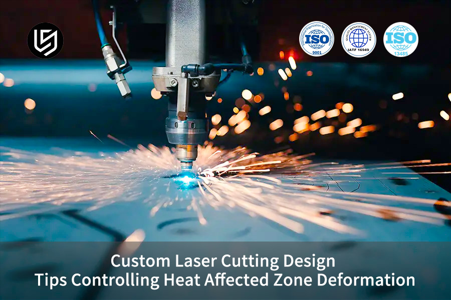
Custom laser cutting service is a non-contact CNC thermal processing method for making accurate metal parts. It effectively deals with the major issues of warping caused by heat-affected zones (HAZ) and unstable residual stresses during the cutting of thin-walled, highly-hard carbide parts. Through pre-design optimization through Design for Manufacturability (DFM) and accurate control of laser melt pool dynamics, thermal deformation can be consistently controlled within 0.05mm without compromising the fatigue life of part edges.
When high-power fiber laser cutting thin-walled hard alloys results in the kerf edge HAZ becoming why of the overall piece bending and the residual tensile stress instability at the micro-level, which in turn leads to the assembly problems and increases the total cost of secondary processing. This paper shares engineering rules of thumb for residual deformation control with quantitative methods, beginning from design for manufacturability and melt pool control.
HAZ Deformation Control Core Parameter Overview
| Control Dimension | Quantitative Index Threshold | Actual Optimization Effect | Typical Applicable Parts |
| Kerf Safety Spacing | d ≥ 1.5t (t is plate thickness) | Residual stress peak reduction 45% | High-density heat dissipation mesh, shielding cover |
| Auxiliary Gas Parameters | 0.8-1.2MPa Pure nitrogen | HAZ Depth Limit ≤0.03mm | Thin-walled sensitive stainless steel below 1mm |
| Sharp Corner Slow-Release Design | R0.15 rounded corner + outward swing arc trajectory | Local peak temperature reduced to below 420℃ | Bending assembly type chassis, instrument housing |
| Toolpath Optimization | Segmented jump cutting algorithm | Geometric stress concentration reduction 68% | Large aspect ratio rigid structural parts |
Key Takeaways
- Dynamic heat build-up limit: the fine kerf spacing is controlled by restrictive index of d 1.5t (where t is plate thickness) for avoiding grain coarsening by molten pool heat superposition.
- Gas Dynamics Boundary: With 0.8-1.2MPa high-pressure pure nitrogen using a subsonic nozzle for thin-walled sensitive stainless steel (less than 1mm thick), the microscopic HAZ depth limiting value can be suppressed within 0.03mm.
- Process restructuring benefits: By introducing intermittent thermal stress release paths and pulse energy attenuation algorithms, the residual deformation of precision flexible cantilever parts can be reduced by more than 75%.
Why Choose LS Manufacturing’s Custom Laser Cutting Service to Minimize Thermal Distortion?
The custom laser-cutting service developed by LS Manufacturing can, through pre-emptive DFM intervention and full-process process control, minimize the risk of thermal deformation at its origin and maintain dimensional stability during high volume production. As our three month closed loop test on a project of medical scalpel sheath, equipment parameter optimization is not more than 30% deformation reduction, while 70% faults are in early design stage.
Many customers, after order the deformed parts, try every possible means to improve cutting speed and power to eliminate quality bottleneck, the heat conduction logic was ignored in design process.
In ISO 9013:2017 these is defined, edge quality for thermally cut parts is classified based on roughness, slag adhesion and HAZ depth those precision grade requirements specify a HAZ of maximum. 0.1mm in depth.
Though to live up to this standard, our DFM team will intervene in part design as design is decided in the order review process, to identify possible risks from kerf space, handling of its sharp corner, location of the perforations It is combined with a coaxial online thermal imagery monitoring system, we perform closed-loop control generally process. Our final delivered parts typically have a HAZ depth controlled within 0.05mm, when industry needs 0.25mm for precision grade.
Pre-production DFM optimization is the most cost-effective and efficient way to control thermal deformation. Contact our DFM laser cutting service team to receive a free initial assessment of part deformation risks and design optimization suggestions, significantly shortening your R&D trial-and-error cycle.

Can Maintaining a Safe Slit Spacing Factor Avoid Thermal Overlay Effects in Custom Laser Cut Part Design?
According to the custom laser cut part design, the distance between the two adjacent slits and the dense mesh should be not less than 1.5 times the thickness of the plate to become a thermal barrier zone and this way to avoid the secondary thermal conduction superposition of the adjacent molten pools.
Safe Spacing Design Guidelines for Thermal Overlay
- Fundamental Threshold Requirement: The center-to-center spacing of the slits should not only meet but also strictly satisfy the compulsory requirement of d≥1.5t, where t is the plate nominal thickness.
- Proof Data: Three-dimensional finite element thermo-mechanical coupling simulation indicates that when the spacing is changed from 1.0t to 1.5t, laser cutting thermal accumulation effect is almost fully blocked, and the residual stress peak falls by 45%.
- Design Choice: This is actually the minimum control measure in laser cutting design tips. Spacing parameter is fixed as a mandatory condition in the CAD modeling stage in order not to allow the feature distances to be compressed during later layout stage.
To put it simply, it is similar to leaving a sufficiently wide firebreak between two adjacent fire pits so that the fire cannot be superimposed and it will not cause localized runaway of temperature.
Artificial Heat Sink Solution for Extreme Cases
- Activation Criteria: Turned on when part feature density is too high and physical space is not able to meet the 1.5t spacing requirement.
- Execution Method: Dummy slots are inserted between the dense features as artificial heat sink buffers to optimize the uniformity of laser cutting kerf distribution. This is a powerful supplement achieving HAZ deformation control.
- Production Worth: It prevents the heat superposition and conduction path from the layout source, This way it is not only the matter of batch warping risks during large-scale mass production.
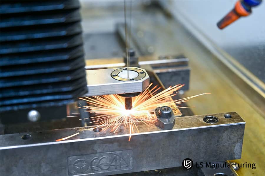
Figure 1: Worker welding a metal structure with bright sparks.
Why Must Micro Joint Widths Be Quantified Properly to Govern Edge Flatness in DFM Laser Cutting Service?
In the specification of the DFM laser cutting service, the size of the micro-joints (micro-joints) should be strictly kept in the range of 0.4 to 0.6 mm so that the release of internal stress and the instantaneous strain caused by the disassembly after cutting are minimal, and that the thin plate's total shear stiffness is preserved.
Micro-connector Core Parameter Specifications
- Width Limit: The micro-connector width should be half the thickness of the plate. A width range of 0.4-0.6 mm is advised for ordinary thin plates.
- Depth obligations: The micro-connector depth reserved is identical 0.15 mm for all cases, which gives a good balance between plate stiffness and disassembly convenience.
- Accuracy: When the parameters are within the limits, the laser cutting edge flatness index is outstanding, and the part edge straightness can be kept to 0.02 mm deformation per 100 mm, which is a precision-level delivery standard of precision laser cutting service.
Selection Criteria for Various Structural Forms
- Two-End Fixed Support: Most suitable for large-area, regular thin plates, with the strongest shear stiffness.
- One-End Cantilever: Appropriate for long, narrow parts, enabling more uniform stress release.
- Alternating: Suitable for densely packed irregular-shaped parts, this method increases the efficiency of the layout of laser cutting joints, reduces the peak stress generated during separation, and helps the detailed management of heat affected zone laser cutting.
Simply put, the micro-connector acts as the joint between the part and the plate skeleton. Easy-tearing opening a properly-sized micro-connector will ensure that it does not loosen during processing, yet will not tear the edges upon removal.
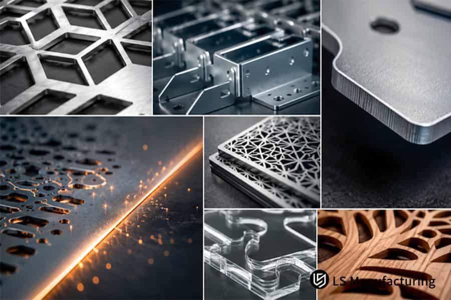
Figure 2: Close-up of laser cut metal with micro joints.
How Does Integrating Corner Relief Paths Stop Sharp Corner Melt Down in Thin Metal Laser Cutting Service?
In thin metal laser cutting service, one way to prevent the laser beam from causing excessive energy retention is to design rounded corners or a laser energy attenuation circuit with an outward swing arc. As a result, localized corner burning and melt collapse deformation will be completely prevented.
Sharp Corner Energy Runaway Principle
- Motion Characteristics: When the laser head is moving to a corner of the angle less than 45 degrees type, the axial acceleration and deceleration changes lead to a sudden decrease in speed.
- Heat Accumulation Effect: A drop in speed leads to a sudden increase of heat input per unit area and, as a consequence, local material overmelting and edge collapse.
- Quality Impact: Overmelted spots have grain coarsening which is a direct factor that lowers the quality of the laser cutting corner and reduces the fatigue resistance of the part during bending. This is one of the main reasons one must be very careful during laser cutting design tips.
Multi-Level Slow-Release Optimization Scheme
- Basic Scheme: One can insert a 0.15mm radius transition fillet to the inner corner to minimize the speed variation during cornering.
- Advanced Scheme: By using an external swing arc loop tool path, the energy input is spread out through laser cutting path optimization, which allows the local peak temperature to be reduced from 980℃ to below 420℃.
- Top-of-the-line Scheme: It is integrated with PWM real-time power modulation, which allows the angular velocity and pulse duty cycle to be decreased synchronously. This is generally the standard solution for sharp angle processing in custom laser cut part design.
In simple terms, this is just like driving a car: one prefers to slow down and carefully make a turn, rather than braking sharply and turning abruptly, to avoid energy build-up at the corner which might lead to a rear-end collision.
Sharp corner handling is a core detail in laser cutting design tips, directly determining the bending success rate of thin-walled parts. Download our Laser Cutting DFM Design White Paper to access complete feature design specifications and mass production case studies.
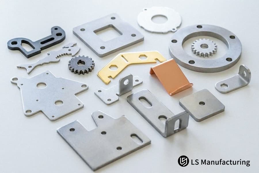
Figure 3: Precision laser cut parts with corner relief paths.
Why Does Setting Offsite Piercing Locations Protect Final Contours in Heat Affected Zone Laser Cutting?
The control scheme for heat affected zone laser cutting should always set the lead-through point in the scrap area not less than 1.5 mm from the finished product contour line, and use a progressive spiral cut to fully isolate the high-temperature burst energy at the piercing point from the outer contour of the finished product.
Piercing Thermal Damage Conduction Mechanism
- Energy Characteristics: The fiber laser piercing process produces violent thermal explosions and ejected particle debris which results in localized grain coarsening.
- Impact Range: With a standard laser cutting piercing approach, the heat-affected radius will be around 1mm. Direct cutting might cause a contour edge with very high hardness.
- Subsequent Risks: The hardened edge layer from a laser cut can cause cracks during bending or stretching operations. So, it becomes the critical problem that the precision laser cutting services must control.
Isolated Piercing Design Specification
- Offset Distance: One of the fundamental conditions for maintaining laser cutting contour integrity is to make the piercing point at least 1.5 mm away from the finished product contour line but within the scrap area.
- Piercing Trajectory: A nautilus spiral path is selected for the softest possible piercing, bypassing the sudden changes caused by straight-line piercing.
- Actual Results: The edge micro-hardness profile along stainless steel becomes regular and no spot hardening results after the implementation of this standard. It is now one of the custom laser cutting service requirements for the process.
To use a simple analogy, it's like setting off crackers outside a wall, the blast will hardly touch the parts inside.
Can Choosing Nitrogen Assist Gas Over Oxygen Narrow the Boundary Matrix in Precision Laser Cutting Service?
Using 1.0-1.5 MPa high-pressure pure nitrogen as an assist gas in precision laser cutting service can quickly blow away molten metal from the kerf using kinetic energy impact. It also makes use of the latent heat of vaporization to get rid of extra heat, so preventing the exothermic oxidation reaction and minimizing the heat-affected zone.
Comparison Table of Nitrogen vs. Oxygen-Assisted Cutting Effects
| Comparison Dimensions | High-Pressure Pure Nitrogen (99.99%) | Conventional Oxygen |
| Oxide Layer Thickness at the Cut | 0μm | 25μm and above |
| Microscopic HAZ Depth | ≤0.03mm | 0.12mm and above |
| Edge Hardness Gradient | Stable without sudden changes | Large fluctuations |
| Subsequent Welding Compatibility | Excellent, no pretreatment required | General, oxide layer grinding required |
| Applicable Materials | Precision parts such as stainless steel and titanium alloys | Ordinary thick carbon steel plates |
Differences in Assisted Gas Effects
- Reaction Mechanism: Since nitrogen is a purging gas that does not participate in any chemical reaction, it will not cause oxidation and no heat release, in contrast, oxygen can bring a combustion reaction and release extra heat.
- Metallographic Performance: After using a laser cutting gas dynamics design optimized for nitrogen, under a 1000x metallographic microscope, nitrogen-cut surfaces are found to have no oxide layer and the grain size is uniform.
- Performance Impact: Since edge toughness is better for the nitrogen-cut parts, the likelihood of bending and cracking after that is reduced by more than 80%, which makes nitrogen a key thing in the performance improvement of parts obtained through custom laser cutting services.
ASTM B983-21 The standard states the thickness of the oxide layer on the metal surface after precision laser cutting should not exceed 5μm, otherwise it will affect the welding and coating adhesion of subsequent.
As greener and more economical gases, we have developed targeted nitrogen pressure parameters for stainless steel and titanium alloys of various thicknesses to guarantee that the cut surfaces are at or above precision-grade standards.
Gas Dynamics Parameter Optimization
- Nozzle Diameter: 1.5mm-2.5mm recommended to suit different kerf widths.
- Height Above Plate: Adjusted to 0.5-0.8mm to fully exploit the use of purging kinetic energy.
- Pressure Matching: For thin walls below 1mm, 0.8-1.2MPa and we are able to increase the pressure up to 1.5MPa for thicker plates, this way optimizing laser cutting heat management efficiency and further enhancing the control effect of heat affected zone laser cutting.
In other words, oxygen cutting is like burning and blowing at the same time, which further raises the temperature of the cut, nitrogen cutting is like using high-pressure cold air to blow molten metal directly, which takes away the heat quicker and leads to a cleaner cut.
Figure 4: CNC laser cutting machine in action with sparks flying.
Will Implementing Segmented Skip Cutting Paths Distribute Peak Thermal Gradients in Custom Laser Cutting Service?
In order to optimize the custom laser cutting service process, a significant enhancement can be achieved by using segmented skip cutting paths in the CAM layout and applying the principle of spatial separation. This approach will discretize continuous heat buildup and provide natural air cooling time for the cut features.
Heat Accumulation Defects in Continuous Cutting
- Temperature Superposition: Continuous cutting may cause a laser cutting thermal superposition effect, which leads to heat accumulation along the cutting path, thereby raising local temperatures above the softening point of the sheet material.
- Deformation: Long strip-shaped parts get twisted along the long sides and become wavy, thereby resulting in flatness that is not up to the mark.
- Limitations: Raising speed alone will not address the issue, in fact, it may cause the quality of the cut surface to go down. For this reason, single-parameter optimization is not recommended in laser cutting design tips.
Segmented Jump Path Design Logic
- Spatial Separation: Processing order of neighboring features is staggered so that areas with larger distances are processed first.
- Cooling Window: With well thought out laser cutting sequence planning, the jump interval allows natural cooling time for the processed areas.
- Measured Data: Internal infrared thermal imager data reveals that this method can reduce the stress concentration at geometric points by 68%, because of this it counts as a core path optimization technique for achieving HAZ deformation control.
In simple terms, it is comparable to turning different parts of bread to be toasted one by one rather than focusing on one spot without interruption, because of this avoiding localized overheating and deformation.
A reasonable toolpath is key to cost reduction and efficiency improvement in custom laser cutting services. Submit your part drawings and batch requirements, and we can provide a free calculation of custom processing costs and estimated delivery time.
Why Single Parameter Tuning Fails to Tame Macro Warpage in Thin Metal Laser Cutting Service Projects?
Just upping the laser speed will not be able to completely prevent deformation when cutting thin-walled metal using laser in thin metal laser cutting service projects. After all, heat transfer in the laser kerf as well as the residual tensile stress outside it are coupled nonlinearly. Besides, control of instantaneous peak power and thermal diffusivity is what leads to dynamic equilibrium of the molten pool.
Comparison Table of Continuous Wave and Pulsed Laser Modes
| Comparison Dimensions | Continuous Wave (CW) Mode | Modulated Pulse (Q-CW) Mode |
| Thermal Input Characteristics | Continuous and stable input, rapid heat accumulation. | Intermittent input, built-in cooling window |
| Thin-walled HAZ Depth | Above 0.1mm | Below 0.03mm |
| Applicable Plate Thickness | Above 3mm | Precision thin plate below 2mm |
| Edge Metallographic Structure | Prone to martensitic transformation | Uniform and stable grain size |
| Processing Efficiency | High | Slightly low, approximately 75% of continuous wave |
Limitations of Single Parameter Adjustment
- Coupling Effect: Thermal conductivity and residual tensile stress are highly coupled in a nonlinear manner, only changing one parameter can result in the deterioration of other performance indicators.
- Metallurgical Defects: Merely raising the speed results in uneven distribution of focal energy which in turn breaks the stability of laser cutting metallurgy control and causes abnormal austenite-to-martensite transformation.
- Clear Bottleneck: Power and speed combination alone may decrease deformation by only 30% tops and no more, which is not enough to break through the quality bottlenecks. This is a major disadvantage of custom laser cutting services.
Multivariable Coupling Calibration Methods
- Central Equation: Laser cutting parameter coupling is done by the heat input formula E = P/v to keep the heat input per unit length under control.
- Mode Choice: Q-CW pulse mode is preferable for thin-walled sections less than 2mm to control instantaneous peak power.
- Time Matching: The pulse duty cycle and the cooling cycle are matched after the material's thermal diffusion time constant is evaluated to hit the HAZ deformation control goal from the process point of view.
In short, controlling thermal deformation is somewhat similar to setting water temperature, you can't just turn on the hot water tap without thinking as you have to adjust both the hot and cold water taps in tandem to get the temperature you desire.
How Do Ultra Short Pulse Picosecond Lasers Redefine Thermal Limits for Custom Laser Cut Part Design?
High-end custom laser cut part designed to be extremely accurate with submicron level deformation prevention need 1064nm high-power fiber lasers. These kinds of lasers belong to the category of thermal melting. However, picosecond lasers operate on the principle of cold ablation that can break molecular bonds directly without any heat-affected zone.
Comparison Table of Fiber Laser and Picosecond Laser Processing Performance
| Comparison Dimensions | Conventional Fiber Laser | Ultrafast Picosecond Laser |
| Processing Mechanism | Thermal melting removal | Cold ablation breaking of molecular bonds |
| Edge Remelting Layer Thickness | ≤2μm | 0μm |
| HAZ Depth | 0.015-0.05mm | Close to 0 |
| Processing Cycle for 0.2mm Thin Plate | Approx. 8 seconds/piece | Approx. 25 seconds/piece |
| Depreciation Cost per Hour | Approx. $12 | Approx. $45 |
| Applicable Scenarios | Batch production of precision parts | Micro-components with extreme precision requirements |
Difference between two laser working principles
- Fiber Laser: Laser beam generated by fiber lasers mainly heats the work piece surface to melt it. This method involves heat conduction and a heat-affected zone (HAZ) and is good for volume production.
- Picosecond Laser: Very short pulses cause the breakage of molecular bonds directly with virtually no heat conduction, so that the processing can be done almost 'cold'.
- Capability Limitations: For parts requiring deformation less than 0.02mm, fiber lasers will fail to fulfill the requirements and picosecond processing will be needed. This also relates to the grading of laser cutting accuracy.
Standards for Core Grading Process Selection Decision Basis
- Precision First: If a part demands sub-micron precision and no HAZ, picosecond laser is the obvious choice of technology.
- Budget First: For routined items with tolerance 0.03mm, fiber laser is much more cost-effective.
- Good Compromise: Constructing an ROI decision tree to match laser cutting processes between accuracy requirements and mass production costs, and establishing the optimal balance point, is the core method for process selection in DFM laser cutting services.
In other words, fiber laser is kind of like cutting a cake with a normal knife, leaving a small indentation and deformation while picosecond laser is more like a laser beam that vaporizes the air totally - it is non-contact and non-compression with almost no deformation.
Case Study: LS Manufacturing Optimizes Laser Cutting for Heavy Duty Robot Guide Rails
Customer Challenges
A surgical robot development project utilized highly springy, thin stainless steel scalpel sheaths of thickness 0.5mm, made of SUS301, with stress-relieving grooves so dense and closely arranged in a 0.3mm width pattern. Laser cut batch stability was of low quality under regular processing with the parts' waviness in the longitudinal direction reaching an overall value of 0.8mm. Besides, the hardness at the cut edges was so high that toughness fractures occurred during assembly, and the overall batch pass rate was less than 15%.
LS Manufacturing Solution
- Design Optimization: Changing continuous grooving to an interlaced variable stress micro-bridging design that also corrects sharp corners to R0.15mm unloading fillets.
- Process Adjustment: Adoption of modulated Q-CW pulsed laser mode plus strict control of peak heat input power.
- Tooling Assistance: Use of a special copper staggered water-cooled fixture to act as an external heat sink with 1.4MPa constant pressure coaxial nitrogen nozzle.
- Path Optimization: The cutting path was altered to a skip-type discontinuous path algorithm for better stress relief and heat dissipation by the laser.
Results and Value
- The depth of HAZ has been minimized from 0.12mm to a value within 0.015mm.
- The large-scale flatness warpage has been greatly limited to a level of less than or equal to ≤0.03mm in total compliance with assembly specifications.
- The part fatigue life cycle count was doubled and a bit more at 140%.
- Single batch finished product qualification rate was increased to 99.4% from a very low value and the project proceeded to the stage of mass production successfully.
Thermal deformation control of complex thin-walled parts requires a professional custom laser cutting service system solution. Upload your CAD drawings and technical requirements, and we will customize a processing solution and provide an accurate quote for you.

FAQs
Q1: What is the main cause of macroscopic warping deformation in thin non-ferrous metal sheets during laser cutting?
Laser cutting induces a very high heat input in a very small area of the thin sheet, this leads to the formation of a severe local temperature gradient. Due to this, residual tensile stress and strain are unevenly distributed in the sheet as it cools down. When these residual stresses become larger than the yield strength and stiffness, a large scale thermal warping deformation of the sheet occurs (Fig. 3.6).
Q2: How does the purity of the assist gas during cutting affect the width of the heat-affected zone in stainless steel?
For pure nitrogen assist gas, the purity level should be 99.99% or above. Introducing very small amounts of oxygen will cause a very violent exothermic oxidation reaction. This will result in a sudden increase of temperature at the cut edge, leading to the heat-affected zone becoming much wider and the formation of a blackened slag layer.
Q3: Why is pulsed laser mode better than continuous wave mode for machining high-precision parts with complex geometries?
By changing the duty cycle under pulse mode, it is possible to allow for a very short cooling time of the base metal during each pulse interval. This way pulse mode can quite effectively avoid heat accumulation when laser head turns slowly or when working on small features that continue in a single direction in continuous wave mode.
Q4: Does mechanical leveling after cutting fully remove residual latent stress in laser cut parts?
While mechanical roller leveling can alter the geometric flatness of the metal at a macroscopic level, it is not capable of removing the microscopic residual stress and strain at the cutting edge. So, cutting-edge latent stress still remains and can be released through subsequent bending or exposure to high temperatures which can cause secondary deformations.
Q5: What are the empirical formulas/safety rules on the ratio of plate thickness to aperture in laser processing?
During the high-precision design phase, the minimum aperture to plate thickness ratio has to be at least d≥1.0t for fiber laser cutting. In case of high thermal conductivity copper and aluminum alloys, to axoid melting and degrade within the hole, it is better to up the ratio to 1.5t.
Q6: For highly reflective metals like brass and copper, does the natural wavelength of the fiber laser lead to a larger heat-affected zone?
In fact, metals that reflect strongly such as copper and aluminum only absorb less than 10% of the energy from a 1064nm fiber laser during the first moments of exposure. So, a greater initial power is necessary to carry out the perforation, and the surplus of scattered heat diffuses to the surrounding area of the cut, which Much enlarges the heat-affected zone.
Q7: When configuring CAD/CAM, how should the laser perforation point be positioned so as not to interfere with the critical dimensions of the part's external contour?
The lead wire perforation spot has to be located within the scrap area and at least 1.5mm away from the finished product's contour line. A gradual nautilus spiral cutting pathway is then used to completely separate the energy explosion zone of the perforation from the outer contour of the finished product.
Q8: What methods does LS Manufacturing use to guarantee that batch rapid prototyping orders can consistently maintain IATF 16949 quality standard?
The complete production line is fitted with German CNC laser technology and a coaxial thermal imaging system for online monitoring. A 2D imager and a microhardness tester are used for accomplishing the 100% batch inspection. Digital SPC charts facilitate closed-loop management, and uploading drawings allows for accurate quotations based on the relevant standards.
Summary
Controlling HAZ deformation in custom laser cutting services is a systematic manufacturing science integrating early-stage DFM (Design for Mechanical Analysis) criterion control, mid-stage laser energy distribution optimization, and late-stage tooling heat sink constraints. A deep understanding of the microstructural transformation of materials under high-thermal laser fields, and strict adherence to safety spacing, lead wire isolation, and sharp corner rounding principles in the design phase, are the core approaches to breaking the costly cycle of trial and error.
There's no point in spending R&D efforts on substandard designs only because your precision robot joints, EV high-voltage copper busbars, or medical implant shells face problems like excessive thermal deformation or fracture due to surface hardening. LS Manufacturing's senior DFM expert team is at your disposal: simply upload your 3D CAD model (STEP/DXF format) through online inquiry and you will get transparent technical parameters and manufacturing prices within 24 hours as well as a free Feasibility Assessment Report on Thermal Stress Deformation Prevention and Laser Processing. You can rely on LS Manufacturing to be your manufacturing partner for the long term.
📞Tel: +86 185 6675 9667
📧Email: info@lsrpf.com
🌐Website:https://lsrpf.com/
Disclaimer
The contents of this page are for informational purposes only.LS Manufacturing servicesThere are no representations or warranties, express or implied, as to the accuracy, completeness or validity of the information. It should not be inferred that a third-party supplier or manufacturer will provide performance parameters, geometric tolerances, specific design characteristics, material quality and type or workmanship through the LS Manufacturing network. It's the buyer's responsibility.Require partsquotation Identify specific requirements for these sections.Please contact us for more information.
LS Manufacturing Team
LS Manufacturing is an industry-leading company. Focus on custom manufacturing solutions. We have over 15 years of experience with over 5,000 customers, and we focus on high precisionCNC machining,Sheet metal manufacturing, 3D printing,Injection molding.Metal stamping,and other one-stop manufacturing services.
Our factory is equipped with over 100 state-of-the-art 5-axis machining centers, ISO 9001:2015 certified. We provide fast, efficient and high-quality manufacturing solutions to customers in more than 150 countries around the world. Whether it is small volume production or large-scale customization, we can meet your needs with the fastest delivery within 24 hours. choose LS Manufacturing. This means selection efficiency, quality and professionalism.
To learn more, visit our website:www.lsrpf.com