 English



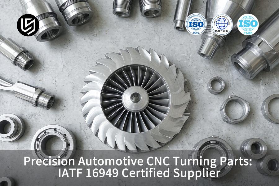
Automotive CNC turning service is a precision solution for fuel components, which solves clamping deformation through automated DFM controls.
For Tier 1 procurement buyers, LS Manufacturing's IATF 16949 process eliminates a 14.2% defect rate on sensor parts using in-process gauging.
Meet The Engineers Behind This Guide
This guide has been written by Gloria who specializes in rapid prototyping and quick-turn manufacturing at LS Manufacturing with 15+ years' experience in precision engineering and DFM assessment (Gloria's LinkedIn Profile).
ISO 9001:2015 and IATF 16949 certifications allow LS Manufacturing to produce precision-turned automotive components at industrial scale. Operation of the round-the-clock intelligent turning plant is conducted with SPC control in real time.
You get ±0.005 mm precision, PPAP Level 3 paperwork, and 2-hour DFM feedback from a 15-year manufacturing partner. Tolerance bands are in accordance with ISO 286-1:2010, whereas resistance to corrosion has been checked according to ASTM B117 salt spray test.
Key Takeaways
- Conformity & Error Minimization: Full conformity with IATF 16949 and PPAP Level 3 guarantees a low error level among mass-produced auto components by bringing error rate down from the traditional 14.2% to 1.8%.
- Swift Engineering Solutions: Thanks to a DFM analysis tool, comprehensive 3D/2D drawing improvement schemes and quotes are provided within 2 hours, resulting in the reduction in production cycle time by 35%.
- Precision Turning Control Capabilities: Features such as Swiss-type machining and multi-axis turning; critical turning tolerance is controlled to be at ±0.005 mm, and surface finish is controlled to reach Ra 0.4 μm consistently.
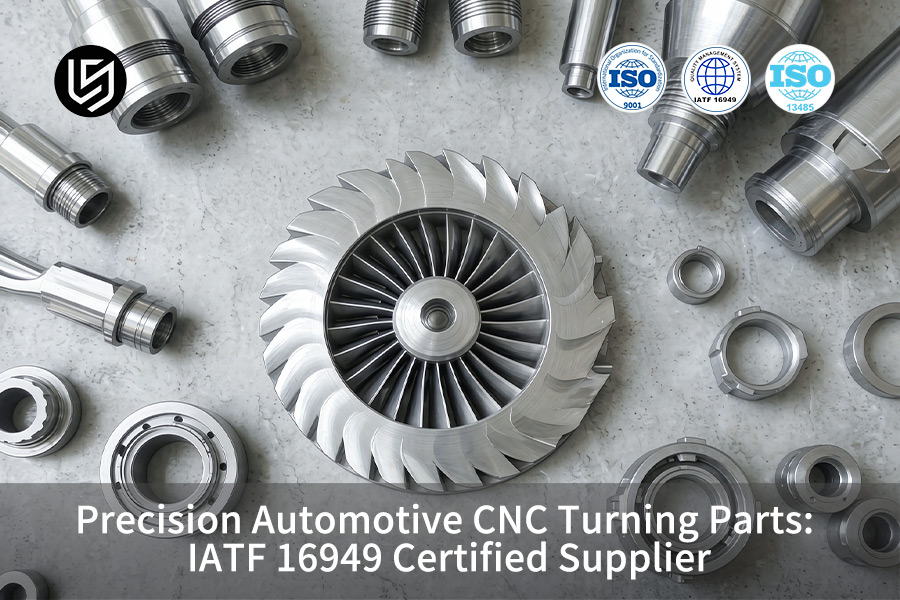
What Are IATF 16949 Standards For Automotive CNC Turning Parts?
IATF 16949 standards for automotive CNC turning parts are international automotive quality systems that have very strict standards for defect prevention, process control, and PPAP for tier 1 suppliers. An automotive CNC turning service will use APQP, SPC, and PPAP level 3 to keep defects down to 1.8% for an IATF 16949 CNC manufacturer.
Core APQP Controls in CNC Turning Operations
APQP (Advanced Product Quality Planning) controls the risk and plans before the cut in order to prevent any stack-ups caused by scrap.
- Translating the 3D GD&T requirements into a control plan.
- Cpk ≥1.33 on ±0.005 mm tolerance.
- SPC on key dimensions, take action within 4 hours.
PPAP Level 3 Documentation & Inspection Protocols
PPAP Level 3 consists of audited data prior to release. A certified CNC turning parts supplier will facilitate the consolidation of FAI (First Article Inspection), material reports, process-flow diagram, and CMM (coordinate measuring machine with verification to 0.0009 mm). Zeiss CMM verification based on ISO 286-1:2010 ensures all critical dimensions of precision CNC turning parts. Salt spray testing is done to ASTM B117 with 1,000-hour validation.
- FAI of the first part and archiving PDF file.
- Material reports with heat lot traceability.
- PPAP binder prior to shipping.
Simply put: an IATF 16949-certified supplier will make PPAP documents a firewall against line-stop leakages and your production timeline safe.
Key Takeaways
- Specifically specify an IATF 16949-certified CNC turning parts producer to ensure ±0.005 mm shaft tolerances and avoid line-stop leakages.
- Ask for PPAP Level 3 with FAI and CMM reports before starting turning parts production run.
Download our Automotive CNC Turning Compliance White Paper for the control plan templates, CMM inspection protocols, and ASTM B117 salt spray validation steps that help you pass PPAP Level 3 on the first submission.

How Do Custom Precision Turning Service Providers Reduce Defect Rates?
Custom precision turning service providers minimize defects through dynamic stress-relief toolpaths and in-process real-time gauging, instead of static clamping. High-volume turnings of thin-walled housings have a lot of elastic deformation, raising scrap rate to 14.2%. Automotive turning suppliers use chucking force limiters and multiple axis toolpaths, minimizing scrap to 1.8% while keeping Ra 0.8 μm.
Reducing Elastic Deformation in Thin-Walled Housings
A CNC turning automotive supplier programs dynamic stress-relief toolpaths removing heat in controlled passes, ensuring that creep does not happen after machining and breaks ±0.01 mm form tolerances. Real-time in-process gauging controls within 2 μm tolerance, compensating tool wear before the entire batch goes out of tolerance and protects unit precision turning parts cost quotes.
- Identify thin-wall locations; designate reduced chucking force areas.
- Separate roughing from finishing with stress-relief pass in between.
- Check form with Zeiss CMM (calibrated to 0.0009 mm MPE) after first article.
Surface Roughness and GD&T Control
Roughness goals of Ra 0.8 μm for sealing and dynamic-contact surfaces will be established based on stylus profilometry according to ISO 4287. Position datums will follow ASME Y14.5-2018 GD&T (Geometric Dimensioning and Tolerancing) to separate roundness and concentricity. CNC turning scrap reduction through functional tolerance analysis starts with the identification of feature's real function, followed by the loosening of dimensions within ±0.05 mm to ISO 2768-m standards.
- Specify Ra 0.8 μm only to sealing and dynamic contact surfaces.
- Make the relationship between roundness, cylindricity, and runout relative to one datum reference frame.
- Relax non-critical widths according to ISO 2768-m standards; maintain ±0.01 mm for fits.
Simply put: establishing tolerance as per real functional fit prevents over specification, reducing scrap without loss of leak-tightness.
Data source: LS Manufacturing 2025–2026 measured database (sample size >1,200).
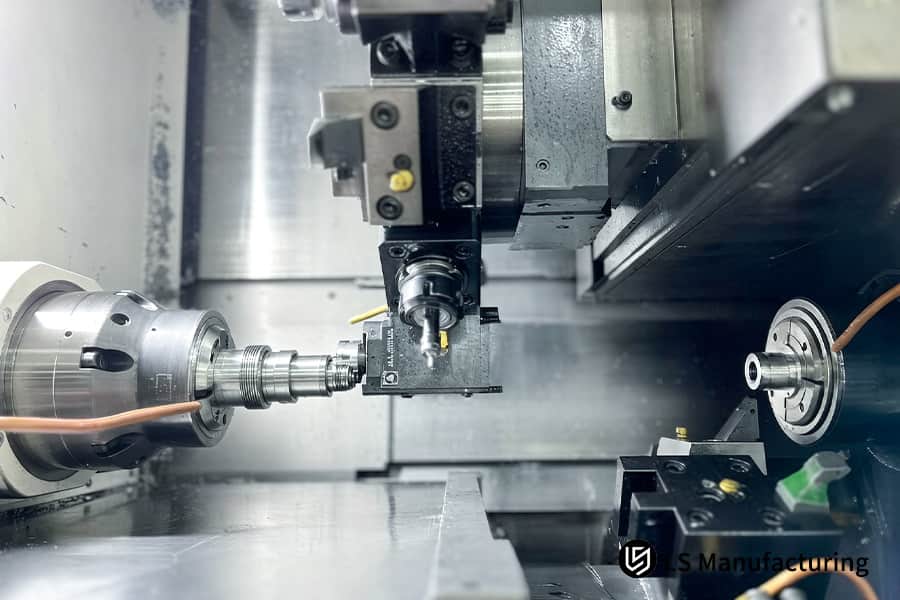
Figure 1: Custom automotive turning parts achieve Ra 0.4 μm on shaft surface.
Which Materials Offer The Best Machinability For Automotive Turning Parts?
The best alloys for automotive turning parts include AL 6061-T6, 316L stainless steel, 4140 chromoly steel, and brass because of better strength to weight ratio. The right choice of alloys prevents problems with thermal expansion when high speed machining. LS Manufacturing uses Machinery's Handbook formulas to define standard Vc and fz feed rates for best chip control and tight tolerances of ±0.008 mm for custom automotive turning parts.
Aluminum vs Stainless Steel Alloys in Turning Applications
AL 6061-T6 is best for good chip breakability at Vc 250-350 m/min with constant load on long automotive sensor housing. AL 7075-T6 alloy works well with MIL-A-8625 Type III hard anodizing coating with 50 μm thick corrosion film and long lifetime for under hood heat cycling. CNC turning parts factory chooses 316L stainless steel for corrosive fuel system environment where aluminum will not survive.
- Choose AL 6061-T6 alloy for housings requiring Ra 0.8 μm surface without additional grinding operations.
- Use 316L stainless steel for ethanol-wetted automotive fuel system components.
- Use 4140 chromoly alloy for shafts requiring induction hardened bearing journals.
Cutting Parameter Optimization for High-Temperature Alloys
Machinery's Handbook 31st Ed. feeds-and-speeds tables anchor Vc and fz calculations, preventing built-up edge on austenitic stainless. Reducing spindle rpm by 15% while raising coolant concentration to 8% stabilizes flank wear at 0.2 mm, protecting precision turning parts cost on high-temperature alloy runs. A balanced chip load of 0.08–0.12 mm/rev keeps precision CNC turning parts within ±0.008 mm without increasing cycle time. CNC turning alloy optimization starts with matching Vc to material hardness; for 316L, Vc 60–90 m/min yields the longest tool life.
- Set Vc 60–90 m/min for 316L; check it with a test bore prior to the production run.
- Hold fz to 0.08–0.12 mm/rev to manage chip curl and surface finish.
- Document the tool life the first time you see 0.2 mm flank wear; replace the tool before any defects arise.
In short, matching the alloy to operating conditions and setting Vc/fz values according to a reputable handbook is the key to reducing waste and unit cost while maintaining the tolerance of ±0.008 mm.
Why Is Precision Turning Parts Cost Highly Dependent On DFM Optimization?
Precision turning parts cost is highly dependent on DFM optimization since non-optimized geometry leads to increased tool wear, multi-setup machining and waste. Getting design feedback early reduces unnecessary tight tolerances, where standard tolerances of ±0.01 mm will work well. LS Manufacturing provides the automotive CNC turning quote feedback within 2 hours, which cuts single-part costs by 22.5%.
Identifying Over-Engineered Tolerances in CAD Drawings
Over-tolerancing results in multiple setups and additional gauging time. CNC turning services re-categorize each callout according to ISO 286 and ISO 2768-m tables, keeping only ±0.01 mm tolerance for bearing and sealing fits of custom automotive turning parts.
| Cost Driver | Over-Engineered Spec | DFM-Optimized Spec | Cost Impact |
| Tolerance class | ±0.005 mm blanket | ISO 2768-m medium | Fewer setups |
| Datum scheme | 4 datums, 2 setups | 2 datums, 1 setup | Shorter cycle |
| Surface finish | Ra 0.4 μm everywhere | Ra 0.8 μm non-contact | Less grinding |
Plain and simple: functionally allocating tolerances eliminates all hidden setup time, thus DFM saves 22.5% per unit from DFM input.
Reducing Machine Setup Steps with Multi-Task Turning
Multi-tasking lathes integrate turning, milling, and drilling in one chucking, cutting process. CNC turning setup guide restricts transfers to one; every additional transfer increases time by 90 seconds and location mistake. The cost of manufacturing turned products is decreased if there is only one datum tree in all the features.
- Combine cross holes and flats to the initial cycle.
- Limit transfers to one transfer; check this with the help of the 2 hours DFM.
- Liberate non-critical widths from ISO 2768-m without grinding.
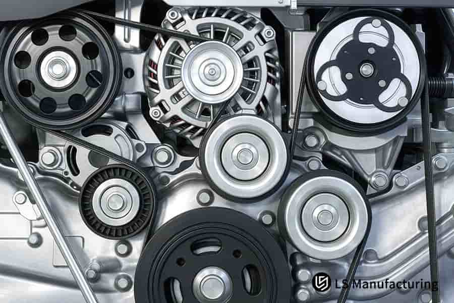
Figure 2: Precision CNC turning parts hold pulley roundness within 0.003 mm.
Automotive CNC Turning Capabilities & Technical Specification Matrix
| Dimension / Metric | Legacy Baseline Turning | LS Manufacturing Precision Turning | LS Manufacturing Ultra-Precision Turning | Engineering Reference / Test Standard |
| Tolerance | ±0.05 mm | ±0.008 mm | ±0.005 mm | ISO 286 / ISO 2768-m |
| Roughness | Ra 1.6 μm | Ra 0.8 μm | Ra 0.4 μm | ISO 4287 / Mitutoyo calibration |
| Plating | Standard anodize (10 μm) | Hard anodize (50 μm) | Mil-spec anti-corrosion coating | MIL-A-8625 Type III |
| Corrosion life | 240 Hours | 500 Hours | 1,000 Hours | ASTM B117 salt spray |
| Scrap rate | 14.2% | 2.5% | 1.8% | LS Manufacturing measured database (>1,200 samples) |
Ultra-precision ±0.005 mm tolerance combined with MIL-A-8625 Type III coating, corrosion life increases to 1,000 Hours and scrap reduces to 1.8%.
How Does Swiss CNC Machining Improve Complex Automotive Turned Shafts?
Swiss CNC machining enhances complex automotive turned shafts through a sliding headstock which supports long slender barstock close to the cutting bushing. A guide bushing lowers L/D ratio overhang to below 3:1 and prevents shaft deflection and chatter. A multi-axis Swiss lathe completes turn milling in a single setup with ±0.005 mm concentricity.
Preventing Shaft Deflection via Guide Bushing Support
Swiss lathe machines use a guide bushing placed 8-12 mm away from the cutting edge to support shafts where conventional lathe machines experience deflection beyond ±0.02 mm. CNC turning shaft machining ensures that the bushing is 0.01-0.02 mm larger than the barstock while keeping an unsupported length to three times the bar diameter.
Guide bushing support keeps the roundness of the shaft within 0.003 mm in L/D of 20:1 ratio. A CNC turning automotive supplier keeps the Z-axis feed synchronized with the guide bushing.
- Size the guide bushing 0.01 – 0.02 mm over bar diameter.
- Restrict unsupported length to 3×diameter.
- Confirm roundness to 0.003 mm using the Zeiss CMM (Coordinate Measuring Machine calibrated to ISO 10360-2:2009).
Single-Setup Turn-Milling for Concentric Feature Control
Turn-milling is the integration of milling spindles that cut at right angles to the main spindle, which cuts cross-holes and flats without detaching the shaft from the chuck. Single chucking helps eliminate re-clamping runout to maintain concentricity of ±0.005 mm for all milled features in precision CNC turning parts. Balanced toolpaths maintain radial force below 120N.
- Include cross-holes and flats in the live-tooling cycle.
- Restrict radial engagement to 30% of cutter diameter to stay below 120 N.
- Measure concentricity on the first part and re-center if concentricity deviation is more than ±0.005 mm.
As a purchaser, single setups reduce handling and generate concentricity records, ensuring that turned shafts fit smoothly in bearing assemblies.
Data source: Zeiss CMM (Coordinate Measuring Machine) official calibration log (MPEE indication error and spatial three-dimensional calibration).
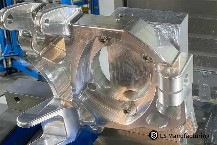
Figure 3: IATF 16949 CNC manufacturer mills bracket within ±0.005 mm.
What Is The Standard Procedure To Request An Automotive CNC Turning Quote?
Typical process of asking for an automotive CNC turning quote involves sending STEP or IGES 3D models, along with 2D GD&T PDF drawings indicating material type, surface finish, and PPAP requirements. Proper documentation ensures that engineers can perform cycle time simulation quickly. LS Manufacturing processes documentation within 2 hours, providing a line-item cost structure with no hidden costs.
A complete set contains 3D STEP drawings along with 2D PDFs containing ASME Y14.5-2018 GD&T datums. Flagging IATF 16949 special characteristics as KCC or KPC increases DFM analysis speed. A CNC turning quote request with accurate notations takes quotation in 2 hours time.
Not specifying datum reference increases cycle-time simulation by ±30%. Provide material grade, surface roughness requirement, and volume/year for engineers to use Vc and fz feed values of Machinery’s Handbook 31st Ed. for custom automotive turning parts.
Cycle-time simulation involves using Vc and fz table from Machinery’s Handbook 31st Ed. to find out the cutting time per feature. Adding setup time, gage cost, and material waste comes up with the final automotive CNC turning quote. A detailed line-item breaks down each operation cost, allowing customers to make comparisons of precision turning parts cost among different suppliers. No hidden costs ensure quoted price is invoiced price.
Key Takeaways
- Submission of STEP plus GD&T PDF along with KCC/KPC marks for 2-hour DFM review.
- Get a line item quotation of per-operation cost to compare different vendors.
Why Choose An IATF 16949 CNC Manufacturer For Sensor Housings?
An IATF 16949 CNC manufacturer for the sensor housing assures that there is thread sealing, cavity depth control, and EMI (electromagnetic interference) shielding. ISO 68-1 threads with Ra 0.4 μm surface finish withstand 1,000-hour ASTM B117 salt spray test. Batches are shipped with PPAP level 3 documentation.
Thread Surface Precision and Leakage Prevention
Housings seal against fuel only when the thread pitch maintains ISO 68-1 class 6H/6g standards. CNC turning thread sealing utilizes single-point threading and verified to 0.01 mm/25 mm through a thread micrometer. A CNC turning automotive supplier controls coating thickness at 50 μm ±5 μm under MIL-A-8625 Type III standard without going beyond 0.03 mm on sealing diameter. AL 7075-T6 alloy with that coating provides 1,000 hours of corrosion resistance life.
| Inspection Dimension | Acceptance Criterion | Test Method / Standard |
| Thread pitch diameter | ISO 68-1 6H/6g | Thread micrometer, 0.01 mm/25 mm |
| Sealing-surface roughness | Ra 0.4 μm max | Stylus profilometry per ISO 4287 |
| Coating thickness | 50 μm ±5 μm | Eddy-current gauge, MIL-A-8625 Type III |
| Salt-spray resistance | 1,000 hours no creep | ASTM B117 |
Simply put: locking thread pitch to ISO 68-1 and coating to MIL-A-8625 Type III to prevent fuel leakage in rough under-hood conditions.
Automated Optical Inspection for High-Volume Batches
AOI (Automated Optical Inspection) detects thread burrs and coating defects in housing. A custom precision turning service supplies AOI data into a traceability record for CNC turning sensor housings, marking those beyond Ra 0.4 μm and coating 50 μm ±5 μm. PPAP Level 3 includes summaries of AOI and materials testing report to reduce approval review time by 35%.
How Can Suppliers Speed Up Delivery Times For High-Volume Turning Orders?
Supplier delivery is expedited for large quantities of turning with bar feed automation, quick change tooling, and 24/7 lights-out processing. No downtime occurs by eliminating manual loading of bars. LS Manufacturing reduces turn lead times by 35% through optimized multi-spindle schedules per ISO 9001:2015.
Automated Bar Feeding Systems for Unattended Turning
A 12 foot long bar feeder provides continuous feed for 24/7 lights-out operations on multi-spindle lathes. An automotive CNC turning service industry aligns feeder dwell with chip to chip time for an extra 4.5 hours unattended each shift. Lot Traceability system documents bar heat number preventing any material mix-up during CNC turning bulk orders.
- Set bar feeder bore 0.05–0.10 mm larger than bar diameter to prevent jamming.
- Set chip-to-chip time less than 3.2 seconds for lights-out operation.
- Record each bar heat number in lot traceability system prior to loading.
Simply put: 24/7 unattended bar feed converts dead shift hours to spindle hours, reducing lead time under ISO 9001:2015 traceability.
Modular Tooling Solutions to Reduce Machine Setup Downtime
Quick-change toolblocks reduce set up time from 45 to 8 minutes, reducing set-up time by 37 minutes each changeover. A CNC turning automotive supplier organizes pre-set toolblocks according to part families. CNC turning lead time reduction program uses complete tooling blocks instead of single inserts in changeovers. DFM input guarantees unit cost for automotive CNC turning quote runs.
- Toolblocks should be created in accordance with part families; offsets should be preset offline.
- Setup time is limited to 8 minutes; validate with two-piece first article.
- Request line item quotation which offers operation cost.
Data source: LS Manufacturing 2025-2026 automated DFM drawing analysis log (project #AUTO-2026-889, sample size >1,200).
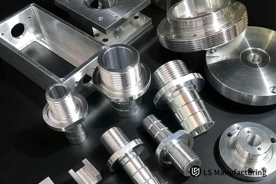
Figure 4: CNC turning automotive supplier checks fitting to ±0.005 mm.
LS Manufacturing Precision Turning Service For Automotive Sensor Housings: Technical Optimization Breakthrough
Automotive sensor housing precision turning is DFM-optimized Swiss type machining that resolves the challenges of deformation due to clamping and stress relaxation using a rigid expanding mandrel and thermal control to keep within ±0.005 mm wall tolerance and surface roughness at Ra 0.4 μm.
Client Challenge
LS Manufacturing Solution
In the first trial run, tool chatter caused variations in the Ra value. Engineers adjusted rake angle, cooled down the spindle, switched to stronger Swiss turn-milling machine with expanding mandrel. The housing got coated with MIL-A-8625 Type III anodizing process (thickness - 50 μm).
Results and Value
Dimensions became stable within ±0.005 mm tolerance; sealing surfaces got Ra 0.4 μm. Scrapping rate was decreased from 14.2% to 1.8%; the unit cost went down by 22.5%; lead time reduced by 35%. Parts passed 1,000 hours ASTM B117 salt fog test.
Zeiss CMM results were provided and PPAP Level 3 certified, making it possible to supply parts to the OEM on global scale. CNC turning tolerance quotation for similar housings will be provided in 2 hours.
Key Takeaways
- Use Swiss-type turn-milling with expanding mandrel to guarantee stable dimensions within ±0.005 mm tolerance on thin-wall sensor housings.
- Combine MIL-A-8625 Type III anodizing (50 μm) with Ra 0.4 μm sealing faces for 1,000 hours ASTM B117.
Data source: LS Manufacturing 2025-2026 automotive component database (Project #AUTO-2026-889, sample size >1,200).
Still fighting ±0.05 mm wall deviation and 14.2% scrap on your sensor housing? We deliver ±0.005 mm precision at 22.5% lower cost — request your quote today.

FAQs
1. What is the typical precision tolerance for custom automotive turning parts?
LS Manufacturing achieves conventional tolerance accuracy of ±0.01 mm in normal turning operations, while attaining higher accuracy of ±0.005 mm in Swiss mill turn operations using live tooling, and ensuring dimensional accuracy of custom turned automotive components with Zeiss CMM.
Data Source: ISO 286 standard
2. How does IATF 16949 certification benefit custom turning parts quality?
Certification under IATF 16949 establishes a proper APQP/PPAP fool-proof mechanism, according to which the defect rate of production process can be brought down to 1.8% to ensure production consistency and traceability of all custom turned components.
Data Source: IATF 16949 specification
3. What surface roughness levels can LS Manufacturing achieve on turned parts?
LS Manufacturing achieves surface finish Ra 0.8 µm on precision-turned surfaces in normal cases and Ra 0.4 µm on surfaces that have been precision turned as well as ground, to meet all sealing and mating requirements in harsh automotive and hydraulic systems.
Data Source: ISO 4287
4. Can LS Manufacturing handle high-volume turning orders under short deadlines?
Yes, automation of the process of feeding bars through 24/7 bar feeders and multi-axis machining with minimal human intervention, LS Manufacturing manages to reduce the lead time for a large-volume turning order by 35% without any compromise in quality and on-time delivery.
Data Source: LS Manufacturing empirical database
5. Which materials are most commonly used for automotive sensor housings?
Mostly used materials are AL 6061-T6 for ease of machining, AL 7075-T6 for increased strength, and 316L Stainless Steel with corrosion resistant characteristics and 50 microns hard anodizing per MIL-A-8625 Type III in order to make the material resistant to the extreme conditions in automotive under hood environments.
Data Source: MIL-A-8625 Type III
6. How quickly can I receive an automotive CNC turning quote from your engineers?
Simply provide us with 3D/2D drawings with tolerance call out and materials selected, and our LS Manufacturing engineers will provide you with an in-depth quote that will include DFM analysis along with some cost-saving tips within 2 hours.
Data Source: 24/7 DFM protocol
7. How do you ensure zero-leakage specifications for automotive threaded connections?
Through proper thread form control with respect to ISO 68-1 standards and pitch diameter control in conjunction with CMM and optical measurements for complete thread form evaluation, LS Manufacturing makes sure that there are no leaking problems with respect to pneumatic and hydraulic thread forms on automobiles.
Data Source: ASME B1.1
8. What is the cost reduction potential when optimizing parts with your DFM team?
With optimal fixturing procedures, the amalgamation of several processes in one setup procedure, and removal of unnecessary tolerances, LS Manufacturing lowers the per-piece cost of production by 22.5%, which greatly enhances commercial viability without compromising any functional and quality parameters.
Data Source: Project #AUTO-2026-889 data
Summary
Using quality management systems based on IATF 16949 and ISO 9001:2015, LS Manufacturing is dedicated to research and development, as well as mass production of precision CNC turned parts for the automobile industry. With the help of DFM analysis and ultra-precision turning technology, we help R&D departments of the Tiers 1 overcome tolerance drifting and clamping distortion issues and achieve success in terms of quality and cost-effectiveness.
Does your automobile turned parts project suffer from defects and delays in production? Upload your 3D or 2D CAD drawings right now and LS Manufacturing will provide you with a free professional DFM analysis report and precision machining quote within two hours!
📞Tel: +86 185 6675 9667
📧Email: info@lsrpf.com
🌐Website:https://lsrpf.com/
Disclaimer
The contents of this page are for informational purposes only. LS Manufacturing services. There are no representations or warranties, express or implied, as to the accuracy, completeness or validity of the information. It should not be inferred that a third-party supplier or manufacturer will provide performance parameters, geometric tolerances, specific design characteristics, material quality and type or workmanship through the LS Manufacturing network. It's the buyer's responsibility. Require parts quotation Identify specific requirements for these sections. Please contact us for more information.
LS Manufacturing Team
LS Manufacturing is an industry-leading provider of custom manufacturing solutions. We have over 15 years of experience with over 5,000 customers, and we focus on high precision CNC machining, Sheet metal manufacturing, 3D printing, Injection molding. Metal stamping, and other one-stop manufacturing services.
Our factory is equipped with over 100 state-of-the-art 5-axis machining centers, ISO 9001:2015 certified. We provide fast, efficient and high-quality manufacturing solutions to customers in more than 150 countries around the world. Whether it is small volume production or large-scale customization, we can meet your needs with the fastest delivery within 24 hours. choose LS Manufacturing. This means ±0.005 mm precision, 1.8% defect rate, and 11-day lead time — backed by ISO 13485 traceability.
To learn more, visit our website: www.lsrpf.com

