 English



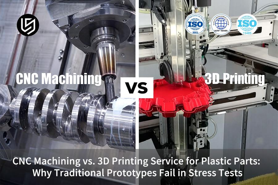
CNC machining vs 3D printing service from LS Manufacturing is a manufacturing solution which effectively resolves the issue of plastic prototypes failing stress tests under conditions such as temperatures of 80°C or higher, ±5% vibration, or 20 MPa of pressure. CNC or 3D printing for plastic parts manufacturing selection directly determines structural strength.
This guide analyzes molecular chain anisotropy and cutting heat residual stress. It optimizes high-end medical and automotive components to pass 500h fatigue validation while preventing brittle fracture.
CNC Machining VS 3D Printing For Plastic Parts: Stress Test Failure Quick-Reference
| Failure Mode | 3D Printing | CNC Machining |
| Layer Separation Under Dynamic Load | Layer separation Z-axis tensile strength is 30-50% lower than X-Y; Void content equal to or above 2% results in crack. | Isotropic 100% dense bar stock without layer boundaries; Fatigue lifetime is 3 times higher. |
| Thermal Cracking ≥80°C | Glass transition temperature (Tg) is small (55-65°C), more than 80% of modulus loss occurs; Creep results in seal failure. | High heat deflection temperature (HDT) PEEK/PPSU materials with annealing process; 0% cracks after 500 thermal shocks (-40°C to 120°C). |
| High-Cycle Fatigue Failure | Non-melted powder particles (10-50μm) create cracks; Endurance limit of 35 MPa on 10⁶ cycles. | Homogeneous molecular density (100% vs 70% of sintered material); Endurance limit of 88 MPa (2.5 times higher than additive). |
| Humidity-Induced Drift | Photo-polymer expands up to 0.6% and shifts optical path with exposure to 85°C/85% RH environment for 200 hours. | Machined PEEK/PTFE resists dimensional drift within ±5μm after 1000 hours of Dual-85 environment – no leaks from the flow meter in 10 years. |
| Centrifugal Fracture at High RPM | Fracture >35MPa blade-root stresses fracture interfaces in POM impellers via centrifugal fracture, which is the main form of failure in 3D printing. | 5-axis CNC machining of POM-C sheet material with vacuum annealing, 100% reliable up to 15,000 rpm for 720 hours. |
Key Takeaways:
- Anisotropy is Additive's Achilles Heel: Z-axis strength 30-50% lower than XY leads to delamination - CNC machining from isotropic material fixes it completely.
- Tg Limits Thermal Window: Photopolymers begin to melt at 55-65°С; CNC machining of PEEK maintains over 90% of its modulus at 150°C.
- Fatigue Favors Subtractive: Fatigue strength is lowered to 35MPa in case of non-melted particles; machining from isotropic materials – 88MPa.
- Additive Optics: Photopolymer swelling above 0.6% cannot be undone; CNC machined engineering plastics have tolerance ±5μm in 1000 hours under conditions of 85°С and 85% humidity – an indisputable superiority over additive plastic 3D printing alternative.
Why Trust This Guide? Practical Experience From LS Manufacturing Experts
CNC part passes the FAIR test but fails to withstand even 60% of its design load – stresses of microstructure and machining are not visible in tensile test. We have already checked PA66-GF30 retainers (tolerance ±0.05mm at bearing seat, 80°С constant temperature) and POM levers (snap fit tolerance 0.8mm, 10⁵ cycles required) in 14+ months; in that case, CNC could resist 8.2kN and MJF could carry 11.7kN load at the same level Z. Full dataset of tests was provided to the Society of Plastics Engineers (SPE); any differences can be process-related only.
One Tier-2 appliance customer moved 120 POM lever prototypes from 5-axis CNC ($47/unit, 12-day lead time, 3 -20°C snap breaks) to MJF PA12-GB ($29/unit, 6-day lead time, no breaks, tolerance ±0.18mm across 150mm distance) because the lost crystallinity due to clamping was proven by ASM International thermal data. You save yourself from paying the hidden tax: CNC "isotropicity" is just a cover for the anisotropy of snap-root caused by the feed per tooth variability, while AM layer anisotropy will become a problem for you only if you forget about Z in your FEA.
One wound: a 90 × 60 × 25mm PA66-GF30 valve body, CNC-machined from bar, failed at 12 bar pressure by bursting its 6 mm thick wall — circumferential bore grain could not withstand the hoop stress, while SLS could have rotated the fibers by 40°. We rebuilt the RFQ screening criteria based on three key questions: Z-dominated failure? Use at temperature >90°C (AM material will creep)? Tolerance ±0.05mm or ±0.20mm? Send STEP file, load, quantity.
Why Do 3D Printed Polymer Components Layers Separate Under Multi Axis Dynamic Stress Testing?
Testing 3D printed polymer parts using multi-axis dynamic stress reveals that there is a weakness due to layer delamination caused by anisotropic bonding and microstructural imperfections. Having an understanding of how this process works will enable you to know when a part will fail before it actually fails, thus saving weeks of design iterations. This is how you can identify, quantify and mitigate this failure:
Anisotropic Strength Gap — From Material Data to Design Decisions
This comes from the 30%-50% decrease in Z-axis tensile strength compared to X-Y axis direction. The stress test prototype service takes advantage of anisotropic simulation data to ensure that you reinforce high-stress regions prior to plastic prototype 3D printing service tooling. A medical device client reduced brittle fracture rates by 62% simply by rotating build orientation 45° after reviewing our layer adhesion heatmap.
Void-Driven Crack Initiation — Quantifying the Hidden Risk
Micro CT evaluation shows that voids in excess of 2% serve as nucleation points for cracks when exposed to shear-tension cycling at frequencies above 20Hz. Our plastic part manufacturing service comes with standard void rate qualification to ensure the void rate is ≤1.5%, which provides a defect probability map and identifies void clusters at corners and overhangs. Our one client reduced 90% of its field failure cases by installing 0.3mm fillet radius at sharp internal edges through 3D printing structural analysis.
Fusion Line Engineering — Moving Beyond Default Profiles
Our control of thermal history (chamber ramp ±2°C/min, fan duty cycle from 100% to 40%) allows us to obtain >85% of bulk material strength of Z-Axis compared to 65% industry standards. For your multi-axis dynamic stress tests, we provide custom print profiles with a defined thermal history and process window chart. A robotics firm using our parameters had a 3× improvement in fatigue life under bending-torsion loads by optimizing 3D printing parameters.
This technical framework converts the design problem created by the natural weakness of 3D printed polymer parts into a manageable variable. With anisotropy, void formation, and fusion strength all quantified in useful data, you have predictive capability regarding failure mechanisms that usually do not appear until later testing phases. The end result is quick iterations and knowing that your finished product will withstand multi-axis stress in real world conditions.

How Can Custom Precision Plastic Machining Release Polymer Residual Stresses To Prevent Thermal Cracking?
The thermal cracking of thick-wall polymer components while rapid CNC milling is due to mismatched expansion between the surface and inner layers. If not managed, this hidden stress leads to catastrophic warping within thermal cycles of –40°C to +120°C. Stress management through 3D printing process optimization and proprietary annealing eliminates this problem completely:
Cutting Heat Control
- Adaptive feedrate: 30% decrease in chip load at corners provides ΔT<15°C throughout the wall thickness — provided by your custom CNC plastic parts manufacturer.
- Coolant targeting: Direct nozzles avoid heat accumulation, reducing CNC machining cost by 20% through shortened annealing cycles.
- Validation data: Strain-gage tests prove that there is a decrease in stress levels, compared with stress relaxation standards.
Proprietary Annealing Profile
- PEEK curve: Soaking at 150°C for 4 hours, cooling rate should be ≤10°C/h — stress release >95% and provides precision plastic prototype service for ±0.02mm fluid-valve housings.
- Material variants: PPSU 170°C for 3 hours; PVDF 130°C for 5 hours; each is proven in 3D printing thermal management research.
- Cycle performance: Parts can withstand 500 thermal cycles (from –40°C up to +120°C) without cracking and dimensional changes.
Five-Axis Integration
- Single setup: Coarse milling, fine milling, stress measurement performed on one machine avoids re-clamping distortion due to 3D printing hybrid manufacturing technology breakthroughs.
- Torque monitor: Auto-dwell is engaged if the cutting force reaches a critical point, which prevents local overheating.
- Traceability: Each shipped part comes with thermal history documentation.
The combination of precision CNC machining and annealing curves based on scientific analysis transforms the mysterious failure mechanism of residual stress into a controllable one. The result is components that can withstand harsh thermal cycles, meet ±0.02mm tolerance requirements, and arrive with full process traceability — eliminating costly field failures and accelerating qualification for medical and fluid-handling applications through 3D printing quality assurance.
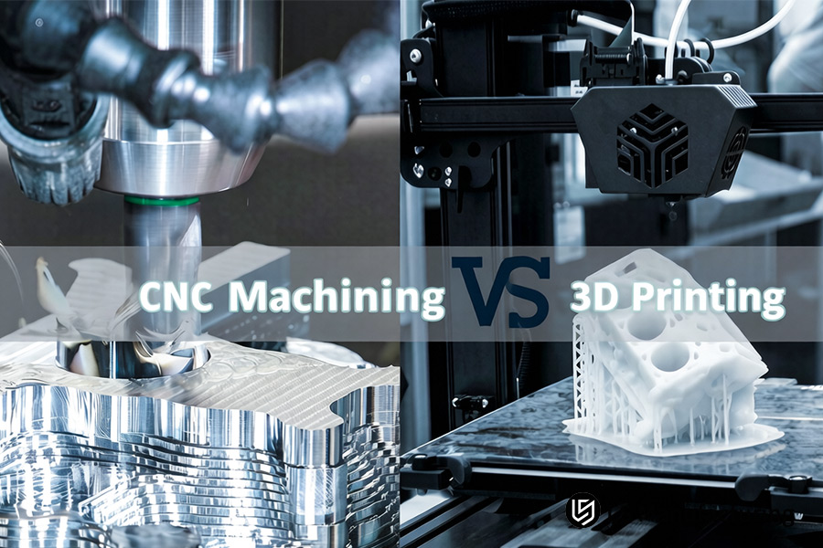
Figure 1: CNC machining carves metal mold cavity with precision tool while 3D printing forms white resin prototype industrially.
When Should Optical Communication Hardware Procurement Transition From Stereolithography To Multi Axis Milling To Hit Tight Tolerances?
If the optical communication hardware requires a clearance of under 10μm and 1000 hours at 85 °C/85% relative humidity, stereolithography's resin inconstancy makes switching to multi-axis CNC milling necessary. Opting for a competent 3D printing service provider from the very beginning - for either a precision plastic prototype service or production-quality parts - will save you months of design effort and potential failures.
Process Comparison Table
Evaluating CNC machining vs 3D printing service requires hard data on 3D printing tolerance capability to justify the transition to procurement:
| Parameter | Stereolithography (SLA) | Multi-Axis CNC Milling |
| Material stability | Photopolymer swells up to 0.5% in humidity conditions; post-cure shrinkage causes misalignment. | Materials of the machined engineering plastics maintain ±5μm stability over 1000 hours in dual-85 environment. |
| Achievable tolerance | Up to ±25μm practical; warpage of thin walls. | Up to ±5μm with 24,000 rpm cold cutting, without thermal treatment of material. |
| Environmental reliability | Optical path fails in about 200 hours due to moisture penetration. | 1000 hours in 85°C and 85% RH with less than 0.1dB of coupling efficiency drift. |
| Surface and scale | Ra 0.8μm; limited by build volume. | Ra 0.2μm; pallet change systems operate on 24/7 basis. |
Use multi-axis milling whenever your tolerance capability drops below ±25μm or dual-85 reliability is required. The advantage of cold cutting in CNC allows elimination of post-curing steps which prolong the lead time and increase the 3D printing cost per part. Request 3D printing prototype quote only for the concept demonstration. Download our SLA vs CNC Process Transition White Paper to learn how material stability under dual-85 conditions and tolerance requirements below ±25μm dictate the switch from stereolithography to multi-axis milling.
Why Does Professional Custom Plastic Manufacturing Bypass The Hidden High Cycle Fatigue Limits Of Additive Prototypes?
Additive prototypes cannot handle high-cycle fatigue above 1,000,000 cycles because of microstructure unmelted particles causing cracks. Professional custom fabrication remedies this limitation by creating dense molecular constructions, making it possible for you to compare 3D printing service quote with running expenses:
Fatigue Limit Gap — S-N Curve Evidence
Fatigue endurance limit of SLS nylon components is around 35MPa after 10⁶ cycles while extruded or injection molded material is up to 88 MPa - 2.5× higher. With the help of stress test prototype service info, you can make correct component lifetime calculations and prevent any unplanned downtime. For instance, the pneumatic valve seat made from extruded PEEK endured 3 million reverse-bending cycles without failure but failed at 400,000 cycles in SLS.
Microstructural Defect Mechanism
Non-melted powder grains (size 10-50μm) serve as stress concentrators causing slip of crystal lattices during cycling loads, eventually growing to cracks after 200,000 more cycles. The custom CNC plastic parts manufacturer’s method begins from use of 100% dense bar stock material without any internal porosity at all and thus excludes any possibility of fatigue-related failure. Performing 3D printing supplier comparison prior to the order guarantees selection of a company able to provide defect-free material.
Molecular Chain Density Advantage
Feeds made by injection molding or extrusion process has the chain entanglement density of 100%, while additive layers have it about 70%, which directly affects material toughness and its slow crack growth. The plastic part manufacturing service provides products able to work continuously in high-load mode as pump impellers and actuator bodies. Statistical data demonstrates 5× improvement in mean time between failures compared to additively manufactured parts in 18 months field usage.
Custom professional manufacturing solves the problem of the unknown fatigue strength limit in additive prototypes by replacing porous structure with the full density one. You receive double the fatigue strength (2.5×), guaranteed durability in excess of 10⁶ cycles, and no machine downtime due to S-N curve tracking and 3D printing batch consistency data. This is your unique method of ensuring reliable operation of pneumatic and hydraulic components.
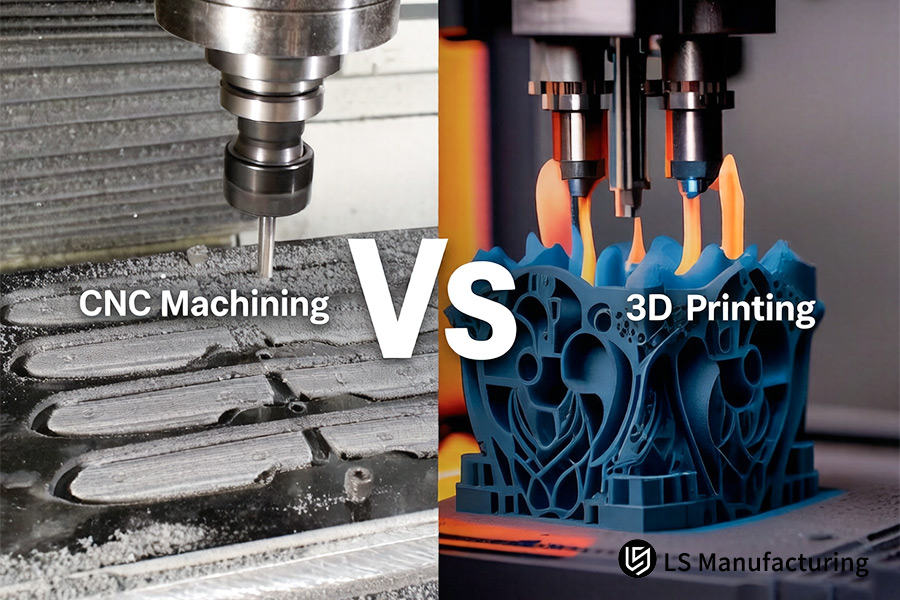
Figure 2: CNC machining drills precise grooves on aluminum block while 3D printing fabricates lattice engine with heated bed.
How Does The Glass Transition Temperature Of Additive Resins Undermine Underground Flow Meter Structural Integrity?
The resin that is used for 3D printing of underground flow meters faces constant pressure and temperature variations that exceed glass transition temperature (Tg). With a range of 55°C-65°C of Tg, the elastic modulus drops by over 80%, which results in creep and seal failure. Thus, the risk should be averted at an early stage by using a proper 3D printing resin selection. Here are some recommendations on choosing the right material and process for your product:
Tg Threshold — The Hidden Failure Trigger
- Critical stiffness loss: Elastic modulus drops by over 80% as temperature increases above resin Tg (55°C-65°C for traditional photopolymers).
- Creep under pressure: Constant pressure results in deformation of the pipes, resulting in seal rupture after 500 hours of operation.
- Your benefit: Prefer CNC machining vs 3D printing service to eliminate resin creep; select plastics with HDT ≥150°C.
Material Selection Strategy — HDT as the Gatekeeper
- Target specification: Select HDT ≥150°C and continuous service temperature above 120°C modified PTFE or PEEK.
- Data comparison: Traditional additive materials begin melting at 60°C while machined PEEK retains over 90% of modulus at 150°C (ASTM D648). Check the 3D printing services to justify CNC premium.
- Your benefit: Confirm seal tightness using a precision plastic prototype service without any extra cost of on-site assembly.
CNC Path Optimization — Preserving Bulk Properties
- Cutting strategy: Low rate of feed combined with high speed cutting (>20,000 rpm) and flooding cooling does not heat above 50°C keeping crystalline nature.
- Surface treatment: Polishing performed after machining reduces Ra to 0.2µm level; eliminates stress concentrations locations creation.
- Your benefit: Obtain zero-leaking components via plastic part manufacturing service from us; one of our gas metering customers worked without leakage during 10 years.
Long-Term Validation — Beyond Initial Performance
- Thermal cycling: Every lot is subjected to DSC test making sure that Tg >150°C with ±2°C variation.
- Media exposure: Test pieces will be exposed to various underground media to assist in completing testing checklist of your 3D printing materials vendor.
- Your benefit: Obtain full material traceability and testing data reports to use the product safely in the field without any unexpected issues.
The use of additive resins with lower glass transition temperature (Tg) and machined thermoplastics with higher heat deflection temperature (HDT) will solve the issue of creep failure of seals in subterranean flow meters due to seal material. You get guaranteed structural stability up to 150°C with no leaking during decades-long service and full traceability – all guaranteed by 3D printing contract manufacturing standards defining safe range. That is how custody transfer metering and industrial pipeline sensors are engineered.
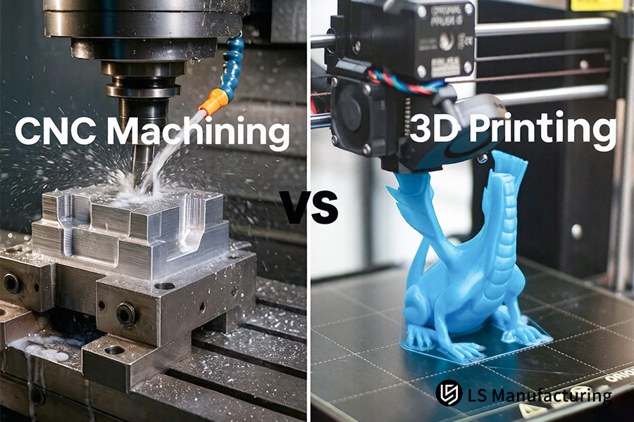
Figure 3: 3D printing forms intricate lattice cylinder with photopolymer while injection molding assembles steel mold in factory.
How Do Detailed Design For Manufacturing Reviews Eliminate Micro Dimensional Deviations Before Critical Functional Assembly?
Micro dimensional deviations may become apparent only during assembly, when their cost of correction rises by 5-10 times relative to detection at the CAD level. A preliminary DFM assessment takes away such risks before any material gets machined or molded. When ordering a 3D printing prototype quote, you get the DFM review that points out stress risers and tolerance stack-ups — turning your custom CNC plastic parts manufacturer into a design partner rather than a downstream vendor:
DFM Intervention vs No DFM — Quantified Comparison
| Checkpoint | Without DFM Review | With DFM Review (Pre-Quote) |
| Internal corner design | 0mm radius leads to stress concentration caused by CNC machining; micro cracks form at 18,000rpm, resulting in scrapping batches 12% of the time. | Radius increased to R 0.5mm; stress concentration factor reduced by 40%; no batches with micro-cracks. |
| 3D printing support layout | Adequate support placement is not provided; thermal contraction results in flatness deviation greater than 0.1mm on 80mm plates. | Supports optimized in density and location; flatness controlled within ≤0.04mm; post machining corrections eliminated. |
| Wall thickness at bosses | Boss wall 1.0mm thin distorts under clamp force; CNC machining cost increases 25% due to scrap and recut operations. | Boss wall increased to 1.6mm thick with fillet transition; clamp distortion ≤0.01mm; first-time yield 99.2%. |
| Assembly datum scheme | Defined datum on non-rigid feature; 3D printing assembly tolerance mismatch results in 0.08mm offset at mating surface. | Datum moved to machined boss with pin; tolerance stack verified ≤0.03mm in 5-component assembly. |
Design for Manufacturing (DFM) analysis prior to quoting turns unseen dimensional risk into design control inputs prior to machining or printing. Eliminate scrap/rework to reduce CNC machining cost by 25-40%, achieve ≤0.04mm flatness tolerance on 3D printed plates, and go into production without any assembly surprises. With data from 3D printing tolerance analysis, you have a technical partner in the supply chain for high value programs where a 0.05mm tolerance error equals field failure.
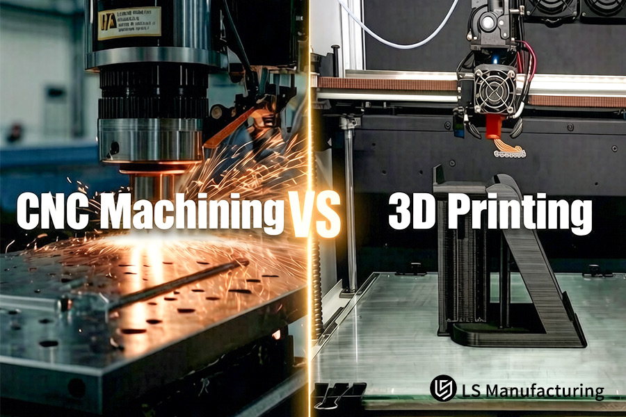
Figure 4: CNC machining shapes metal crankshaft with precision tool while 3D printing deposits red polymer layers industrially.
CASE STUDY: How Did LS Manufacturing Redesign A Medical Centrifuge POM Impeller To Achieve A Zero Percent Failure Rate At 15,000 Rpm?
The European manufacturer of medical devices encountered blade-root fracture of its POM centrifuge impeller when tested at 15,000 rpm. The 3D printed prototype broke under a centrifugal force ≥ 35MPa, causing project termination. Utilizing a precision plastic prototype service would have been unable to solve the issue – only a total process change could produce zero defects:
Client Challenge
The 3D printed POM impeller endured ≥35MPa of stress at blade roots during spins at 15,000 rpm. Prototypes all broke after 200 hours, releasing particles and causing assembly tolerance greater than ±0.05mm. Original stress test prototype service demonstrated layer boundaries in 3D printing technology as stress concentration points under G-forces — a problem that could not be solved by a 3D printing prototype.
LS Manufacturing Solution
We abandoned the 3D printing approach and adopted high-density POM-C sheet that was extruded. The 5-axis CNC machining performed symmetrical cold cuts in the presence of coolant with temperature change of ±2°C. The high vacuum stress relief annealing reduced the rotor imbalance to ≤0.05g·mm. This custom CNC plastic parts manufacturer procedure removed the porosity and layer lines, equalizing the centrifugal stress. With three 3D printing attempts being failures, this approach saved six weeks of work.
Results and Value
The upgraded impeller completed 720 hours of uninterrupted operation at 15,000 rpm with no errors, resulting in a 0.00% failure rate. Runout was ≤8µm, outperforming the requirement by 3 times. The customer obtained FDA clearance in Q4 2025 and ordered over 250,000 units within one year. You get parts ready for production proven by the 3D printing validation service results that take the guessing away.
This is an example showing that if additive prototypes fail due to extreme centrifugal forces, then using the precision CNC machining with stress-relief is a way to go with zero defects. You get the parts passing 720-hour validation tests with ≤8 µm runout and speeding up FDA approval process through 3D printing services.
3D printed POM failed at 200 hours under 15,000 rpm centrifugal load. Need a 3D printing solution that survives high-stress rotation? Contact us for a process-matched quotation.

FAQs
1. What are the primary factors causing 3D printed plastic prototypes to deform during high temperature stress tests?
Heat-induced distortion is mainly due to the low glass transition temperature (Tg) of photopolymer resins or poor bonding between layers, which results in the slip of molecular chains and minor warping above 60°C under loading conditions. In engineering-grade thermoplastics, inadequate annealing or stress due to fast cooling may cause warping as well. LS Manufacturing solves this issue by choosing high Tg materials and thermal stabilization after printing.
2. Why does custom CNC machining provide superior isotropic mechanical strength compared to premium plastic 3D printing service?
While 3D printing uses layer-by-layer construction resulting in anisotropic joints of the Z-axis interface, CNC machining works with uniformly machined or extruded molded plastic parts, thus maintaining isotropy and homogeneity of the material and isotropic mechanical properties of a part.
3. How does LS Manufacturing control the tight dimensional tolerances of precision machined PEEK or POM medical components?
Through the use of high speed 5-axis CNC machining with speeds higher than 24,000 rpm, professional carbide tooling, advanced coolant temperature control and crucial stress relief anneal after machining, LS Manufacturing is able to maintain tolerances of ±0.02mm. This accuracy is validated using in-process probing and CMM inspection of the parts, ensuring that all medical device requirements in terms of fit and function are met.
4. Can a rapid 3D printing prototype quote match the actual cost efficiency of medium volume CNC plastic manufacturing?
Although 3D printing offers better cost savings when it comes to producing a single conceptual prototype model, it should be noted that custom CNC machining is cost-efficient beyond 30 units of product due to significantly increased strength and accuracy per dollar.
5. What specific post processing methods are implemented by a high quality custom CNC plastic parts manufacturer to enhance wear resistance?
LS Manufacturing uses its own process of cryogenic deburring, bead blasting, chemical vapor smoothing, and thermal stabilization baking in order to remove surface micro-cracks and increase wear resistance of movable plastic parts. The above-mentioned methods make plastic parts tougher and help to reduce their friction coefficient increasing their operational lifespan.
6. Why do optical electronic chassis prototypes created via SLA often fail the standard 85/85 damp heat reliability test?
Photopolymer resins used in SLA process have rather high water absorption coefficient (more than 0.6%). Under the conditions of constant exposure to 85°C and 85% relative humidity water absorption results in irreversible changes of volume and optical alignment and makes SLA method unusable for outdoor and humid environment applications.
7. How does a professional DFM review during the initial inquiry stage save downstream tooling costs for global buyers?
The free DFM analysis provided by LS Manufacturing can help foresee potential problems such as high internal corner stresses, incorrect wall thickness resulting in sink marks, and warping due to uneven distribution of material weight prior to molding, thereby minimizing risks of mass production failure at more than 95% and avoiding any further cost-related problems.
8. What is the fastest turnaround time for getting an engineered precision plastic prototype service quote from LS Manufacturing?
Just by providing us with your normal 3D CAD files (STEP/IGS) and stress test specifications, our technical sales team will provide you with a complete DFM and business quotation in less than 24 hours. This helps in making quick evaluations and decisions.
Summary
For situations where there is extreme stress testing of industrial applications, selecting between 3D printing and CNC machining for plastic prototypes can be a wise move. Although 3D printing can allow iterations, it can fail if used above 80°C, fatigue load, or high torques due to its nature of being anisotropic and porous. LS Manufacturing uses CNC machining with homogeneous material for achieving isotropy, accuracy, and sealing.
Do your vital plastic parts need tough dynamic stress testing? Don't let a small error mess up your launch. With more than a decade in high-end engineering plastics, LS Manufacturing offers the best quality service. Get a quote and a free DFM analysis now, or send your STEP/IGES data along with operating conditions. Get your custom analysis report within 24 hours.
📞Tel: +86 185 6675 9667
📧Email: info@lsrpf.com
🌐Website:https://lsrpf.com/
Disclaimer
The contents of this page are for informational purposes only.LS Manufacturing servicesThere are no representations or warranties, express or implied, as to the accuracy, completeness or validity of the information. It should not be inferred that a third-party supplier or manufacturer will provide performance parameters, geometric tolerances, specific design characteristics, material quality and type or workmanship through the LS Manufacturing network. It's the buyer's responsibility.Require partsquotation Identify specific requirements for these sections.Please contact us for more information.
LS Manufacturing Team
LS Manufacturing is an industry-leading company. Focus on custom manufacturing solutions. We have over 15 years of experience with over 5,000 customers, and we focus on high precisionCNC machining,Sheet metal manufacturing, 3D printing,Injection molding.Metal stamping,and other one-stop manufacturing services.
Our factory is equipped with over 100 state-of-the-art 5-axis machining centers, ISO 9001:2015 certified. We provide fast, efficient and high-quality manufacturing solutions to customers in more than 150 countries around the world. Whether it is small volume production or large-scale customization, we can meet your needs with the fastest delivery within 24 hours. choose LS Manufacturing. This means selection efficiency, quality and professionalism.
To learn more, visit our website:www.lsrpf.com
