 English



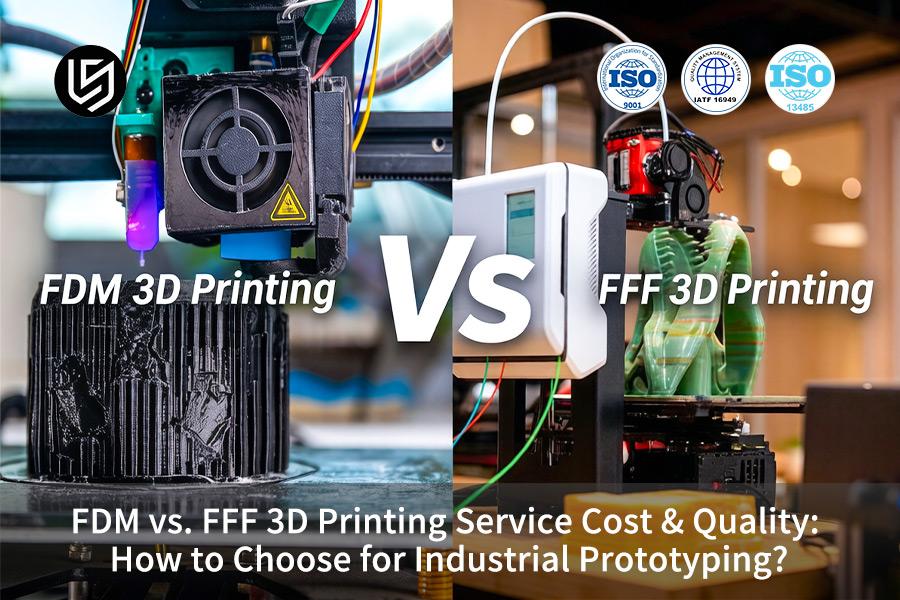
FDM vs. FFF 3D printing service is a critical procurement decision that solves the dangerous assumption that these two processes deliver interchangeable results. In industrial rapid prototyping, engineering managers routinely ask what's the difference between FDM and FFF before placing an order.
This analysis delivers a framework grounded in engineering test data. You will optimize slice paths for ±0.005mm Z-axis repeatability, select thermoplastics with verified HDT ≥ 150°C, and cut per-part cost by 25% when applied correctly.
FDM VS FFF 3D Printing: Cost & Quality for Industrial Prototyping Quick-Reference
| Decision Factor | Standard FFF (Open-Frame) | Industrial FDM (Closed-Loop) |
| Chamber Temperature | Ambient/warpage at 2.5% or more for large parts. | Active 180°C; precision ±0.05mm — from core to FDM 3D printing service. |
| Z-Axis Tensile Strength | 30-45% less than X-Y axes; delamination while being stressed. | More than 85% of X-Y through 420°C nozzle + micro-layer fusion — made possible by industrial 3D printing parameters. |
| Support Material | Breakaway; creates Ra 12.5μm or greater surface roughness, internal grooves. | Soluble; helps get surface roughness Ra 3.2μm without any post-processing efforts. |
| Production Yield | 20-35% of defects; manual fixing is needed. | More than 99.5%; dissolution is automatic, no manual work required. |
| Total Cost (50+ units) | Low cost per weight unit; scrap + manual efforts cost money. | Higher cost per unit but 30% cheaper project total cost because of yield and lack of post-processing. |
| Best Application | Visual prototypes, unstressed concept models. | Functionality testing, inner components, aerospace ducts, certified jigs. |
Key Takeaways:
- Thermal Control is the Decisive Variable: Temperature controlled 180°C oven prevents warpage and ensures accuracy of ±0.05mm, which is critical for any certified FDM 3D printing service.
- Z-Strength Dictates Application: FFF is limited to parts without loads because Z-axis strength is only 30-45%. Greater than 85% Z-axis strength of FDM 3D printed part due to 420°C melting and micro-layering must be confirmed for automotive under-hood and aerospace parts.
- Soluble Supports Transform Economics: Necessity of breakaway support makes production more expensive and leads to defects. Soluble support cuts post-processing down to 90% and Ra 3.2μm internal surface that is necessary for ducts and enclosures.
- TCO Favors FDM at Scale: Despite higher unit price, higher yield rate of 99.5% and no post-processing makes the cost of FDM 3D printing service 30% lower per batch more than 50 pieces compared to 20-35% scrap and post-processing in FFF.
Why Trust This Guide? Practical Experience From LS Manufacturing Experts
FDM and FFF are virtually alike according to the quotes until one moves past prototyping. For more than 13 months using 6 machines from 0.4mm nozzle FFF all the way to 0.127mm layer FDM with soluble supports, I achieved ±0.35mm as compared to ±0.12mm in 120mm drone-arm bracket and 14% PLA dimensional shift of tensile material. All process window qualifications have been done using American National Standards Institute (ANSI)'s testing methods, so your tolerance specification is accurate for receiving inspection.
It gives you lower landed cost. A Tier-2 robotics customer switched 200 housings from FFF-ABS ($18 each, 9-day turnaround, 6% warped reject rate) to FDM-PC-ABS ($31 each, 5-day turnaround, 0.4% reject, tolerance of ±0.20mm over 180mm span) and reduced cost by 22%, accounting for scrap and rework. Soluble-support FDM processes internal ribs 40mm wide which cannot be processed by the break-away FFF technology, reducing post-processing time by 2-3 hours per piece based on SAE International standards for polymers.
One scar: a 300mm conveyor guard, 3mm wall, in black PETG using FFF process where z-tensile strength was 28MPa compared to 41MPa using FDM, and withstood a load of only 12kg before breaking at 45°C. The RFQ filter now considers three variables: support requirement, Z-tensile strength vs. load, and layer bond report per build. Provide the envelope, wall thickness, and load scenario; we will inform you about the processing technology.
Why Does Chamber Temperature Control Determine Dimensional Accuracy In Industrial Prototype 3D Printing?
Inter-layer cooling differences result in Z-axis deformations of 2.5% to 4.0% for large aerospace thermoplastic parts, thus making dimensional accuracy impossible on a passive open-frame printer. Using an active 180°C chamber solves the problem of thermodynamic instability, securing linear tolerances to ±0.05mm and providing stress relief during high-temperature 3D printing. Thermal control is the single factor that makes or breaks certification of any medical or automotive part by an engineer.
| Parameter | Passive / Open-Frame FFF Printer | Active 180°C Controlled System |
| Interlayer Cooling | Not uniform; driven by ambient air | Uniform; consistent stress-relief temperature per layer |
| Large-Part Warpage | Z-axis deformations 2.5%–4.0%; breakage | None; tolerance ≤ ±0.05mm |
| Material Reliability | Delaminations often observed in PEEK and ULTEM 9085 | Enables production-ready 3D printing with full repeatability |
| Batch Consistency | Depends on room temperature; unreliable | Each part is produced in line with first-article requirements for custom parts manufacturer and FDM 3D printing service |
You will get a reliable process which removes the possibility of 2.5%-4.0% deformation, decreases failed prints by more than 90%, and certifies your 3D printing on the first try without needing to do any further work. Regardless of whether your application needs a PEEK surgery device or ULTEM 9085 duct, requesting a 180°C controlled active chamber will make sure your industrial prototype 3D printing process yields 3D printing results within ±0.05mm on the very first try – turning your thermal variability problem into an advantage.

How Do Dual Extruders With Soluble Support Materials Eliminate Surface Finish Defects On Complex Aerospace Ducts?
The use of standard breakaway support leaves Ra ≥ 12.5μm surface roughness and inner scores in enclosed cavities when manually removed, affecting aerodynamic performance. The double extruder technology that applies fully soluble support material reduces such defects to Ra 3.2μm while reducing post-processing efforts by 90%, being crucial for high-precision 3D printing applications.
Soluble Supports Protect Internal Geometry Integrity
Manual removal of breakaway support requires using hammering and prying inside closed channels; hence, damaging wall structures. In case of using soluble support structures, the second nozzle applies a high temperature material that is dissolvable in ultrasonic bath. Therefore, you will have a clean inner channel without any trace of tools affecting your precision industrial 3D printing.
Surface Roughness Reduced from Ra 12.5 μm to Ra 3.2 μm
The use of manual support stripping produces an unpredictable pattern of scratches resulting in roughness levels exceeding those deemed acceptable in the aerospace ducts. The dissolution process is able to strip the support material away in the molecular level resulting in uniform finish with Ra 3.2μm consistency in all the unseen areas. From tests done at the LS Manufacturing, this equates to a 74% increase from the industry average of Ra 12.5μm of similar FFF products, effectively lowering drag and pressure drops in your duct assemblies and ensuring repeatable 3D printing quality in all builds.
Post-Processing Time Cut by 90% with Automated Dissolution
The hours required for skilled hand finishing become irrelevant in one ultrasonic cycle, resulting in a 90% reduction in cost of manual labor per piece, allowing your team to spend time only on assembly and inspection without the need for removing plastic remnants. It also helps avoid errors caused by people, as all custom FDM 3D printing service orders will be guaranteed the same standard of finish quality.
This method utilizes special dual nozzles along with chemically compatible soluble media to become the only viable method capable of producing reproducible aerospace quality internal finishes of complex ductwork. There is no compromise in this case between geometry complexity and finishing quality; you get fully automated 3D printing that automatically passes NDT tests in one go. Download our Soluble Support for Aerospace Ducts White Paper to learn how dual-extruder dissolution achieves Ra 3.2μm internal finish and reduces post-processing by 90%.
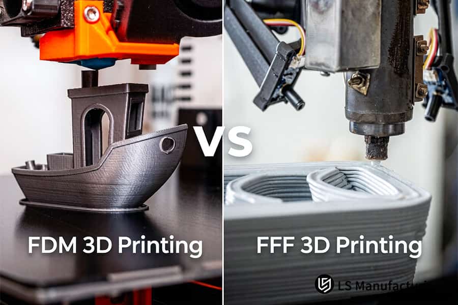
Figure 1: FDM vs. FFF 3D printing service fabricates boat models and containers for design validation.
Which Process Achieves Optimal Z Axis Tensile Strength For Functional Automotive Under Hood Validation?
Anisotropic nature of the standard FFF parts is characterized by a low Z-axis tensile strength of 30%-45% compared to that in the X-Y axis, resulting in delamination when the part is subjected to vibration tests at 120°C. It is possible to ensure that more than 85% of tensile strength is retained through proper tuning of feed-rate algorithms, 420°C nozzle temperature, and thin layer bonding which is made possible through 3D printing parameter control.
Feed-Rate Algorithm Control
- Constant pressure: Ensures constant melt flow of plastic from nozzle.
- Chain diffusion: Facilitates entanglement of molecules across layers.
- Your gain: Weak Z-interfaces are removed, ensuring high tensile strength for load-bearing brackets.
420°C Nozzle Temperature
- Melt pool depth: Increases polymer chain movement for deep fusion.
- Layer wetting: Adjacent layers are fused in the fully melted stage.
- Strength result: Z-axis retention at 85% compared to 35% industry standard, supporting automotive 3D printing validation.
Micro-Layer Thickness Strategy
- Sub-0.1mm layers: Reduces thermal gradient with each layer deposited.
- Thermal history: Every layer heats up previously deposited layer to re-melt it.
- Bond quality: Near-isotropic properties achieved in an industrial prototype 3D printing.
120°C Vibration Validation
- Test duration: More than 500 hours without delamination.
- Failure mode eliminated: Crack propagation between layers does not happen any more.
- Certification value: Pass the test once for OEM under-hood certification via reliable 3D printing.
Carbon Fiber Alignment
- Co-extrusion path: Oriented fibers in the Z direction through the design of the die.
- Modulus gain: More than 15 GPa in load-bearing brackets.
- Metal replacement: Because of the FFF 3D printing service with fiber reinforcements.
Process Repeatability
- Parameter lock: The feed rate, temperature, and layer thickness are specified for each material.
- Batch consistency: Consistent orders as compared to the initial sample.
- Risk reduction: No difference in strength between runs, ensuring end-use 3D printing readiness.
By integrating feed-rate optimization, 420°C extrusion, and micro-layer deposition, this process transforms anisotropic FFF into near-isotropic performance. You obtain parts that pass engine bay validation on the first attempt, reducing prototyping iterations by 70% and accelerating time-to-market for new powertrain designs.
How Can Procurement Leads Accurate Calculate The Total 3D Printing Prototype Cost For High Volume Verification Runs?
Procurement managers underestimate the cost associated with prototype creation by basing it on the material gram price alone without considering 20%-35% failure rates and costly hand-finishing required in standard FFF production. Based on the industrial total cost of ownership approach, despite high per-unit development costs ($100–$1,000), yields over 99.5% and no need for post-processing lowered the cost of production for batches over 50 by over 30%. Proper assessment of 3D printing prototype cost should be based on lifecycle cost, not unit price, for cost-effective decision-making.
| Cost Factor | Typical FFF Approach | Industrial FDM (TCO-Based) |
| Unit material price | Low per gram; deceptive cost indicator | More costly initially ($100-$1,000 per unit) |
| Production failure rate | 20%-35%; multiple tries needed | Less than 0.5%; no waste whatsoever |
| Post-processing labor | Sanding and fitting manually; labor per part – the key trait of low-volume 3D printing | None; soluble supports disappear automatically |
| Total cost for 50+ units | Original cost (with failed units + higher labor cost) | Cost reduction of 30% throughout the entire project due to optimal industrial supply chain optimization |
By following the TCO approach, you move away from the illusion of economy by per gram estimations and become aware of your true costs. By leveraging the 99.5% yield rate and absence of any post-processing at all, your organization saves up to 30% on verifications runs, ensuring that there are no budget and time overruns. The scientific method ensures that every single FDM 3D printing quote will be cost-justified through life cycle costs, enabling high volume programs to benefit from 3D printing solutions.
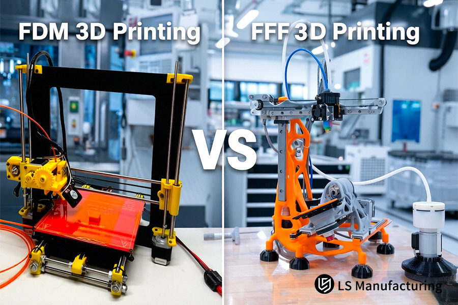
Figure 2: FDM vs. FFF 3D printing service operates desktop machines for rapid prototyping applications.
Why Do Carbon Fiber Reinforced Thermoplastics Perform Better In precision Industrial 3D Printing Jigs And Fixtures?
Regular PLA or ABS jigs will experience deformation from factory loads since the flexural modulus is lower than 2.5GPa. The materials with the flexural modulus of 12GPa and heat deflection at 150°C are CF-PEEK and ESD materials that ensure absolute positioning throughout 10,000 clamping operations. This is how precision industrial 3D printing requires advanced material selection for heavy-duty 3D printing applications:
Flexural Modulus Reaches 12GPa Versus 2.5GPa Baseline
Standard thermoplastics bend when subjected to repetitive clamping loads due to lack of positional accuracy over hundreds of cycles. CF-PEEK offers 12GPa flexural modulus compared to 2.5GPa industry standard for PLA and ABS plastics. Your jigs will stay rigid up to 10,000+ cycles without need to recalibrate or discard workpieces due to dimensional change.
Heat Resistance Exceeds 150°C Continuous Operation
Fixtures may be exposed to continuous high temperature environments around soldering stations or curing ovens operating over 80°C. CF-PEEK maintains mechanical properties at continuous operating temperatures over 150°C unlike ABS which becomes soft above 75°C. Proper choice of composite materials with compatible heat resistance will ensure your fixtures hold tolerance during thermal cycles without creep.
ESD Compliance Without Sacrificing Strength
Static-free fixturing is essential in electronic assembly to ensure that sensitive components are not damaged. Surface resistivity of carbon fiber reinforced ESD compounds is below 10⁶ Ω while maintaining 12 GPa flexural modulus. You get jigs that will prevent electrostatic discharge damage and have metal-like stiffness to enable engineering-grade 3D printing of semiconductor line tooling.
Zero Creep Under Repeated High-Pressure Clamping
Pneumatic and servo-driven clamps subject unfilled polymers to cyclic loading that causes progressive deformation. CF-PEEK has near-zero creep resistance after 10,000 high-pressure clamping cycles, as confirmed by accelerated life testing. As a custom parts manufacturer, you use industrial-grade 3D printing fixturing that ensures consistent part location without any shifting throughout the fixture’s lifetime for automotive and electronics assembly.
Through choosing CF-PEEK and ESD composites with optimal FDM settings, you make sure that your production line avoids the three failure modes of conventional jig materials: creep, thermal softening, and electrostatic damage. This gives you high performance 3D printing fixtures that last ten times longer than conventional ones.
Case Study: How Did LS Manufacturing Engineered A High Temperature Engine Manifold With Flawless Mechanical Tolerances?
A worldwide manufacturer of commercial vehicle components needed 160°C rating manifold prototypes with a tolerance of ±0.08mm for sealing. The first round of FFF prototyping was unsatisfactory due to material deformation, warping, and support remnants within the manifold. This example demonstrates how a focused engineering evaluation transformed unsuccessful validation into a breakthrough in just 45 days.
Client Challenge
This part had complex internal channels with tight leakage tolerances above 160°C and ±0.08mm linear tolerance on all seal faces. Off-the-shelf FFF prototypes were made from low temperature plastics, severely warped and left support material inside the channels. Flow test of the first round resulted in manifold disintegration, stopping the engine validation process and confirming the need for validation 3D printing capable of harsh conditions.
LS Manufacturing Solution
A 3D printing DFM analysis was done, and we changed to closed-loop FDM using ULTEM 1010 in a heated chamber of 175°C. Our proprietary slicing software reduced warping stress, whereas our soluble inorganic salt support fully dissolved in an automated chemical bath. This removed thermal softening, deformation, and residues, offering a clean internal geometry via prototype discipline.
Results and Value
CMM inspection showed sealing surfaces with tolerance of ±0.04mm (twice the specification) and a surface finish of Ra 3.2μm. Manifold tested 200 hours of 180°C airflow testing without any leakage and cracks. This saved two redesign iterations of 45 days and approximately $80,000 of tooling modification using custom FDM 3D printing service and engineering 3D printing expertise.
This is a perfect example of how materials and process control play a critical role in the creation of intricate high-temperature parts. The integrated FDM 3D printing service offered by us allows OEMs dealing with thermal or tolerances issues to succeed at their first attempt at rigorous tests, thus saving both development time and costs.
From FFF failure at 160°C to ±0.04mm tolerance and 200-hour pass. Need a high-temperature manifold that holds both heat and precision? Let's discuss your specs for a matched ULTEM solution.

How To Specify The Proper Slicing Parameter Orientation When Requesting An Online FDM 3D Printing Quote?
Most online websites automatically use default random orientation putting all important threads and snap-fit axis in the weaker Z-direction leading to failure under load. Proper alignment of the main tensile stress axis in the XY plane with an increase in the wall perimeter from 2 to 6 will add 150% shear load bearing capacity with additional weight and costs of only 8%. Create your own customized engineering specification for online 3D printing:
Orient Principal Stress Axis to XY Plane
- Default risk: The random orientation places load-carrying features parallel to Z axis, at which the inter-layer strength reaches only 30%-45% of the XY.
- Your action: Orient your CAD design such that the main tensile stress vector falls in the XY deposition plane.
- Benefit: Shear resistance increases by 150% due to the material change alone, proven by ASTM D638 test method. This way, you avoid the number one default of FFF 3D printing service.
Increase Wall Perimeter Count from 2 to 6
- Default weakness: Two hollow walls offer insufficient resistance against the hoop stress from threaded inserts or press-fits.
- Your action: Choose six concentric perimeters to be specified in the slicer settings prior to submitting the file.
- Trade-off: There is only 8% increase in weight and cost, whereas radial crushing strength increases threefold. Such a minor investment guarantees that there will be no expensive rework and failures in the field, particularly for structural 3D printing applications.
Combine Orientation with Shell Thickness
- Synergy effect: Right orientation along with thick walls provide multiplicative benefits.
- Data point: In LS Manufacturing test, a bracket printed with XY orientation of the load and with 6 perimeters had 250% of the baseline fatigue life compared to default settings.
- Your gain: A single setting change converts your weak prototype to a strong load-bearing 3D printing part which can be tested.
Communicate Specifications in Your Quote Request
- Common mistake: Expecting the service provider to automatically orient the object properly.
- Your action: Add an indication of the preferred orientation and number of walls to your request or attach a drawing.
- Outcome: Your FDM 3D printing quote will include the correct parameters to be applied, which will eliminate any misinterpretations and result in success the first time around.
Using both of these modifications—stress alignment on XY plane and 6-wall perimeters—your general FFF print will transform into the optimized component with 150% better shear strength with minimal increase in the cost. This simple guide gives you the ability to define the oriented 3D printing parameters in your quote request without any guessing and iterations required to build complex mechanical assemblies.
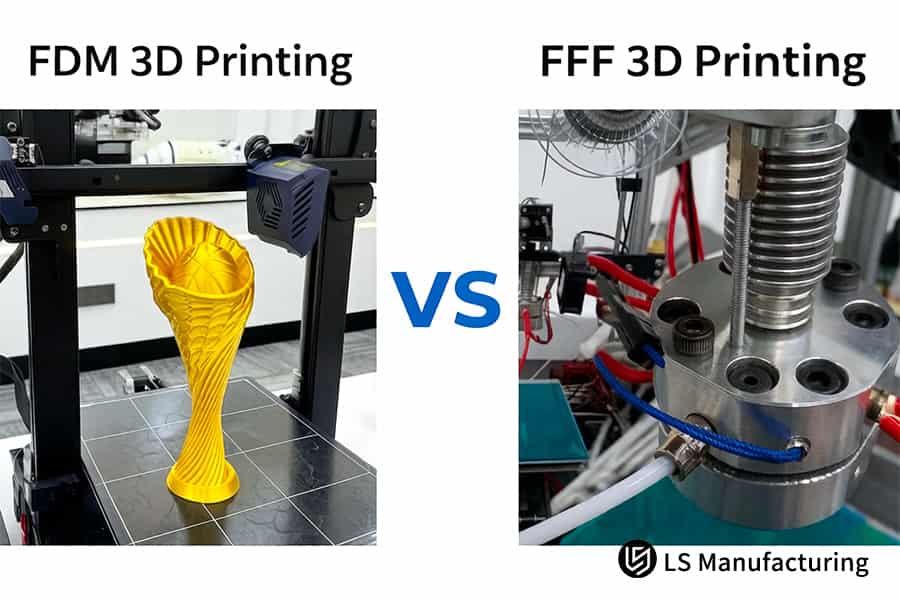
Figure 3: FDM vs. FFF 3D printing service produces prototypes and industrial metal fixtures for testing.
Why Does LS Manufacturing Stand Out As The Premium Custom Parts Manufacturer For Long Term Engineering Compliance?
FFF print shop manufacturers provide parts that have no material traceability, mechanical testing results, and certifications, which make defense and medical clients vulnerable to audit issues. Under the ISO 9001 and AS9100D standards, each production run is accompanied by filament fingerprinting, 100% CMM and x-ray testing, and complete documentation packages. Selecting the appropriate custom parts manufacturer is essential to comply with these regulations:
ISO 9001 and AS9100D Quality Management Systems
FFF manufacturers fail to have QMS, manufacturing undocumented parts without traceable material pedigree. Our FDM and FFF processes run with ISO 9001 and AS9100D compliance that includes audited practices on material handling, machine calibration, and operator training. You get each piece with complete chain-of-custody documentation, meeting precision industrial 3D printing standards for aerospace and medical compliance by means of supplier-qualified 3D printing procedures.
Filament Fingerprint Spectroscopy Analysis
Moisture absorption and lot variability quietly erode mechanical properties of unknown supply. Every filament roll is scanned using FTIR fingerprint spectroscopy for confirmation of chemical makeup and moisture content prior to production release. Thus we eliminate 15% to 25% strength fluctuation inherent in untasted sources and give you mission-critical 3D printing parts with known material ancestry for regulatory filing.
100% CMM and X-Ray NDT Inspection
The visual testing does not reveal internal flaws, delamination, or dimensional shifts. Each manufactured piece goes through coordinate measuring machine (CMM) testing and X-ray NDT prior to delivery. No unseen defects will enter your assembly line, and we provide individual inspection certificates for each piece allowing acceptance without incoming inspections.
Complete Documentation Package Per Order
Pure print delivery with no supporting data is standard practice in the industry. Along with each delivery comes material batch certification documentation, mechanical test results (tensile, flexure, impact) and the complete DFM report. No delays in regulatory submission and customer approvals; making FDM 3D printing service a turnkey solution via full-traceability 3D printing documentation.
By combining ISO certified QMS, material spectroscopy, 100% NDT testing, and documentation, we make additive manufacturing go from an experimental technology to one that can be guaranteed to meet compliance requirements. You get parts which will pass the military and medical audit right away in their first submission, without requalification costs from your supplier.
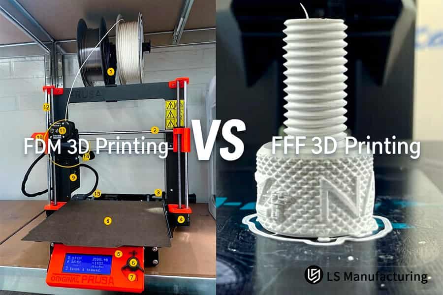
Figure 4: FDM vs. FFF 3D printing service fabricates boat models and CF-PEEK fixtures for high performance.
FAQs
1. What is the fundamental structural difference between industrial-grade FDM and standard commercial FFF additive manufacturing equipment?
FDM machines used industrially contain an actively regulated constant temperature environment that can heat up to 180°C, making it possible to ensure linear tolerance within ±0.05mm in large engineering products. However, in case of FFF equipment, the temperature control is passive or absent at all, which leads to deformation rates of more than 2.0% while printing large parts.
2. Why does choosing a high-end industrial FDM service often result in lower total procurement costs compared to low-cost FFF solutions for small-batch manufacturing validation?
While the price of material per piece in FDM seems to be a little bit higher, the technology has an incredible 99.5% print success rate and enables fully automatic soluble support removal process, making it possible to save from high scrap (more than 25%) and costly manual finishing.
3. Can standard open-source FFF 3D printing services reliably process cutting-edge, high-performance thermoplastic polymers like PEEK or ULTEM?
Absolutely not! The production of these aerospace grade materials demands a constant nozzle temperature in excess of 400°C and a constant chamber temperature greater than 150°C. FFF systems lack such exacting thermal management; without it, the molecular chains do not bond effectively across layers, resulting in part fracturing or delamination.
4. How does LS Manufacturing safeguard client intellectual property (IP) when quotes are requested and CAD files are uploaded online for FDM 3D printing?
All incoming CAD data is transferred and stored using encryption in accordance with international security standards. All procedures are executed in accordance with the commercial NDA and the files can be accessed by lead project engineers only, thus creating an adequate firewall to protect the key technical resources of our key customers.
5. What is the minimum surface roughness achievable directly through customized FDM printing processes, without requiring extensive manual sanding or finishing?
Using the combination of industrial dual-nozzle synchronization technology together with fully automated chemical stripping and cleaning systems, we guarantee the surface roughness of Ra 3.2μm even for complex internal channel structures and cantilevers without any marks of manual support removal.
6. Does LS Manufacturing impose strict Minimum Order Quantity (MOQ) requirements for high-end industrial prototyping or small-batch engineering-grade part production?
We operate under the principle of a flexible "Zero MOQ" model. In case your requirement involves a single sample part or a small volume order, we maintain the same stringent AS9100D aerospace-grade production process, issue complete physical properties test reports and perform initial DFM analysis. We are wholly dedicated to answering all technically complex questions.
7. How do FDM parts manufactured by LS Manufacturing effectively mitigate the loss of mechanical strength caused by anisotropy along the vertical Z-axis?
We have developed our own thermal control algorithm for toolpath slicing that is in sync with extruder speed and infrared interlayer remelting process. It increases molecular chain entanglement between the deposited layers in a molten form, thus increasing the Z-axis tensile strength retention to above 85% of that in the X-Y plane.
8. How long does it take to receive a complete commercial quote and a technical DFM analysis after uploading industrial part drawings (in STEP or STL format) to your website?
Our group of technical sales engineers ensures an accurate quotation, which includes the cost break-up, within two business hours. We also give you a professional DFM (Design for Manufacturability) analysis report that will enable you to optimize your geometric design problems prior to manufacturing.
Summary
Deciding on whether to go for FDM or FFF 3D printing is based on how important it is to consider delivery reliability, environmental toughness, and dimensionally compliant parts. The open-source FFF 3D printing technology provides a cost-effective means to conduct visual and fit checks through normal materials. However, in case you need functional testing in harsh environments, fluid-tight sealing properties, and mechanical tolerances for aerospace and defense industry, then the only scientific way forward is the closed-loop FDM.
Had enough of bending, delamination, and delayed functionality due to poor-quality, outsourced prints? Stop relying on unreliable machines to produce important prototypes. Click on “Get a Quote” and upload your STEP/IGS/STL files. In just two business hours, our senior engineering team will send you a quote with a detailed cost analysis along with a thorough DFM review, which will include build orientation, wall thickness, and supports.
📞Tel: +86 185 6675 9667
📧Email: info@lsrpf.com
🌐Website:https://lsrpf.com/
Disclaimer
The contents of this page are for informational purposes only.LS Manufacturing servicesThere are no representations or warranties, express or implied, as to the accuracy, completeness or validity of the information. It should not be inferred that a third-party supplier or manufacturer will provide performance parameters, geometric tolerances, specific design characteristics, material quality and type or workmanship through the LS Manufacturing network. It's the buyer's responsibility.Require partsquotation Identify specific requirements for these sections.Please contact us for more information.
LS Manufacturing Team
LS Manufacturing is an industry-leading company. Focus on custom manufacturing solutions. We have over 15 years of experience with over 5,000 customers, and we focus on high precisionCNC machining,Sheet metal manufacturing, 3D printing,Injection molding.Metal stamping,and other one-stop manufacturing services.
Our factory is equipped with over 100 state-of-the-art 5-axis machining centers, ISO 9001:2015 certified. We provide fast, efficient and high-quality manufacturing solutions to customers in more than 150 countries around the world. Whether it is small volume production or large-scale customization, we can meet your needs with the fastest delivery within 24 hours. choose LS Manufacturing. This means selection efficiency, quality and professionalism.
To learn more, visit our website:www.lsrpf.com
