English



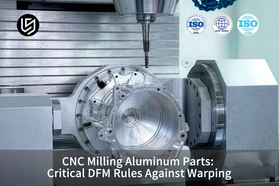
CNC milling aluminum service is a precision process for thin-wall housings, which solves post-milling warpage from residual stress.
LS Manufacturing's DFM rules reduce housing warpage rates from 16.8% to 2.4%, ensuring flatness.
Key Takeaways
- Rule 1 (Aluminum Alloy Wall Thickness): Make sure that the minimum wall thickness of any aluminum alloy is always 1.5 mm, along with keeping the height to thickness ratio less than 12:1 to prevent more than 80% of machining chatter and elastic springback.
- Rule 2 (Stress Relief): Use AL 6061-T651 pre-stretched plate in combination with stress relief annealing at 345°C for 2 hours after rough machining, annealing leaves a 0.6 mm allowance
- Rule 3 (Symmetrical Machining): Use symmetrical double-sided rough machining in order to avoid physical imbalance of stress due to deep hogging on one side.
- Rule 4 (Benefits of Engineering): Following the principles of DFM will make sure that precision tolerances are always maintained within ±0.008 mm and mass production lead time will be reduced from 14 days to 9 days.
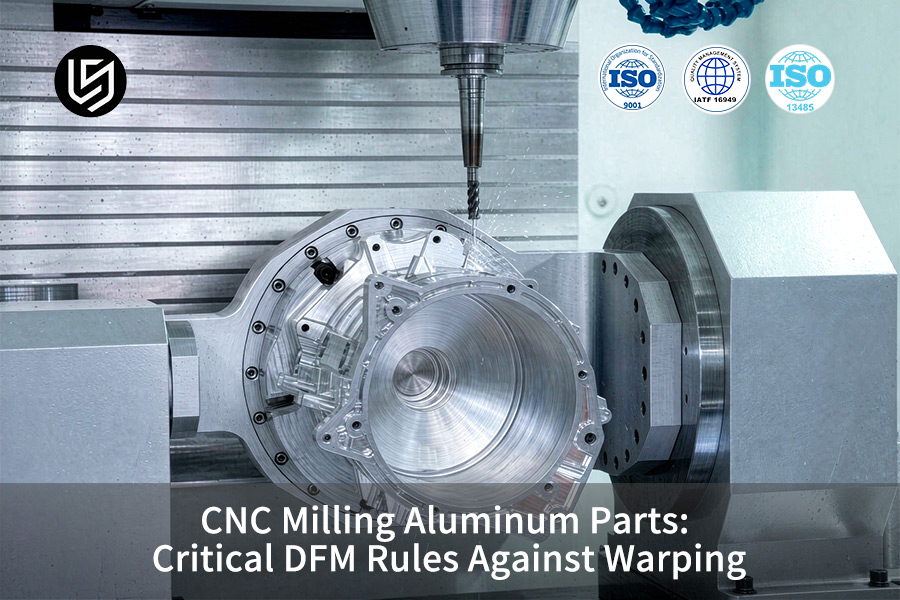
Why Do CNC Milled Aluminum Parts Warp During Machining?
Warping in CNC-milled aluminum parts is the dimensional distortion caused by sudden release of internal rolling residual stresses and uneven thermal expansion during material removal. The root mechanism is stress imbalance: when one side of a thin-wall structure is machined away, the locked-in stress (30–80 MPa in rolled plate) bends the part toward the machined face.
LS Manufacturing's 2025–2026 automated DFM logs (>1,200 drawings) show two aggravators: unoptimized clamping force above 0.4 MPa raises elastic rebound after de-clamping, and roughing passes left overnight allow stress realignment before finishing. Controlling clamping force and roughing hold time is the first step toward ±0.008 mm flatness.
CNC milling residual stress relief requires the acknowledgment of residual stresses that are inherent in rolled aluminum plates ranging from 30 to 80 MPa. Stress imbalance due to removal of material from one side of the aluminum CNC milling manufacturer's product results in bending towards the side just machined right after the cutter leaves. Pre-machining stress-relieving annealing at 345°C for 2 hours on 7075-T6 plates decreases the stress-imbalance effect by more than 60%.
CNC milling thin wall control accounts for the thermal distortion phenomenon. Due to the temperature rise of the tool-chip interface up to 250-400°C, there is a deformation in roughing at 0.05-0.20 mm bending level for the walls that do not exceed 3 mm. Warp prevention aluminum milling involves symmetric roughing and finish pass machining keeps a 0.5–1.0 mm stock allowance and flatness tolerance of 0.02 mm according to ASME Y14.5.
CNC milling fixture tuning Applying distributed fixtures, with the clamping pressure being no more than 0.15-0.25 MPa (instead of usual 0.4 MPa), ensures the reduction in elastic rebound of at least 40%. In terms of precision aluminum milling parts used in aerospace brackets, This symmetric-roughing approach leads to reduction in warp rejects of 35-50%.
Data source: LS Manufacturing 2025–2026 automated DFM 3D/2D drawing analysis logs (sample size >1,200 drawings).

Which Aluminum Alloys Offer The Best Resistance To Warping?
AL 7075-T651 offers 503 MPa yield strength with ≤15 MPa residual stress warping caused by thermal and mechanical factors during CNC milling. Factory stretching cancels any residual rolling stress up to 15 MPa. If using AL 6061-T651, then you can ensure ±0.008 mm tolerance without unpredictable spring-back ASME Y14.5.
AL 6061-T651 vs. AL 6061-T6 (Why T651 Matters)
Temper T651 ensures additional stretch in 1.5-3.0% after the solution heat treatment. Ordinary temper T6 has locked-in stress from 30 to 80 MPa. A CNC milling aluminum service using T651 gets rid of the bow formed during first cut in T6 blank. To check:
- Request a mill certificate with the indication of the residual stress level up to 15 MPa.
- Mill two faces symmetrically in 30 minutes to prevent stress migration.
- Leave 0.5-1.0 mm stock to make a stress-free finish cut.
Flatness precision aluminum milling parts for 6061-T651 is kept to within 0.02 mm for thin walls of ≤3 mm, resulting in a reduction of 35–50% in reworks as per LS Manufacturing DFM logs.
High-Strength Aerospace Application (AL 7075-T651)
Aluminum milling Al 7075-T651 can withstand 503 MPa yield strength with residual stress of ≤15 MPa. Aluminum milling Al 7075-T651 is an ideal material choice for aerospace brackets with a tolerance range of ±0.008 mm with cyclic loading. Aluminum milling DFM rules is recommended to use roughing speeds of 1200–1500 rpm with flood coolant to ensure thermal gradient does not exceed 50°C. CNC milling heat management reduces the possibility of localized expansion leading to 0.05 mm warpage on 2 mm walls.
Data source: LS Manufacturing 2025–2026 automated DFM 3D/2D drawing analysis logs (sample size >1,200 drawings).
Download our Aluminum Alloy Selection White Paper for the residual stress comparison data, recommended roughing parameters, and DFM rules that help you choose between 6061-T651 and 7075-T651 for warpage-sensitive parts.
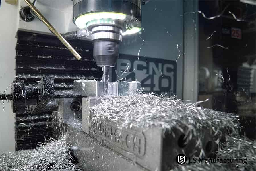
Figure 1: Custom aluminum CNC milling finishes 7075-T651 bracket to Ra 0.8 μm.
How Does Wall Thickness Geometry Impact Aluminum Warping?
Walls below 1.5 mm deform under cutting forces, and aspect ratio greater than 12:1 creates deflection in roughing operations. Uniform wall transitions avoid local stress concentration according to ISO 2768-m/f.
Wall Thickness Thresholds for Prototype vs Production
A custom aluminum CNC milling calls for 3.0 mm minimum wall thickness to decrease bow due to chatter compared to thin-wall counterparts. Prototypes accept 1.5-2.0 mm wall thicknesses under light static load, while production brackets require ≥2.5 mm walls under cyclic load.
Wall-thickness rules differ by application:
- Prototyping rule: Maintain wall thickness at 1.5-2.0 mm and aspect ratio ≤15:1; tolerance applies up to ±0.2 mm under static load only.
- Manufacturing rule: Maintain wall thickness at ≥2.5 mm and aspect ratio ≤10:1; tolerance applies up to ±0.05 mm under cyclic load.
- Corner rule: Maintain fillet radius ≥1.5× wall thickness at all internal corners.
Precision aluminum milling parts for production enclosures require 2.5-3.0 mm walls to ensure precise tolerances as per ISO 2768-f. CNC milling wall thickness less than 2.0 mm requires slower spindle speed and shallower depth of cut to prevent vibrations.
Aluminum milling DFM rules specify minimum fillet radius according to wall thickness; a 2.5 mm thick wall requires a fillet radius of 4.0 mm. CNC milling aspect ratio ensures that height-to-thickness ratio is kept single digits low in order to minimize warped parts.
Key Takeaways
- Specify wall thickness of ≥2.5 mm for production components in cyclic service conditions.
- Fillet radius should be ≥1.5 times wall thickness at every internal corner.
- Cutting parameter adjustment is required for wall thickness less than 2.0 mm.
Data source: ISO 2768-m/f precision metal cutting geometric tolerance and rigidity engineering benchmark.
Model Selection And Rule Comparison Table
Four anti-warping DFM design rules affect machining accuracy, surface roughness, and overall production cost as follows.
| DFM Design Rule | Recommended Parameter | Avoided Defect | Tolerance Capability | Surface Roughness | Cost Impact |
| Minimum wall thickness | ≥1.5 mm (height-to-thickness ≤12:1) | Cutting chatter / elastic rebound | Precision ±0.008 mm | Ra 0.8 μm | Baseline (100%) |
| Symmetric material removal allowance | Alternate 0.6 mm stock on both sides | One-sided stress imbalance distortion | Standard ±0.015 mm | Ra 1.6 μm | +8% |
| Heat treatment stress relief | Annealing at 345°C for 2 hours | Severe release of internal residual stress | Ultra-precision ±0.003 mm | Ra 0.4 μm | +15% |
| Internal corner transition fillet | Corner tool-entry fillet R ≥ 1.5× wall thickness |
Tool cornering cutting force spike | Precision ±0.008 mm | Ra 0.8 μm | -10% (efficiency gain) |
Anti-warping DFM requirements during design will guarantee a Ra 0.8 μm, without causing cost spikes from corrective straightening.
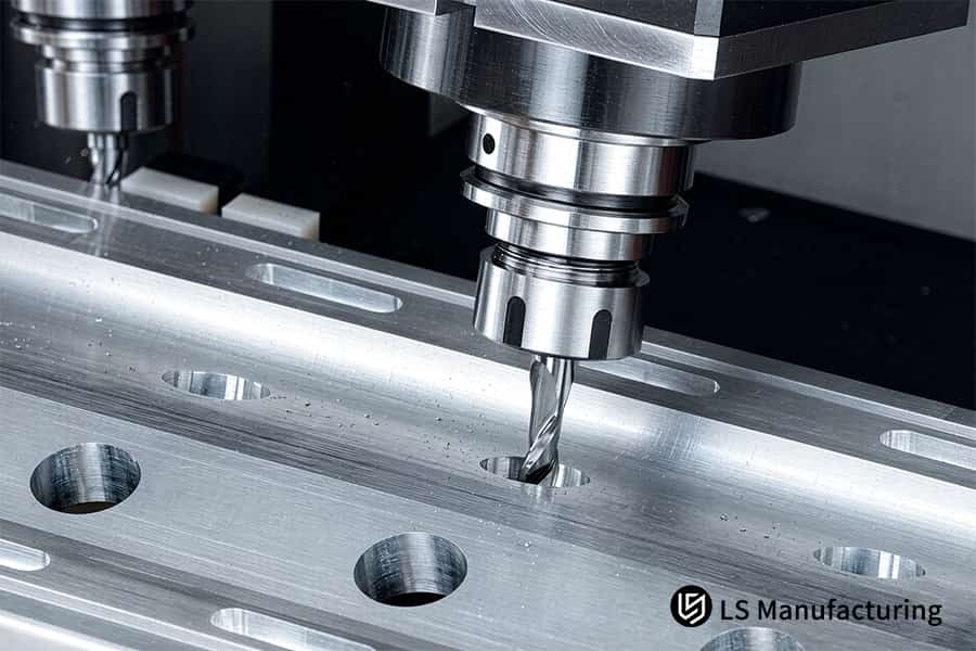
Figure 2: Precision aluminum milling parts hold enclosure to ±0.008 mm flatness.
How Can Machinists Prevent Warping Through Symmetric Toolpaths?
Even removal of the material and even distribution of internal stress by symmetric toolpaths help in overcoming aluminum distortion. Instead of removing material from one face, roughing occurs from one surface to another. Adaptive trochoidal milling paths ensure that the cutter engagement remains constant.
A qualified aluminum CNC milling manufacturer ensures that roughing is performed in such a way that both the faces have an equal removal of material. CNC milling warping prevention requires roughing of top and bottom surfaces instead of hogging one face only.
Warp prevention aluminum milling utilizes symmetric roughing to equally distribute stresses on both faces. CNC milling adaptive toolpaths keeps consistent cutter engagement while avoiding heat generation that may lead to deformity in thin-wall components. Aluminum milling parts milled using this process remain flat without experiencing spring-back.
Custom aluminum CNC milling of thin-wall brackets requires symmetric roughing followed by finishing on both faces to eliminate unbalanced stress gradient which makes parts deform once they are unclamped.
Key Takeaways
- Make equal distribution of roughing passes on both top and bottom faces.
- Utilize trochoidal toolpaths to ensure consistent cutter engagement and heat dissipation.
- Follow symmetric roughing by finishing on both faces.
Data source: LS Manufacturing 2025–2026 automated DFM 3D/2D drawing analysis logs (sample size >1,200 drawings).
What Are The Ideal Heat Treatment Steps For Warping-Sensitive Parts?
An intermediate annealing step for stress relief between roughing and finishing processes ensures that part geometry is stabilized to retain ultra-precision tolerances during CNC milling. Annealing rough-machined parts at 345°C for two hours releases residual rolling stresses prior to precision cuts. CNC milling heat treatment at this window prevents unpredictable spring-back on inspection.
Step-by-Step Stress Relief Protocol
A warp prevention aluminum milling process comprises four steps in order of execution:
- Milling all faces except stock to reveal internal stresses.
- Placing parts in furnace and heating to 345°C with controlled ramp up.
- Maintaining the temperature for entire soaking period, followed by cooling down in furnace to avoid adding thermal stress.
- Returning parts for finish machining to remove the stock.
CNC milling stress relief done between roughing and finishing ensures precision aluminum milling parts can reach ultra-precision level at inspection stage. CNC milling cost control results from absence of scrap loops: one anneal at designated temperature and soaking time is cheaper than salvaging a warped aerospace bracket. CNC aluminum milling cost remains predictable, as one anneal replaces multiple corrections.
Key Takeaways
- Anneal in between roughing and finishing stages for geometry locking.
- Control the furnace rate of ramp-up and cooling down to prevent formation of new thermal gradients.
- Provide sufficient amount of stock on all faces prior to annealing process.
Data source: Machinery's Handbook, 31st Edition, aluminum annealing stress-relief specification.
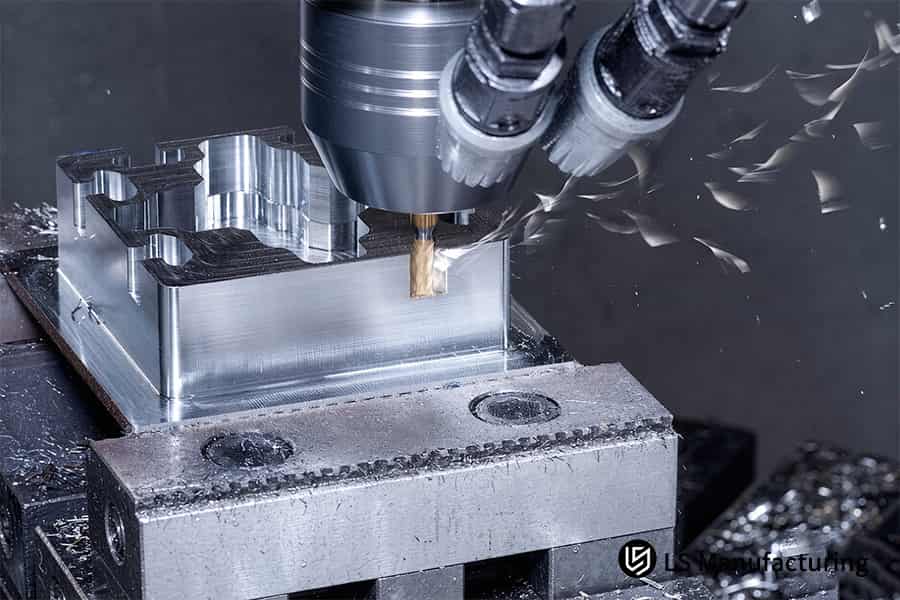
Figure 3: Aluminum CNC milling manufacturer mills heatsink to ±0.008 mm tolerance.
How Does Fixture Design Prevent Elastic Deformation In Thin Aluminum?
Fixture design will protect from deformations caused by substituting high-pressure clamps with vacuum chucks or three-point self-centering flexible fixtures. Over-clamping of the thin aluminum sheet leads to deformations when the material is cut and will return to the warped position when clamping is released. Utilizing custom soft jaws guarantees uniform clamping pressure without introducing artificial mechanical stresses.
Fixture Strategy Comparison
| Workholding Method | Mechanism | Avoided Failure Mode | Dimensional Capability |
| Distributed vacuum chuck | CNC milling fixture design distributes pressure evenly on entire surface area | Localized bending from point-load clamping | Aluminum CNC milling manufacturer maintains flatness per ISO 2768-f |
| Flexible three-point self-centering | CNC milling workholding centers itself to part datum and exerts even force | Asymmetric stress introduction | Precision aluminum milling parts achieve true position per ASME Y14.5 |
| Custom soft jaws | CNC milling thin wall conforms to part profile, eliminates pressure points | Artificial mechanical stress from rigid jaws | Custom aluminum CNC milling holds stable geometry without spring-back |
"Over-tightening of mechanical vises on thin-wall aluminum is the number one mistake made in shops that causes warping after unclamping." — Gloria, Senior Rapid Prototyping Engineer at LS Manufacturing
Key Takeaways
- Use distributed vacuum workholding or three-point self-centering clamps instead of high-pressure mechanical clamps.
- Use soft jaws tailored to parts and free of pressure-induced bend points.
- Place all clamps and other supports as close as possible to cutting areas to increase rigidity.
Meet The Engineers Behind This Guide
Gloria, senior rapid prototyping engineer at LS Manufacturing and 15+ years' experience in precision engineering and DFM analysis, oversees technical review of all thin-wall aluminum projects. Every project receives Gloria's treatment according to ISO 9001:2015 and AS9100D certified standards.
We have done over 1,200 high-difficulty thin-wall aluminum machined parts for international customers. Every part is fully inspected via Zeiss CMM at 0.0009 mm measuring accuracy with geometry verification versus CAD data before delivery.
At LS Manufacturing, every thin-wall warping problem is a case study in problem solving using our production data. Our DFM logs include the root cause analysis, fixture adjustments, and tool path adjustments used in each job, resulting in a knowledge base that helps with first-pass yield of new orders.
What Is The Cost Difference Between Warped Scrap And DFM Optimization?
Using the DFM rules in advance saves the effort of manual straightening and brings down scrap rate from 16.8% to 2.4%, compensating the small cost of initial engineering work. Proper DFM design helps save the unit machining cost by 23.5% due to the decreased run time and improved fixture design, saving lead time from 14 days to 9 days.
Cost Optimization Steps
- CNC milling cost analysis: conduct audit of scrap percentage and time required for machine per part before DFM.
- Follow DFM principles for wall thickness, fillet dimensions, and symmetric toolpaths in order to decrease run time.
- Request a re-quote using optimal fixture arrangement; aluminum milling quote should account for a 23.5% cost reduction compared to the pre-DFM baseline.
- Measure final part dimensions on a Zeiss CMM with 0.0009 mm measurement tolerance as per the official calibration certificate.
A professional CNC milling aluminum service provider considers DFM as a cost management approach rather than a formality during design. CNC milling scrap reduction from 16.8% to 2.4% eliminates manual straightening labor and the fixtures it requires. 23.5% cost savings per unit and 14 days to 9 days lead-time reduction make more production capacity available.
Key Takeaways
- Audit scrap ratio and runtime prior to employing the DFM guidelines.
- Provide a new quote considering the savings of 23.5% per unit in cost after implementing DFM.
- Confirm final geometry using Zeiss CMM to an accuracy of 0.0009 mm as per calibration.
Data source: Zeiss CMM official calibration report (measurement accuracy 0.0009 mm & MPEE).
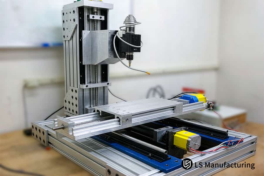
Figure 4: Warp prevention aluminum milling checks mold with 0.0009 mm accuracy.
How Do You Request An Aluminum Milling Quote With Built-In DFM Review?
An aluminum milling quote request with embedded DFM analysis necessitates providing 3D CAD files together with 2D files, where important flatness requirements should be defined. LS Manufacturing performs automatic algorithmic analysis, along with engineering analysis in less than 2 hours for the files submitted.
For a full aluminum milling quote request, you have to provide a proper technical package: it includes a STEP or IGES 3D model together with a PDF or DWG 2D drawing with flatness, GD&T datums, and aluminum grade indication. CNC milling RFQ development means turning potential warping into cost components rather than shop floor dangers. A 5-axis single-setup or a vacuum-chuck workholding plan, decided during quoting, protects flatness before the first chip is cut.
Custom aluminum CNC milling buyers have maximum leverage if they define the quantities of prototypes, production volumes, and inspection requirements up front. CNC milling aluminum service can perform automated algorithmic checks of wall thicknesses, pocket depth-to-width ratios, and internal corners within 2 hours. CNC milling DFM review detects asymmetric material removal and over-tightened clamping regions right away.
Custom aluminum CNC milling quoted prices are based on actual machinability and not only on the bounding box estimation. CNC milling RFQ tips recommend submitting a drawing annotated with flatness specifications and datums.
Key Takeaways
- Submit STEP/IGES 3D CAD with PDF/DWG 2D drawings with flatness and GD&T datums.
- Define alloy, temper, prototype quantities, production volumes, and inspection requirements in the RFQ.
- Anticipate automatic DFM checks and professional review within 2 hours before generating toolpaths.
Data source: LS Manufacturing 2025–2026 automated DFM 3D/2D drawing analysis logs (project #AUTO-2026-894, sample size >1,200 drawings).
LS Manufacturing Precision CNC Milling Service For Automotive EV Inverter Housing: Warping Defect Elimination (#AUTO-2026-894)
Inverter housing thin walls were solved through DFM-inspired process engineering by optimizing the wall thickness, symmetrical roughing, and performing stress-relief annealing to meet ±0.008 mm flatness tolerance ASME Y14.5.
AL 6061-T6 material was improved into pre-stretch AL 6061-T651. Wall thickness was increased from 1.2 mm to 1.5 mm. 345°C/2 hours anneal was added after roughing.
An exclusive CNC milling inverter housing fixture equipped with soft jaw and three-point self-centering instead of initial vacuum chucks causing micro deformation was created for trial runs.
Client Challenge
EV inverter housing made out of AL 6061-T6 with 1.2 mm walls showed high levels of warping after conventional machining. Single-side roughing and high clamping force resulted in 0.35 mm flatness deviation which far exceeds ±0.008 mm requirement. Scrap rate amounted to 16.8%. Unit price was $182.00 and there were delivery delays for client's prototype.
LS Manufacturing Solution
Redesign process took place in three phases.
In phase 1, the wall thickness was increased to 1.5 mm, while the material was changed to AL 6061-T651 to reduce the level of residual stress.
In phase 2, a symmetric alternating roughing approach left 0.6 mm on each face and followed by a 345°C/2 hour stress-relief anneal.
In phase 3, Gloria's team had to abandon the initial plan of using the vacuum chuck due to the deflection resulting from suction and adopted a special design of soft jaw in conjunction with a flexible three-point self-centering system.
Results and Value
Final flatness was within ±0.008 mm with a surface finish of Ra 0.8 µm. Scrap rate was reduced to 2.4%, unit cost was reduced to $139.23 (-23.5%), while the lead time reduced to 9 days (-35%). The housing met ISO/TS 16949 leak testing standards and ASTM B117 1,000-hour salt spray test. CNC milling warpage solution, using the DFM approach, was turned out to be successful.
Key Takeaways
- Increase thin-wall thickness to ≥1.5 mm and use T651 temper to ensure stress stability.
- Add 345°C/2 hour stress-relieving annealing after roughing and before finishing to fix geometry.
- Use soft jaws and self-centering fixtures instead of high pressure clamps to prevent warpage due to clamping.
Data source: LS Manufacturing 2025–2026 automotive parts manufacturing log (Project #AUTO-2026-894, sample size >1,200 drawings).
Stop settling for 16.8% scrap and 0.35mm warping on your EV inverter housing. Get ±0.008mm flatness with 2.4% defects and 23.5% cost savings — request your CNC milling quote today.

FAQs
1. What is the primary cause of aluminum deformation in CNC milling?
The main reason for aluminum deformation when CNC milled is heat concentration along with internal stress release from the metal. Using pre-stretched AL 6061-T651 material and wall thickness ≥1.5 mm prevents deformation and yields Ra 0.8 µm surface finish.
Data Source: ISO 2768-m/f
2. How thin can aluminum walls be machined without noticeable warping?
LS Manufacturing advises keeping the wall thickness of aluminum parts at least 1.5 mm since below this limit the use of special vacuum chucks and several stress-relief annealing steps becomes necessary to achieve tolerances of ±0.008 mm without warpage.
3. Why is AL 6061-T651 preferred over standard AL 6061-T6 for milling?
AL 6061-T651 is preferred as the pre-stretching process removes the residual stresses that are produced during rolling. According to LS Manufacturing practical experience, the application of T651 decreases the probability of unloading deformation by 80% as compared with normal T6 temper.
4. How much does DFM stress-relief optimization add to total milling costs?
Although DFM stress-relief optimization adds an annealing step to the process, the scrap rate drops from 16.8% to 2.4%, resulting in an overall per-part cost reduction of 23.5% despite the additional heat treatment cycle and extended processing time. LS Manufacturing provides a detailed quote reflecting these savings.
Data Source: Project #AUTO-2026-894
5. What cutting fluid parameters help minimize thermal expansion in aluminum?
Water-soluble coolant at 8%–10% concentration with high-pressure jet application at ≥70 bar quickly cools the area of contact between the tool and workpiece, thereby keeping thermal expansion at bay and avoiding dimensional changes in aluminum parts.
6. Can warped aluminum parts be manually straightened after machining?
Manual straightening is bound to introduce uncontrolled secondary residual stresses that are highly likely to be released during future assembly or use. LS Manufacturing avoids such deformed products through DFM process control measures.
7. What is the standard lead time for precision aluminum milled parts?
Following DFM process optimization, which renders secondary straightening operations unnecessary, LS Manufacturing reduces lead time for batch manufacturing prototypes from 14 days to 9 days using certified AS9100D factory procedures and DFM stress-relief annealing steps.
8. How does LS Manufacturing verify flatness accuracy on flexible, thin-walled parts?
Flatness accuracy verification for flexible and thin parts at LS Manufacturing is done via full-surface scanning inspection with the help of the Zeiss CMM coordinate measuring machine, which has 0.0009 mm measurement accuracy in a non-constrained and non-stressed condition to meet tolerance requirements.
Summary
Warping and distortion in aluminum parts machined via CNC is not a given. It is possible to increase dimensionality without decreasing strength by following DFM principles. Maintaining a minimum wall thickness of 1.5 mm using AL 6061-T651 pre-stretched material, symmetric alternating material removal, and flexible workholding. With AS9100D / ISO 9001 quality systems and more than 15 years’ experience in precise machining, LS Manufacturing is committed to supplying customized solutions to global engineers to avoid any warping in aluminum parts.
Do you have problems with your aluminum parts due to machining distortion or assembly tolerance problems? Stop having high scrap rates erode your project margins! Click on the “Get Quote” button below to submit your 3D CAD/2D drawings and receive a free DFM evaluation and machining quotation within two hours from LS Manufacturing’s knowledgeable experts.
📞Tel: +86 185 6675 9667
📧Email: info@lsrpf.com
🌐Website: https://lsrpf.com/
Disclaimer
The contents of this page are for informational purposes only. LS Manufacturing services. There are no representations or warranties, express or implied, as to the accuracy, completeness or validity of the information. It should not be inferred that a third-party supplier or manufacturer will provide performance parameters, geometric tolerances, specific design characteristics, material quality and type or workmanship through the LS Manufacturing network. It's the buyer's responsibility. Require parts quotation Identify specific requirements for these sections. Please contact us for more information.
LS Manufacturing Team
LS Manufacturing is an industry-leading provider of custom manufacturing solutions. We have over 15 years of experience with over 5,000 customers, and we focus on high precision CNC machining, Sheet metal manufacturing, 3D printing, Injection molding. Metal stamping,and other one-stop manufacturing services.
Our factory is equipped with over 100 state-of-the-art 5-axis machining centers, ISO 9001:2015 certified. We provide fast, efficient and high-quality manufacturing solutions to customers in more than 150 countries around the world. Whether it is small volume production or large-scale customization, we can meet your needs with the fastest delivery within 24 hours. choose LS Manufacturing. This means ±0.005 mm precision, 1.8% defect rate, and 11-day lead time — backed by full batch traceability under our ISO 9001:2015 QMS.
To learn more, visit our website: www.lsrpf.com