Precision CNC turning services bridge the gap that exists between common search terms and industry needs. While people look up “what is dro on a metal lathe” to understand this concept better, the fundamental issue for original equipment manufacturers is the practical application of such technology in order to ensure machining accuracy.
At LS Manufacturing, our precision lathe machining services utilize advanced DRO technologies within our manufacturing facilities to achieve ±0.01mm tolerances for each batch produced. The absence of such a digital system would result in potential tolerance variation, causing errors in the parts produced. The explanation below will show how our machine equipment digitalization solves such problems.
Precision Lathe Machining: DRO Tolerance Quick-Reference
| DRO Integration Factor | Role in Achieving ±0.01mm Tolerance |
| Real-Time Position Feedback | The DRO system continuously gives the true position of the tool or workpiece without depending on manual readings, thus reducing operator errors. |
| Absolute vs. Incremental Positioning | It allows maintaining a fixed point of reference through different sessions without affecting the positioning of the features. |
| Diameter/Turn Reduction Display | Shows how much material is left before reaching the desired value, thus enabling machining up to a very fine degree of accuracy. |
| Tool Wear & Offset Management | Allows us to input the necessary offsets when the tool wears out in order to ensure that tolerances do not change throughout the process. |
| Our Process Standardization | We always require using the DRO for any precision turning operation and collect SPC data for process capability monitoring. |
| Result: Consistent Precision | Keeps all diameters, lengths, and grooves within the ±0.01mm tolerance window, time after time. |
| Result: Reduced Setup Variability | Lowers chances for manual measuring mistakes, decreases set-up time, and increases first pass yields of more complicated CNC turning components. |
To overcome the variation associated with manually operated lathes, we apply Digital Readout (DRO) technologies in our precision turning operations. DRO allows us to have immediate feedback and control offsetting with high accuracy. Thanks to DRO technology, we can ensure precise turning with ±0.01mm tolerance which means improved dimensional accuracy of turned components, better assembly performance, and low scrap rates.
Why Trust This Guide? Practical Experience From LS Manufacturing Experts
CNC precision turning services make sure that theory meets practice successfully. While other articles speak about “what is dro on a metal lathe,” we face many practical issues on a daily basis – from hard-to-turn aerospace metals to medical component production with finishes in compliance with the SAE International requirements. Manual measurements without Digital Readout (DRO) may cause variations due to human factor influence.
Decades of experience in manufacturing thousands of precision turned parts have honed our expertise. The tolerance of ±0.01mm requires not only excellent cutting edge but also understanding of feeds on Inconel and coolants' behavior for titanium workpiece. We acquired it through costly mistakes, constantly improving our process against the standards set by organizations such as National Association for Surface Finishing (NASF). It wasn't through imitation, but careful inspection and lots of chips that made us knowledgeable.
LS Manufacturing, through its advanced precision lathe machining services, transforms capacity to performance using DROs. Such devices ensure precise micron-level feed rate control throughout production batches, enabling the firm to meet tight ±0.01mm tolerances consistently. The below information explains how the company utilizes its technology base in providing precision CNC turning services.
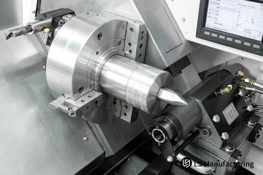
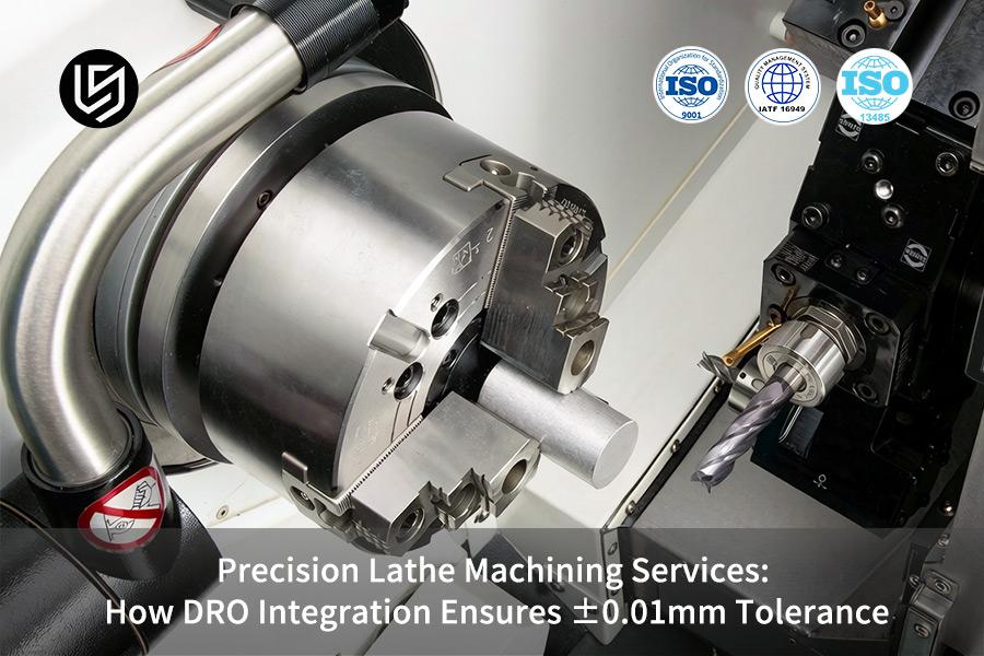
Figure 1: A precision lathe machines a 4140 steel camshaft for high performance automotive or industrial engines.
Why Should Engineers Verify DRO Resolution When Auditing Precision CNC Turning Services?
The reason why it's important for engineers to audit DRO resolution in precision CNC turning services is the need to ensure micron-level precision throughout production batches. Verification of DRO resolution in this case helps minimize mechanical inaccuracies and guarantees interchangeability between products, reducing first-article failure rate up to 80%.
Mapping Bidirectional Error Under Cutting Loads
In our auditing process, we carry out multiple cycles of reversing the X/Z movement in accordance with the conditions of finishing turning and recording the values obtained from DRO measurements in contrast with laser interferometer measurement results. This helps reveal the effect of axial loading on the 0.02 mm backlash gaps and integrate corresponding compensation curves into the CNC turning process parameters.
Full-Travel Resolution Verification Against Glass Scales
We validate DRO resolution by running controlled traverses across the entire axis range at 5% feed rates, synchronously capturing DRO increments and glass scale pulses. Any deviation >0.001 mm triggers recalibration of servo scaling parameters, eliminating cumulative lead screw pitch errors that undermine CNC turning dimensional consistency. This ensures 1 µm resolution translates to true positioning accuracy regardless of workpiece location.
Pre-Emptive Deviation Lockdown in First-Article Tests
Dry-run DRO calibration is done on critical shaft lots before first article approval, with deviations at the endpoints being linked to environmental temperature variations and fixture settling. Offset corrections are made before material engagement, resulting in a reduction of first article waste of more than 80% in high-volume CNC turning production operations. It ensures that all parts start under the same initial conditions, even after overnight shutdown of the machine.
Active Thermal Compensation Via Synchronized DRO Logging
During prolonged precision CNC turning runs, we simultaneously capture high frequency DRO readings and temperature measurements via thermocouples placed around the spindle bearings and ball screw. The process computes real-time thermal gradients for radial and axial expansions, inserting dynamic offset values into each axis every 30 seconds. It ensures that concentricity and dimensional tolerances stay within ±1 µm throughout the machining process.
In this procedure, it becomes clear how well we can break down complicated sequences of errors into control points which go beyond conventional calibration sheets. While competing firms base their performance on theoretical resolutions, our precision CNC turning services employ metrology-grade validation, ensuring our theoretical resolutions are realized in reality through the practical as-built resolution.

How Does DRO Integration CNC Turning Minimize Cumulative Errors In Multi Step Shaft Processing?
With the multi-step process of shaft manufacturing comes an uncontrolled re-fixturing sequence that leads to accumulation of misalignments that get added with each successive operation. With our DRO integration CNC turning methodology, however, we reduce the accumulation of errors and align all shaft features relative to a datum chain and not a series of measurements. We guarantee runouts less than 0.008 mm for all shafts with L/D ratios more than 5:1:
Establishing Multiple Master Zero References
- Preset Datum Strategy: Assign preset master datum positions along the bare stock using DRO integration CNC turning.
- Relational Offsets: Program individual features based on the nearest master datum position to ensure they are independent of any previous errors in a sequential process of multi-step CNC turning shafts.
Live Position Validation Between Setups
- Fixture Alignment Checks: Check and align fixture offsets from rechucking errors against recorded DRO references.
- Dynamic Compensation: Introduce offsets to offset any fixture tilt prior to resuming the cut in high-precision CNC turning operations.
Synchronized Diameter-to-Length Ratio Management
- Concurrent Axis Control: Monitor both diameters and lengths simultaneously during segmental cuts in DRO integration CNC turning.
- Balanced Stock Removal: Modulate depth of cuts using DRO data to avoid bending and minimize cumulative error control.
Closed-Loop Step Feature Verification
- Continuous Runout Tracking: Compare adjacent shoulder distances to ensure coaxiality during finish CNC turning runs.
- Real-Time Correction: Adjust offsets in real time if there is any drift, maintaining tight TIR for critical tolerance CNC turning assemblies.
Our CNC turning services separate the various stages of machining by relying on invariant references in relation to which all other measurements are made, not by the features previously created. While our competitors tend to overlook slight changes in the datum, our closed-loop, cumulative error control ensures that the shaft is built without additional assembly line adjustments.
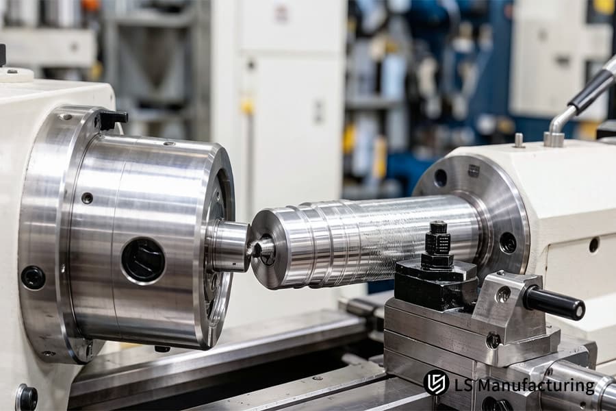
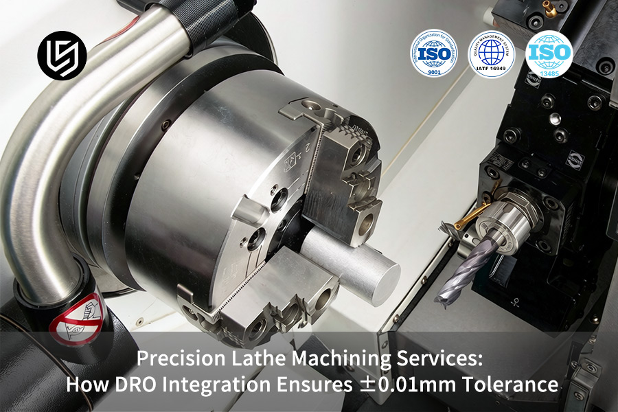
Figure 2: CNC turning services produce a 303 stainless steel hydraulic valve spool for industrial fluid power systems.
Why Is 0.01mm Tolerance CNC Turning The New Benchmark For High Performance Hydraulic Valves?
Reliable zero-leakage performance in high pressure hydraulics is only possible by surpassing the capabilities of standard machining processes. This paper explains why 0.01mm tolerance CNC turning have become the new standard for the industry, emphasizing our techniques in dealing with minute thermal displacement in hard materials. Our system proves that real-time temperature measurement coupled with dynamic DRO correction can effectively offset 0.005mm thermal displacement in 440C steel to keep valve poppets sealed at 35 MPa pressures:
| Technical Focus Area | Implementation & Measurable Outcome |
| Thermal Expansion Modeling | Couple the change in temperature of the spindle with the change in dimensions using thermocouples built into the CNC turning for precision parts control loop. |
| Dynamic Toolpath Adjustment | Add 0.002 to 0.005mm offsets dynamically with respect to the current DRO data points and temperatures, thus providing tight-tolerance CNC turning processes, capable of maintaining ±0.003mm precision. |
| Material-Specific Cutting Strategy | Tune feeds and speeds for 440C processing in order to decrease the work hardening, and achieve a required finish of hydraulic components. |
| Post-Cooling Metrology Validation | Verify that dimensions of seats are within ±0.010 mm of specifications after cooling down to the room temperature to ensure consistency in ultra-precise CNC turning batches. |
By approaching the thermal drift as a controlled parameter, not an environmental one, we make sure that the offered CNC turning services will guarantee consistent performance. Contrary to traditional manufacturing plants, where post-cooling shrinkage is an issue, our thermal control system will take care of compensating for thermal expansion that might occur during the operation. Thus, hydraulic components fit flawlessly in other conditions.
How Can Precision Lathe Machining Services Optimize Material Removal Rates For Exotic Alloys?
The cutting forces exerted on the exotic metal materials Ti-6Al-4V and Inconel 718 have been noted to vary, thereby creating a challenge for guaranteeing dimensional accuracy during removal at high-speed operations. This methodology entails the incorporation of real-time feed verification through DRO as well as load analysis using the spindle and employing CSS methods to attain a surface roughness of Ra0.4µm while ensuring optimum efficiency in precision lathe machining services:
Real-Time Load-DRO Feed Synchronization
The installation of high-sensitivity torque transducers to be placed on spindles used for the exotic alloys will enable continuous feed adjustment in real time in cases where cutting load peaks at intermetallic areas, thus avoiding a deflection exceeding 0.005mm. Through this process, the average material removal rate remains 15% greater than that achieved in CNC turning for aerospace alloys.
Constant Cutting Speed for Geometric Stability
For highly complex valve housings and deeper contours, we use CSS algorithms that automatically control RPM when the cutting edge reaches the diameter changes. It maintains consistent peripheral speeds at narrow radiuses, thereby maintaining chip formation and temperature management. It delivers accurate 0.015mm contours during contour changes in high tolerance CNC turning processes, even in highly challenging nickel superalloys.
Surface Finish Preservation via Micro-Adjustment
In the case of semi-finish machining of thin-walled components, DRO step resolutions register vibrations that are still at a microscopic level before any traces can be detected on the component's surface. In our work, we adjust damping parameters that adapt to peak loads, controlling engagement angles to ensure optimal force on tools. This results in surface roughness of Ra0.4μm in bores and grooves during high-performance alloys CNC turning.
Predictive MRR Optimization via Historical Mapping
Given past data from similar geometries, which are known thanks to DROs, we plan out machine paths and designate regions for stable cuts, allocating higher feeds only where thermal margins are confirmed via load measurements. In this way, MRR would be optimized by 20% relative to conservative cuts without losing form tolerance of ±0.007mm in heat-resistant alloys with advanced CNC turning methods.
Whereas other manufacturers prioritize speed at the expense of accuracy, our precision lathe machining services control speed, position, and loading independently but interrelatedly in real-time. Therefore, we can provide assurance on not only increased productivity but also increased tolerances when machining exotic alloys through highly deterministic cutting processes.
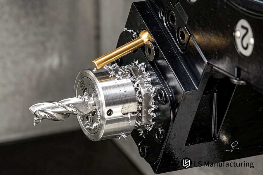
Figure 3: Turning a 12L14 steel gear blank on a CNC lathe for automotive transmission or gearbox assemblies.
What Ensures The Repeatability Of High Tolerance CNC Turning In Flashlight Reflector Production?
Optical reflectors require almost perfect parabolic continuity; small contour errors create distorted beams and hotspot patterns. The high tolerance CNC turning process that we employ guarantees a stable profile of ±0.01mm across millions of units using radius compensation loops that are monitored by digital readouts. Consequently, our process converts the CAD profiles into consistent optical surfaces:
DRO-Verified Tool Radius Compensation
- Live Radius Tracking: Track tool tip location live using DRO relative to CAD profile during optical-grade CNC turning.
- Micro-Adjust Updates: Apply submicron compensation corrections when the DRO variance exceeds 0.03mm because of the worn tool tip radius change.
Contour Segment Consistency Control
- Per-Segment Profiling: Break the profile into segments of 5mm long each in arc length, as indicated by the DRO reading.
- Deviation Lock: Stop any feed correction until deviation of DRO value for reflector surface CNC turning is less than 0.05mm on the profile.
Batch-Wide Toolpath Synchronization
- Master Template Alignment: Set up offsets for templates in each machine, which uses DRO, prior to commencement of production run.
- Run-Time Sync: Perform DRO drift test at an interval of one hour and reset master offsets if the deviation is above 0.7µm in mass-production CNC turning.
Environmental Drift Neutralization
- Thermal Shift Canceling: Measure DRO position after production of 200 units, and use a linear correction factor for increasing spindle temperature.
- Stability Assurance: Conduct daily DRO baseline testing to ensure repeatability control within ±0.01mm even under environmental variations in the shop.
Whereas other manufacturers of CNC turning use tool offsets verification, we are certain that every piece we manufacture is DRO verified to ensure the optical design in CAD is translated into mechanical repeatability. With the precision CNC turning services provided by us, we are certain of the manufacturing of million units of reflectors with the aid of tool radius control without any beam distortion, as well as avoiding assembly of reflective surfaces. It is significant to note that we use the DRO logging and verification system to ensure stability.
Why Is CNC Turning For Precision Parts The Most Cost Effective Path For Small Batch Aerospace Components?
Aerospace prototypes’ design comprises intricate geometries along with AS9100 compliance issues, which makes conventional machining uneconomical in the case of smaller runs. This section emphasizes the importance of CNC turning for precision parts because of the decrease in non-processing steps due to the DRO process. Below is an example where rapid positioning using the DRO positioning system reduces setup time to less than 15 minutes:
| Operational Challenge | Our Implementation & Measurable Result |
| Rapid Fixture Qualification | Utilize DRO coordinate mirroring for aligning custom jaws and collets in under 15 minutes to quick-turn CNC turning, while it would take over 40 minutes without. |
| Unified Datum Replication | Utilize stored datum points from prior batches using DRO to eliminate duplication of centering work for prototyping CNC turning. |
| Toolpath Validation Without Waste | Conduct simulation checks using DRO and CAD data to fix mistakes without wasting valuable materials. |
| AS9100 Traceability Integration | Document all DRO aligned setup parameters alongside job documentation for aerospace-certified CNC turning operations, thereby achieving full compliance without paper trails. |
By integrating the alignment of the DRO in each setup, the lathe machining with DRO makes the challenges of short-run easier for us to overcome by making our processes smooth. Our AS9100 certification of aerospace prototype parts is made faster and cheaper because we always replace the manual gauge process with the precise digital process. This shows that being cost effectiveness is not done at the expense of lowering quality standards.
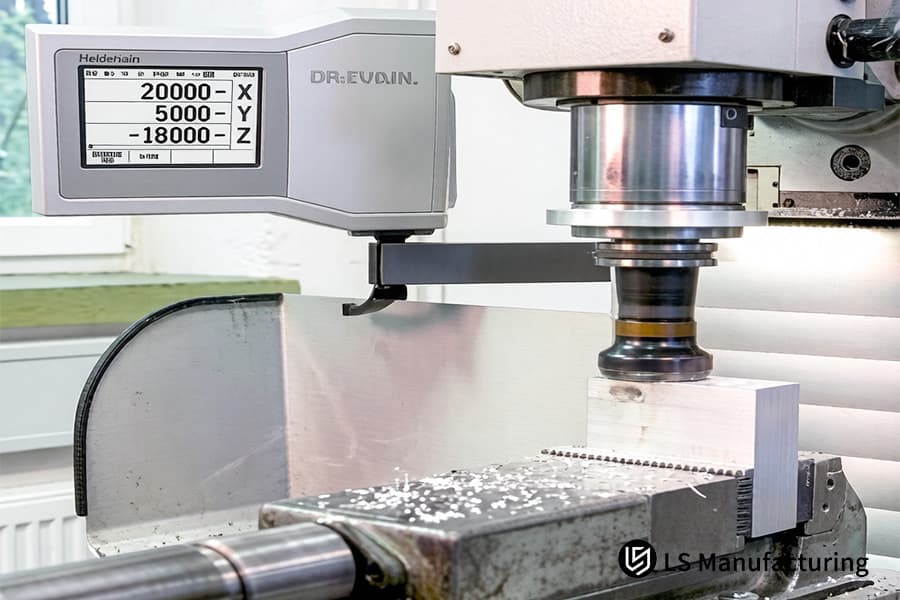
Figure 4: Machining a 6061 aluminum heat sink base with 0.01mm tolerance for electronic device thermal management.
How Does Lathe Machining With DRO Manage Thin Walled Part Deformation During High Speed Cutting?
Classical approaches in lathe machining fail to guarantee the achievement of stability in dimensions when working with thin-walled aluminum cylinders with wall thickness less than 0.5mm. In our lathe machining with DRO, hydrostatic mandrels along with control of radial displacement are applied for compensation of elastic deformations before deformation hardening. It makes sure that the roundness tolerance is maintained at 0.01mm at the speed of spindle above 3000 rpm:
Hydrostatic Mandrel Pressure Modulated by DRO Feedback
In our suggested technique, mandrels that are expandable using hydraulic pressure are used; the degree of pressure required depends upon the amount of radial runout that has been determined by the DRO prior to performing additional roughing operations. In case of runouts greater than 0.004mm, there is a gradual reduction in the use of hydraulic pressure so as to avoid vibrations. This application forms the core concept of thin-wall CNC turning.
Sequential Stress Relief Passes Guided by Displacement Trends
Before final profiling, two progressive roughing processes remove bulk material while the DRO records variation in stock thickness through each quadrant. Should deflection data indicate the potential for springback, intermediate resting periods relieve any stress built up prior to moving on to the next stage of machining to avoid the compounding effect, ensuring cylindrical accuracy within 0.012mm during precision lathe machining services of tubular aircraft structures.
Dynamic Speed-Feed Optimization Against Vibration Thresholds
Real-time monitoring of harmonic frequency by the DRO decreases either feed or spindle speed if vibration occurs that threatens the surface quality of thin walls (Ra<0.8 μm) due to the presence of vibration during thin wall machining. Critical features retain dimensional stability even at rapid metal removal rates for reliable high-stability CNC turning.
In contrast to traditional stores, where error detection happens after the post-production stage, our lathe machining with DRO feature live deformation control that ensures quality products from beginning to end. With our system, we prevent deflections by synchronizing the hydrostatic clamping process with displacement values, ensuring parts with aviation-standard roundness and guaranteed assembly accuracy.
LS Manufacturing: Custom CNC Machining Case Study—Precision 316L Stainless Steel Spindles For Medical Robots
Medical robots require perfect rotational consistency; any thermal drift occurring during machining will affect the safety of minimally invasive instruments. The following is an example of how LS Manufacturing was able to solve the problem of persistent spindle runout experienced by one of its customers, which is an established OEM, using its precision lathe machining services:
Client Challenge
The customer had an issue with their supplier because the supplier was facing problems related to progressive thermal drift while performing high-accuracy CNC turning processes of 316L surgical spindles. It caused coaxiality issues of 0.04mm along with harmonic imbalance and vibration at 10,000rpm, leading to scrap rates of 25%.
LS Manufacturing Solution
Manufacturing processes were updated for a 3-axis DRO-enhanced CNC turning services. Cryogenic treatment ensured 316L microstructure stabilization prior to machining, with DRO providing offset adjustments every 45 seconds to account for thermal elongation detected. Temperature-controlled coolant was applied throughout medical-grade CNC turning finishing operations, ensuring process stability within ±1°C.
Results and Value
Coaxiality of the final spindle reached 0.005mm, bringing yields up to 99.8%. The assembly sound levels of the client were reduced by 20dB, and savings from scrapped materials per year were more than $150K. Shorter and faster reliable CNC turning cycles helped reduce production time by 30% and expedite product release. Proven performance enabled LS Manufacturing to become their sole provider of precision machining for Class III medical devices worldwide.
Utilizing controlled thermal stabilization and looped DRO control, LS Manufacturing is able to turn potential hazards during medical machining into certainty through the application of deterministic manufacturing. Through our specialized precision lathe machining services, we are able to achieve clinically approved spindle stability at the same time as decreasing overall cost of ownership.
Is your spindle vibrating due to excessive runout? Contact our team of CNC turning experts immediately for a diagnosis.

FAQs
1. Why is LS Manufacturing the preferred supplier for precision CNC turning services for OEM projects?
Not only do we have the capability to deliver machining accuracy of ±0.01mm as our machining base, but we also offer process dashboards driven by DRO system, ensuring full traceability and interchangeability for each piece.
2. Can you achieve 0.01mm tolerance CNC turning on high-hardness, heat-treated materials?
Yes, by employing state-of-the-art PCBN tools in conjunction with micron-level adjustments through DRO, LS Manufacturing can ensure ±0.01mm tolerance machining of hardened parts with HRC 60 hardness.
3. How does DRO integration improve lead times for custom lathe machining services?
The use of DRO systems decreases the need for retooling and in-process measuring. Thanks to real-time coordinate monitoring, LS Manufacturing has managed to decrease the setting time of shafts machining processes by more than 40%.
4. What is the typical pricing for high-tolerance CNC turning at LS Manufacturing?
Pricing depends on the complexity of parts and batch sizes. With the assistance of DFM optimization, we usually manage to reduce the cost of machining by up to 15% for our customers without compromising on accuracy. You can get an instant quote by uploading your drawings directly to our system.
5. Why is CNC turning for precision parts essential for semiconductor equipment components?
Vacuum integrity is a critical requirement in the semiconductor industry. Thanks to our precision machining services, the micro-structure of the mating surfaces will not be affected; hence, an incredibly low outgassing rate will be maintained.
6. Can LS Manufacturing handle small-batch prototyping for complex lathe parts?
Certainly. There are no MOQ requirements, and LS Manufacturing provides specialized solutions for the fabrication of high-accuracy prototypes with small batches of up to 10 pieces. Delivery will take place within 5 days after the confirmation of the drawings.
7. Do you offer ISO-compliant inspection reports alongside your DRO-assisted lathe machining services?
For each batch order, we offer detailed documentation on quality assurance, such as CMM inspection reports, material certification, and self-inspection certificates through the DRO system.
8. How can I get a quote for precision lathe machining services within 24 hours?
Just send us your STEP or PDF files along with the purpose of use. The professional quotation team from LS Manufacturing will deliver you a proposal within 24 hours.
Summary
What matters about precision is not the expensive nature of the machinery used, but rather the level of care that has been taken regarding every single one of those 0.01mm changes in measurement throughout the machining chain. Thanks to our application of highly advanced DRO technology in our precision lathe machining service, LS Manufacturing is able to address any existing precision issues associated with conventional turning processes. Not only will you get premium quality parts from us, but also the guarantee of superior quality that can secure a definite advantage in the competition for you.
Does your company suffer from assembly problems due to poor machining precision on the part of your suppliers? Do not let yourself be held back in your research and development efforts by a low efficiency machining chain. Reach out to LS Manufacturing now to get your very own "Precision Turning Feasibility Assessment Report" (DFM recommendations included), created specially for you by our experienced engineers. Click here now to upload your drawings and get an instant quote for your project within 24 hours; LS Manufacturing can be your dependable partner in precision manufacturing.
Stop spindle vibration. Achieve 0.005mm concentricity with our DRO-integrated precision CNC turning.
📞Tel: +86 185 6675 9667
📧Email: info@lsrpf.com
🌐Website: https://lsrpf.com/
Disclaimer
The contents of this page are for informational purposes only. LS Manufacturing services There are no representations or warranties, express or implied, as to the accuracy, completeness or validity of the information. It should not be inferred that a third-party supplier or manufacturer will provide performance parameters, geometric tolerances, specific design characteristics, material quality and type or workmanship through the LS Manufacturing network. It's the buyer's responsibility. Require parts quotation Identify specific requirements for these sections.Please contact us for more information.
LS Manufacturing Team
LS Manufacturing is an industry-leading company. Focus on custom manufacturing solutions. We have over 20 years of experience with over 5,000 customers, and we focus on high precision CNC machining, Sheet metal manufacturing, 3D printing, Injection molding. Metal stamping,and other one-stop manufacturing services.
Our factory is equipped with over 100 state-of-the-art 5-axis machining centers, ISO 9001:2015 certified. We provide fast, efficient and high-quality manufacturing solutions to customers in more than 150 countries around the world. Whether it is small volume production or large-scale customization, we can meet your needs with the fastest delivery within 24 hours. choose LS Manufacturing. This means selection efficiency, quality and professionalism.
To learn more, visit our website:www.lsrpf.com.