Machining processesare the heart of manufacturing. Yet, selecting the right operation for your part can be challenging. Companies that do not adequately match materials to precision and cost requirements can experience production delays, inconsistent quality, and unexpected costs.All of these factors impact the overall success and profitability of a project.
At present, the selection method is mainly dependent on empirical judgment.As a result of lacking of a systematic selection procedure, it is easy to cause the equilibrium of performance and economy to be uncertain, which may lead to over design or underperformance. With a systematic knowledge system and 20 years of practical experience, this paper intends to provide a general selection framework to realize a more systematic selection.
Machining Processes Quick Reference Table
| Category | Process | Material Compatibility | Typical Tolerance (mm) | Surface Finish (μm) | Key Applications | Cost Level |
|
Turning |
Metals, Plastics |
±0.01 |
0.8-3.2 |
Shafts, Bushings, Flanges |
Medium |
|
|
Milling |
Metals, Plastics, Composites |
±0.01 |
0.8-3.2 |
Housings, Brackets, Molds |
Medium-High |
|
|
Drilling |
CNC Drilling |
Metals, Plastics |
±0.05 |
1.6-6.3 |
Holes, Tapping, Reaming |
Low |
|
Grinding |
Surface Grinding |
Hardened Metals, Ceramics |
±0.002 |
0.1-0.8 |
Precision Flat Surfaces |
High |
|
EDM |
Wire EDM |
Conductive Materials |
±0.005 |
0.4-1.6 |
Complex Shapes, Hard Materials |
Very High |
|
Laser Cutting |
Fiber Laser |
Metals, Plastics |
±0.1 |
1.6-12.5 |
Sheet Metal, Thin Plates |
Medium |
|
Waterjet |
Abrasive Waterjet |
All Materials |
±0.1 |
3.2-12.5 |
Thick Materials, No Heat |
Medium |
|
Additive |
3D Printing |
Polymers, Metals |
±0.1-0.3 |
6.3-25 |
Prototypes, Complex Parts |
Varies |
The above table allows the reader to easily compare various machining processes and pick the right one depending on theirmaterial, tolerance, surface roughness and cost requirements. It helps engineers decide the best option available while balancing the trade-offs between the available technology and economy.
Why Trust This Guide? Practical Experience From LS Manufacturing Experts
At Machining Processes, theory is not enough. Our experience comes fromover 10 yearsin the trenches of a shop, not a classroom.We have produced over 50,000 custom CNC machined parts,confronting the realities of difficult materials, tight tolerances and intricate design on a daily basis. Every part has been a learning experience, with practical application of principles learned from sources such asASTM International.
We routinely machine parts for the aerospace, medical implant, and performance automotive industries, where tolerance and material characteristics are a matter of life and death. Our knowledge and experience are tested in the field every day and conform to the requirements ofMIT Open Course Ware and other relevant texts.
This is why the suggestions in this guide are based on hard-earned experience, having learned from the mistakes we made in the beginning.We impart practical advice that has been proven with coolant, shavings, and inspection reports, not just theoretical lessons from a textbook. Rest assured that the information you find in this article is also what we use to achieve quality every day and effectively resolve everyday machining issues.
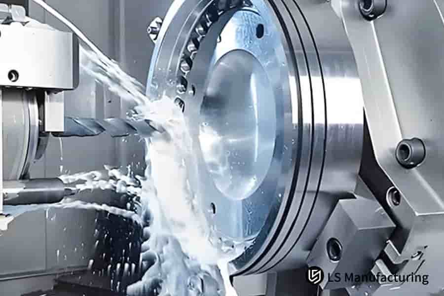
Figure 1: Refining manufacturing processes using advanced CNC technology by LS Manufacturing
What Core Knowledge Systems Should A Complete Machining Process Guide Include?
- Foundation: Materials and Mechanics:The foundation of aknowledge systemis a solid understanding of the material. The properties of metals, plastics and composites, how they react to machining, temperature and pressure and the most likely failure modes and risk mitigation should be the foundation of anyknowledge system. Then the next application will be able to predict how the material will react and generate optimal operating parameters to minimize the risk of failure.
- Equipment and Tooling Mastery:A proper list of available lathes, mills, and even5-axis CNC machiningcapability should be defined in the guide. Additionally, any available tool geometry, substrate, coating, and what the tool is used for should also be covered. This enables precise matching of resources to the task, a core goal of effectiveprocess selection.
- Optimized Parameters and Operations:Specifying feeds, speeds, depth of cut and coolant for each individual operation (milling, turning, etc.); themachining processes guideincludes recommended parameters based on material removal rates, tool life and surface finish. A completemachining processes guideincludes a knowledge base and application strategies.
A perfectmachining processes guidewould be a combination of an information resource and a practical experience. It would give engineers a framework for intelligentprocess selectionwhich would enable them to optimize production and obtain substantial improvements in productivity,quality and profitability.

What Are The Characteristics And Applicable Scenarios Of Different Types Of Machining Processes?
The manufacturing landscape offers diverse machining processes types, each with uniquecharacteristics that make them suitable for specificapplication scenarios. When deciding which type of machining service to use, you need to consider the material, geometry, tolerance and volume that you are looking for. Here we will introduce how to differentiate the machining processes.
| Process Type | Key Characteristics | Typical Application Scenarios |
|
Turning |
Accurate about axis of rotation, cylindrical, good finish |
Shafts, bushings, flanges and rotating parts |
|
Milling |
Versatile3D machining, complex geometries, multi-axis capabilities |
Housings, brackets, molds, and prismatic parts |
|
Drilling |
Rapid formation of holes, readily mounted, relatively cheap if drilled in holes |
Fastener holes, mounting points, clearance holes |
|
Grinding |
Ultra-high accuracy, fine surface finish. Has capability to grind hardened metals |
Making precise bearings, metal-cutting tools, and wear surfaces |
|
EDM |
No contact cutting, complex shapes,hard materials |
Intricate dies, molds, and heat-treated components |
|
Laser Cutting |
Non-contact processingwith relatively fast processing and small heat affected zone |
Rapid production ofsheet metal partsand thin sections |
|
Waterjet |
No thermal stress, cuts any materials, thick sections |
Composite materials, thick plate materials, and temperature-sensitive materials |
|
Additive |
Complex geometries, waste is low,freedom of design |
Prototypes, customized molds, high |
Benefits fortypes of machining processesare numerous, and usage of the machining process has to be taken into consideration for the particular task.Process selectionfor your project would depend on the knowledge of the benefits associated with the selected machining process and apt for your project. Knowledge of recognized usages would enable you to perform with utmost effectiveness for any project.
How To Select The Most Suitable Machining Process Based On Product Requirements?
How tochoose machining processasks for the evaluation of several factors, and the best possible result will only be achieved after the evaluation of these factors. The determination of the process needs technical and economical foundations.
- Material properties:The materials used also differ when it comes to how easily they can be cut using machining techniques. While some materials may be hard, for example, titanium requiring special cuttings tools referred to as EDM machines, there may be others that are soft, for example, aluminum that can be cut by a milling machine/turning machine.
- Dimensional accuracy and surface finish:The degree of precision will decide the machining type. The parts needing higher precision would include grinding or honing as finishing operations, while roughing operations would entail more harsh procedures. The required surface finish would determine the needs of the secondary finishing procedures.
- Production volume and cost considerations:The type of batch being produced incurs associated costs in the entire production process. Considering the production of large volumes, the most appropriate technology to adopt for the entire production process would be the use of automated machining, but for small volumes,the most appropriate technology for the entire production process would be the use of flexible machining techniques, which includesCNC machining.Theintelligent recommendationsystem designed by LS Manufacturing takes all these factors into account effectively.
- Geometric complexity and feature accessibility:The geometric complexity may involve holes that are deep, walls that are thin, and so forth. Such geometric complexities may require machining by two or more axes or even non-conventional machining.Feature accessibility may also affect machining tools to be used.
These days,machining process selectionis not just about the material property and process capability but also about cost. Only the consideration of the above 7 processselection criteriaand utilizing the advancedintelligent recommendationsystem could ensure the best outcome in terms of technology and economics. According to the industrial application results, the suitability of the process increased by25%and the cost was reduced by15-30%after using the machining process optimization system provided by LS Manufacturing.
What Are The Key Decision-Making Factors For Selecting Machining Processes?
The machining process selectioncannot be an easy decision. There has to be some consideration regarding the technical and economic aspects. The choice regarding machining is a key decision, and it has a bearing on both the time and the quality.
- Technical Feasibility Factors:Material properties, part geometry complexity, and required tolerances are the primarydecision factors. Hardness, machinability, thermal conductivity, and surface finish of the workpiece material dictate the process used. Part geometry can demand a multi-axis machine or require custom building of a machine.
- Economic Considerations: Cost analysisforms a critical component ofmachining process selection. This includes equipment investment, tooling costs, cycle time, labor requirements, and setup expenses.High-volume productionmay justify automated systems, while low-volume parts often favor flexible machining centers.
- Quality and Performance Requirements:Surface finish, dimensional accuracy, and mechanical properties are key decision factors.The process should be capable of delivering the required quality as well as should be efficient. The capability, repeatability and delivering the required mechanical properties should also be considered.
Amachining process selectionstrategy should combine the technical, economic and quality considerations through an integrated approach. Using thiscomprehensive evaluation, manufacturers can determine whichmachining processbest suits their needs and balances their constraints for performance, time, and cost and increase their overall market competitiveness.
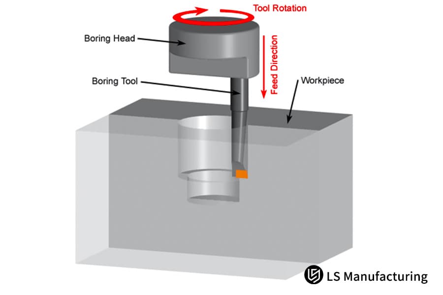
Figure 2: Analyzing CNC boring techniques for the best performance by LS Manufacturing
How To Compare And Choose Between Different Machining Processes In Terms Of Cost And Precision?
In mechanical manufacturing, themachining process comparisonplay an important role in the optimization of efficiency and machined qualities. Each process has its peculiar behavior with respect tocost-precision, so aneconomic analysisbecomes very important in choosing the best option.
| Process | Cost Level | Precision Range (μm) |
Typical Applications |
| Turning | Low | 10-50 | Shafts, cylinders |
| Milling | Medium | 5-20 | Complex surfaces |
| Grinding | High | 1-5 | High-precision parts |
| EDM |
Very High |
1-3 | Hard materials |
For effective selection in machining processes, it is required that there should be calculations pertaining to both technical and economical aspects.It has been concluded and observed bymachining process comparisonthat it is correct that highercost-precision. Optimum use of manufacturing processes can thus be made by manufacturers based on aneconomic analysis, and the most economical and apt machining process can be selected.
How To Maximize Machining Results Through Process Optimization?
Optimize machining resultsrequires a holistic approach towardsprocess improvementwithparameter optimization. By optimizing critical variables, industries can achieve maximum optimization outcome in efficiency as well as quality.
Parameter optimization through DOE
Design of Experiments (DOE)technique enables the evaluation of different parameters at once to identify optimal results concerning cutting speed, feed rate, and depth of cut. In fact, this technique is a scientific process of eliminating uncertainties while relying on facts to get optimal machining performance at low testing costs.
Process Enhancement with Constant Monitoring
Disparities in themanufacturing processescan be easily identified with the aid of a constant monitoring system, and this results in an automatic update to enable smooth processing to continue. Based on the knowledge of wear rate, surface finish, and accuracy of the monitoring system, a manufacturer can produce items with no defect.
Availability of better tools and materials
Depending upon the requirement, it becomes necessary to choose appropriate cutting tools and work piece materials in order to have a significant effect on the machining operation.When the cutting tool and the material of the work piece are properly identified based on their compatibility, it becomes possible to improve the life and speed of the cutting tools and thereby reduce the cost.
For an effectiveprocess improvementto be realized, it will be necessary to take an holistic approach that incorporates scientific processes forparameter optimization. This will ensure that the manufacturer takes the necessaryoptimize machining results.
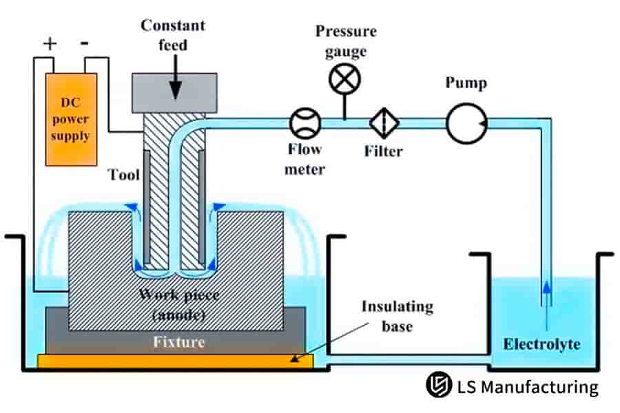
Figure 3: Configuring electrochemical systems for CNC precision operations by LS Manufacturing
What Are Some Innovative Applications Of CNC Machining Technology In Modern Manufacturing?
TheCNC machining processeshave brought in a revolution in the sector of manufacturing, resulting in accuracy in the process using digital control systems. Present technological advancements are capable of delivering complex forms with high accuracy, unimaginable in the context of the conventional machining process. The integration ofinnovative applications indigital manufacturing has transformed how industries approach production, from aerospace components to medical devices.
Turn-Mill Machining Centers
This equipment can perform theturning and milling processin one machine. It is aninnovative applicationbecause this technique gives less part handling and setup time. This equipment can perform machining on a part of high complexity without changing the machine from raw to finished. This technique can be said to be accurate because, throughout this process, the part is maintained in a fixed position.
High-Speed Machining
By applying the use of spindle technology as well as cutting tools, thisCNC machining processhas the capability of effectively removing material. The machining process is most ideal for mold & die machining as well as aerospace aluminum machining due to the speed and accuracy that the process offers. The machining process is an extremely beneficial process owing to its advantages.
Digital Twin Technology
The notion or concept presented herein is that thedigital manufacturingwould ensure the simulations of the machining process would be possible prior to the commencement of the manufacture process itself. All the above would ensure the costs associated with the setup process were kept to a minimumwhile there would be no material loss at all with the errors being kept to a minimumthat would have occurred while the product was being manufactured.
Additive and Subtractive Hybrid Manufacturing
It is possible to create an object by performing3D printing and CNC machining processes, creating an object by additive manufacturing with an added feature of near-net shape properties, and finally modifying it by performingCNC machining operations. Theinnovative applicationproves to be very useful and appropriate for creating parts with internal details, which are difficult to produce through machining. It becomes feasible to leverage the best that both worlds have to offer, i.e., complexity and precision.
In fact, it should also be mentioned here that the above-mentioned points are only a few among a myriad of ways where technical improvements regarding theCNC machining processeshave been steadily occurring, relative todigital manufacturing, and thus, manufacturers have been able to achieve unheard of levels of precision, speed, and complexity. In this regard, apart from the aforementioned point, it would not be wrong to say that the development ofCNC machiningwould play a pivotal role within the development of digital manufacturing, amongst others.
How Can High-Precision Machining Processes Meet Stringent Quality Requirements?
Precision machining processesare an extremely important area to consider from the standpoint of thequality requirementsthat the manufacturing industry has. Precision machining is the process applied in creating high-quality parts, which possess outstanding attributes such as precision.
- Advanced Equipment and Technology: Modern precision machining relies on state-of-the-art CNC machines, multi-axis machining centers, and EDM (Electrical Discharge Machining) systems.These technologies work in controlled environments with temperature and humidity regulation to maintain micron-level accuracy throughout the production process, ensuring consistent quality across batches.
- Comprehensive Quality Control System:Excellent precision machining needs ahigh-quality control systemas its backbone. That would mean inspection of the work in various stages of processing by coordinate measuring machines, optical comparators, and surface roughness testers. SPC system allows for keeping the parameters of production under control at all times with instant adjustment in keeping thequality requirements.
- Material Selection and Process Optimization:Selection of the right material and the method of its machining often play a vital role in the final product outcome.Machining tools, speeds, feeds, and coolant usageduring machining are often optimized to prevent thermal deformation.
- Applications in Critical Industries:Some of the applications that fall underprecision CNC machining processesinclude aerospace engineering applications, applications within the field of medical instruments, automobile applications, and applications within the electronic industry. For the aforementioned applications, which include blades used in turbines, medical instruments, and semiconductors, the applications become highly stringent in nature.
- Continuous Improvement and Certification:Major companies follow procedures related to continuous improvement, apart from being certified inISO 9001 and AS9100.Precision machining processesmeets the requirements or exceeds them so far as specifications are concerned with procedures concerning equipment calibration, operator training, and process validation.
Precision machining processesrefers to high-precision manufacturing technology which implements various manufacturing processes with high-precision control, positioning, and motion control. By strictly controlling thequality requirementsin the manufacturing process,micron-level accuracycan be guaranteed and is used in parts manufacturing for high-tech industries such as aerospace, semiconductor, and automobile.
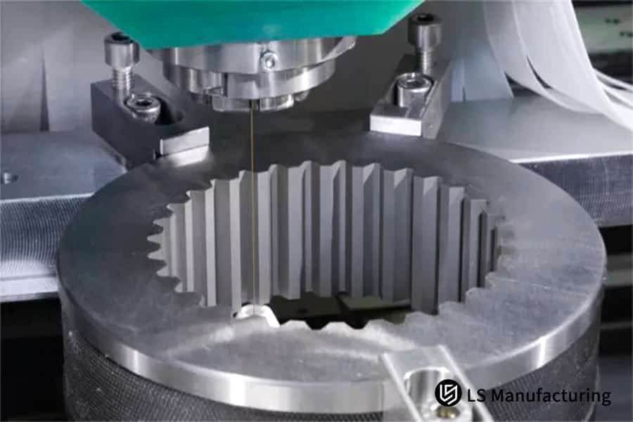
Figure 4: Choosing the most effective high-precision CNC method by LS Manufacturing
LS Manufacturing Aerospace: Multi-Process Machining Solution For Engine Turbine Blades
In the aerospace field where all three of precision, strength, and light weight are required at the same time,LS Manufacturingprovided amulti-process machiningsolutionto a customer manufacturing blades for aero-engine that solved a big manufacturing issue.
Client Challenge
A leading aerospace manufacturer was struggling to produce high temperature alloy turbine blades to customer requirements. The existing solution was a single process solution that could not deliver both complex profile accuracy and excellentsurface finish. As a result, the product qualification rate was only 85% due to the above problems, which caused high production costs and long lead time.
LS Manufacturing Solution
We proposed a complete solution to the customer to turn the blades for roughing,5-axis millingfor precise profiling and polish for finishing.With our proposal, the customer is able to control the optimal parameters for each process and therefore can achieve the best profile accuracy, surface roughness and processing time.
Results and Value
Following our use of integrated machining, the qualification rate of parts was increased to99.2%and the overall processing time was shortened by30%. Our outstanding performance not only helped our customer reduce annual processing costs by over2 million RMBbut also led to the formation of a strategic partnership between us.
That a supplier like LS Manufacturing could find an application for a state-of-the-art multi-process CNC machine toolto produce a hard-to-make aerospace component when an existingless-than-ideal legacy machinethat would have worked was already on the floor says a lot about their ability to support innovations that lead to improved quality, productivity and cost savings.
Bring your aerospace components to the next level with our machining processes solutions.

How To Pstablish A Scientific Mechanical Processing Technology Management System?
A scientific management system for a mechanical processing technology should be established in which theprocess managementis integrated with the characteristics of precise machining in order to guarantee the quality of products and the efficiency of processing.
Standardized System Framework
A goodstandardized systemframework is a must for a smooth process management. It includes process documentation, work instructions, and standardized operating procedures. The system must be comprehensive covering all steps of the part from raw material to final inspection and should have well-defined quality parameters.
Precision Machining Processes
It is important that a sophisticatedprecision machining processesis adopted if precision on a micron scale is to be achieved. It consists of appropriate machine selection, appropriate cutting parameters, and appropriate environmental conditions. These processes should be designed to deliver thequality requirementsbut with minimum variations and defects.
Continuous Improvement Mechanism
A system forcontinuous improvementmust be present in effective process management. This entails analysis and solving problems within the process. It should enable an organization to attainmicron-level accuracyand reduce costs incurred in production.
Quality Control Integration
There are quality control procedures that will ensure thequality requirementsare being met. These can be done through statistical process control, calibration, and acceptance criteria. There has to be a monitoring system in theprecision machining processesthat will be able to identify any variation from the standard process.
Performance Measurement and Optimization
By developing key performance indicators forprocess managementkey performance indicators for management, there can be an objective evaluation regarding system efficiency. The factors to be established in key performance indicators for management are cycle time, first-pass yield, equipment use, and cost per part.
A scientific mechanicalmachining process management systemcombinesstandardized systemframeworks with advancedprecision machining processesto achieve consistentmicron-level accuracy. By embeddingcontinuous improvementprinciples and rigorousquality requirementsthroughout the organization, manufacturers can enhance operational efficiency, reduce variability, and maintain competitive advantage in the market.
FAQs
1. In what ways does suitable material differ from others?
In our proposed system, we shall recommend the most suitable process based on the material. If the material is an aluminum material, we shall recommend the high speedmilling process. If the material is the stainless steel material, we shall recommend the mill turn process.
2. What is the economical and efficient process when the quantity is small?
We shall offer flexible process. Through sharing resources, we can reduce the expense for smaller quantity by20-30%.
3. In what ways is it possible to verify the technical feasibility and economy of the novel process?
Accordingly, we shall conduct a process test and cost analysis to that effect. We shall validate through samples that our process solution is indeed effective and cost-effective. If you need a detailed cost evaluation for your project, you can get aninstant online quoteright now to verify the economy of your design.
4. Do you have particular process combinations for difficult-to-manufacture parts?
There will be design work on various process combination programs based on the structural attributes of the parts, as well as the process simulation to ensure that the parts designed are of high quality.
5. How to prevent quality risks related to changes in processes?
We follow a very strict change control process. After the verification test, we can ensure that the changed process is in control as far as the quality is concerned.
6. Can you provide machining process training and optimization assistance?
It should be noted that we have a complete training system for processes and process optimization and can assist the company in improving process technology.
7. How should the balance be affected in machining precision and expenses?
The optimal point between the two, in terms of cost-effectiveness for both overprocessing and underaccuracy, is reached by applying the value engineering analysis process.
8. What are the key considerations for process changes?
Provideend-to-end servicesfor process changes, including equipment selection and training of personnel, among others. This would ensure seamless implementation of the process changes.
Summary
High production and quality production can be achieved through scientific selection and management of processes.Having the experience and technical knowledge of the industry and supplier knowledge, LS Manufacturing provides their customers with process solutions that can be used to enhance their own manufacturing processes and grow their business.
Get in touch with the process experts at LS Manufacturing today to experience how our free process solution evaluation can work for you. At LS Manufacturing, what we promise is that we can provide you withprofessional CNC machining solutionassistance that will ensure you have a successful process.
Get a free process solution assessment now to optimize your production process and enjoy up to 30% cost savings and 25% process compatibility improvement!
📞Tel: +86 185 6675 9667
📧Email: info@lsrpf.com
🌐Website:https://lsrpf.com/
Disclaimer
The contents of this page are for informational purposes only.LS Manufacturing servicesThere are no representations or warranties, express or implied, as to the accuracy, completeness or validity of the information. It should not be inferred that a third-party supplier or manufacturer will provide performance parameters, geometric tolerances, specific design characteristics, material quality and type or workmanship through the LS Manufacturing network. It's the buyer's responsibility.Require partsquotation Identify specific requirements for these sections.Please contact us for more information.
LS Manufacturing Team
LS Manufacturing is an industry-leading company. Focus on custom manufacturing solutions. We have over 20 years of experience with over 5,000 customers, and we focus on high precision CNC machining,Sheet metal manufacturing,3D printing,Injection molding.Metal stamping,and other one-stop manufacturing services.
Our factory is equipped with over 100 state-of-the-art 5-axis machining centers, ISO 9001:2015 certified. We provide fast, efficient and high-quality manufacturing solutions to customers in more than 150 countries around the world. Whether it is small volume production or large-scale customization, we can meet your needs with the fastest delivery within 24 hours. choose LS Manufacturing. This means selection efficiency, quality and professionalism.
To learn more, visit our website:www.lsrpf.com.