CNC milling services, traditionally used to machine transmission valve body parts, do not address the critical problem of "silent valve," where parts meet size requirements but cause failures such as shift shock due to micro-burrs, leakage due to thermal deformation, and contamination-induced stiction, all of which stem from a "discrete hole machining" philosophy that ignores hydraulic performance.
This is done by advancing CNC milling from feature creation to "hydraulic performance injection," where CFD Simulation, process compensation of thermal distortion, and "synergistic finishing" such as "super boring+honing+plasma polishing" reduce critical bore roughness from Ra 0.4μm to Ra 0.1μm, achieving a 60% reduction in Cv value fluctuation while providing guaranteed hydraulic performance to ensure seamless, reliable, and robust transmission operation.
CNC Milling For Hydraulic Valve Bodies: Critical Guide
| Technical Challenge | Precision Manufacturing Solution |
| Complex Internal Passage Networks | Machining complex and intersecting oil passage networks with precise diametric and surface characteristics and passage intersections for precise fluid dynamic control and prevention of cavitation. |
| Critical Spool Bore Geometry | Achieving ultra-precise diameter, roundness, straightness, and surface finish for smooth and unobstructed spool movement and precise metering action. |
| Dimensional Stability Under Pressure | Ensuring the housing does not distort under high fluid pressure and temperature exposure; this is ensured by the use of stabilized materials and stress-relieving machining processes. |
| Multi-Material Integration | Achieving precise interfaces for sealing surfaces, sensor ports, and solenoid mounts by taking into account the varying characteristics of the materials in a single setup. |
| Our Process-Centric Methodology |
Utilizes high-pressure through-spindle coolant and specialized boring tools with in-process probing for consistency in deep and small-diameter passage machining. |
| Surface Integrity & Deburring | Utilizes machining processes that avoid burr formation and specialized deburring processes for an absolutely clean and particulate-free fluid passage system. |
| Result: Precise Hydraulic Control | Provides the precise and accurate fluid flow control required for the best possible transmission shift quality, efficiency, and responsiveness. |
| Result: Long-Term Reliability | Ensures leak-free operation and long-term vehicle performance through perfect bore geometry and intersection of perfect passing surfaces. |
We solve the CNC milling challenge transmission valve bodies that require micron-level precision to achieve perfect performance. Our expertise in machining intricate internal hydraulic systems ensures leak-free, precise control of fluids. This has a direct impact on smoother gear shifting, fuel efficiency, and long-term reliability in automotive transmissions. Our data-driven approach ensures that every part meets the high standards required to function optimally.
Why Trust This Guide? Practical Experience From LS Manufacturing Experts
CNC milling services are a common topic, but we're a company of practitioners, not theorists. Our 15+ years of experience at LS has been spent fixing hydraulic valve body failure modes, ruining perfect shifts due to undetected burs, leakage due to thermal drift, and warranty claims due to contaminants. Every strategy we provide, whether it’s tool path optimization, burr formation, or other factors, has been tested in the crucible of manufacturing deadlines and zero-defect requirements to guarantee that the knowledge we provide is battle-tested for reliability.
Our approach is designed with industry standards in mind as a valve body is essentially a performance-critical fluid circuit. Our material selection process, heat treatment, and precise machining have been rigorously aligned with the specifications outlined in the Aluminium Association (AAC) guidelines as well as the performance testing criteria set forth by SAE International. This fundamental approach ensures that individual components are transformed into a cohesive system that is reliable and consistent in performance, even in the most adverse conditions.
The end result is quantifiable performance that you can specify with confidence. Our integrated finishing process ensures that our customers reap the benefits of a surface finish rating of Ra 0.1µm and bore geometry control in microns, resulting in a 60% reduction in flow variation. We are able to eliminate the root causes of failure and deliver the hydraulic integrity required for next-generation transmissions.
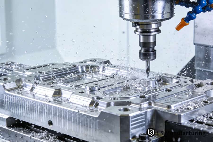
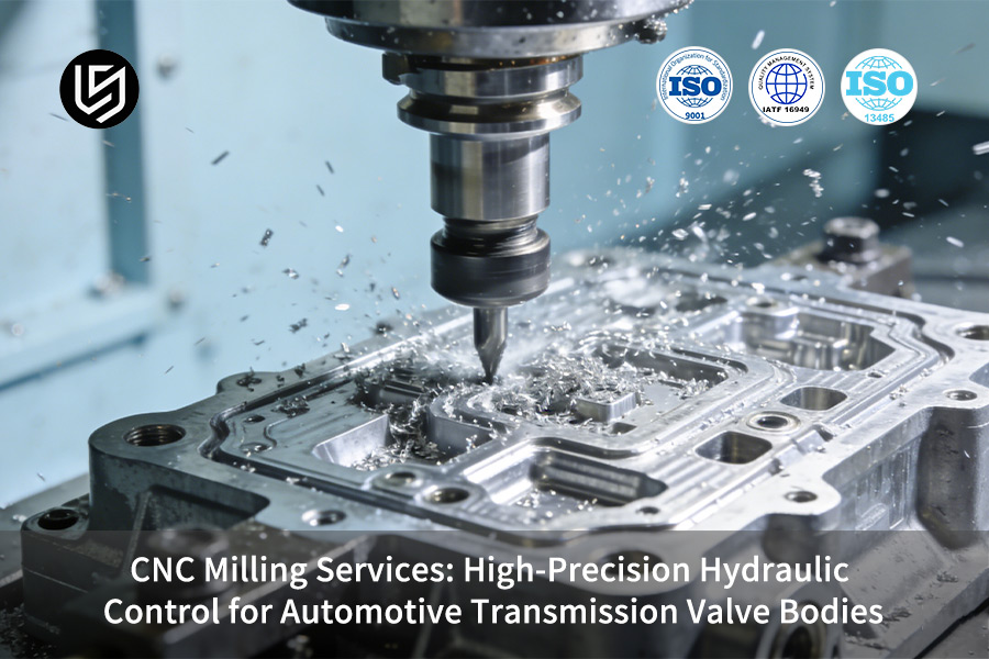
Figure 1: Operating high-precision CNC milling on metal alloy transmission valve bodies for automotive hydraulic systems.
What Are The Key Manufacturing Causes Of Hydraulic Valve Body Internal Leakage And Flow Inaccuracy?
Persistent internal leakage and erratic pressure control in hydraulic valve bodies are often traceable to specific, subtle manufacturing induced defects. This document details our systematic methodology for eliminating these failures at their source, moving beyond simple deburring to address the fundamental physical root causes. Our CNC milling solution encompasses:
Proactive Burr Prevention at the Machining Source
Removing burrs is not enough; we prevent them from occurring in the first place. This is accomplished through optimal CNC milling toolpath planning and engagement strategy for cross-holes and groove edges. We utilize specific CNC milling exit strategies and maintain our tools in pristine micro-geometry condition to prevent material tearing. This source-control approach ensures no sub-50µm hard particles are generated to cause secondary abrasion or alter flow characteristics, directly tackling the valve body leakage root cause.
An Integrated Process for Stress and Distortion Management
If left unrelieved, this residual stress ensures future micro-deformation. Our protocol involves thermal cycling of rough machined castings to stabilize them prior to final high-precision hydraulic control machining. Critical bore finishing is conducted in a single setup on temperature-controlled equipment. A final stress relief cycle is applied to components after machining. This entire process controls positional drift of bore families to <5µm throughout the operating temperature range.
Controlled Surface Texture for Optimized Function
While a desired Ra is a requirement, it is not the end objective. For spool bores, we control the direction of the surface finish. A customized honing method is utilized to provide a uniform axial texture parallel to spool motion. This controlled CNC milling methodology minimizes breakout friction, generating a stable leakage path, which has a direct impact on accuracy and hysteresis performance.
The following document represents a vastly different philosophy in the field of engineering. Our competitive advantage is our unique approach to engineering the process itself to be failure-resistant. We do not simply machine parts. We engineer and execute a certified process for material stabilization, precise machining, and functional surface generation that makes critical manufacturing induced defects statistically impossible.

How To Ensure Valve Bore Position And Cylindricity Via Multi-Axis Simultaneous Precision Milling And Boring Processes?
To ensure the positional accuracy and cylindricity of valve bores as precise guide surfaces for our spools, it is necessary to break away from traditional machining methods. Traditional multi-setup machining methods have inherent errors that compound with each setup. Our solution is an engineered multi-axis process that eliminates these errors at their source.
Eliminating Datum Stack-Ups with Single-Setup Machining
- Core Strategy: Machining of all critical features of all six faces is completed in one fixture using a 5-axis CNC milling center.
- How We Do It: We use rigid, dedicated fixtures, and optimized CNC milling for valve bodies toolpaths specifically designed for valve body parts. This prevents any possibility of re-clamping and re-establishing datums.
- Result Achieved: Positional tolerances between families of bores are maintained within ±0.008 mm, ensuring perfect spool alignment.
Hybrid Milling and Precision Boring for Ideal Bore Geometry
- Core Strategy: Use of a "bore first, mill second" approach using the best process available for each feature.
- How We Do It: Critical spool bores, such as IT6, roundness < 0.004 mm, are precision bored using multi-axis precision boring with on-machine probing for in-cycle compensation. Non-critical ports are machined using standard CNC milling operations.
- Result Achieved: Optimum bore cylindricity and surface finishes, giving us exactly what is needed to ensure minimal friction and leakage.
Proactive Compensation for Inevitable Thermal Effects
- Core Strategy: We predict and counteract any residual stress-induced distortion before it even happens in the final part.
- How We Do It: The components go through stress relief after the semi-finishing process. We then apply intentional offsets in the final CNC milling paths based on the FEA predictions of the distortion vectors.
- Result Achieved: A thermal distortion compensation mechanism, where the bores will be in true position and shape even after the machining and in service.
This is not just a series of actions and CNC milling steps. This is a system-level engineering approach. What sets us apart from the rest is the fact that it is a certified process. We offer a guarantee of the geometry of the bores through an inherently accurate process, providing the world with precision valves.
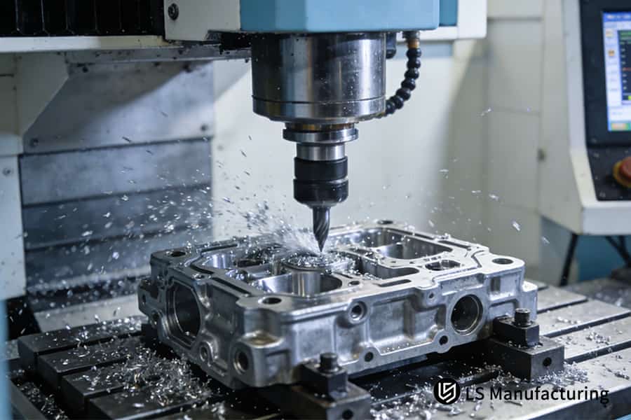
Figure 2: Active CNC milling a high-tolerance aluminum alloy hydraulic valve body for precision automotive transmission systems.
What Is The Ultimate Process For Cross-Hole Deburring And Flow Channel Surface Finishing?
The greatest challenge in hydraulic valve body manufacturing lies in the elimination of burrs in the internal cross-holes. This has the potential for catastrophic failure. Our solution lies in the application of a multi-step methodology that has been proven effective in raising the cleanliness levels of the manufactured part by several ISO code levels. This report presents the definitive technical methodology for the elimination of burrs in the manufacture of a hydraulic valve body:
CAM-Based Prevention in CNC Milling
The first stage in the prevention of burr formation lies in the application of CAM-based prevention in the CNC milling parts. In this stage, we optimize the tool paths for the part by avoiding full-width cutting at intersections. This first CNC milling strategy of the part involves altering the engagement angle and exit conditions, thus minimizing the burr volume.
Abrasive Flow Machining for Precision Edges
For final edge conditioning and micro-deburring, we employ abrasive flow machining. A viscous, abrasive-laden media is forced through the complex internal channels. This process uniformly radiuses edges and polishes surfaces to a fine finish, crucial for sensitive pilot circuits and metering edges, ensuring consistent fluid dynamics and preventing particle generation.
Validated Multi-Stage Post-Processing
According to the optimized CNC milling process, the parts are subjected to a sequenced series of post-processing steps. Ultra-high-pressure water jets exceeding 1000 bar clean the cross-holes to eliminate most of the existing burrs. As an additional step for stainless steel parts, a plasma electrolytic polishing step may be included to not only smooth the surface at a microscopic level but also deposit a corrosion-resistant passivation layer for maximum long-term cleanliness and reliability.
The documentation here represents a definitive approach to solving the problem of cross-hole deburring in a results-oriented manner, progressing from theoretical capability to practical procedure. This series of steps, from preventive machining through validated finishing steps, represents a high level of technical integration to resolve the industry's most intractable contamination problems for reliable components beyond specified cleanliness levels.
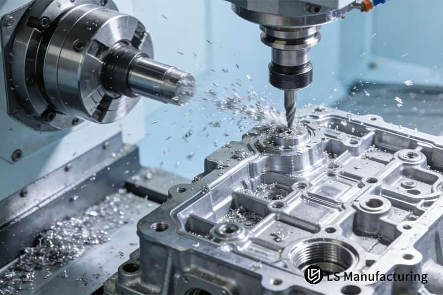
Figure 3: Fabricating intricate internal channels in alloy valve bodies for automotive hydraulic systems.
How To Achieve Dimensional Stability And Cleanliness Control In The Mass Production Of Valve Bodies?
Dimensional stability and supreme cleanliness are of paramount importance for the reliability of the output of the hydraulic system in the context of CNC milling batch production. This document outlines a data-driven methodology for controlling variability in the manufacturing process. This document establishes an actionable framework for ensuring consistency in the output of the system in the context of high reliability transmission valve body machining and custom valve body manufacturing processes.
| Control Pillar | Method & Measurable Outcome |
| Statistical Process Control (SPC) | Implement 100% in-process gauging for critical features with Cpk >1.67 through real-time batch consistency SPC charts. |
| Cleanroom Assembly Protocol | Execute multi-stage ultrasonic cleaning and vacuum drying in a Class 10,000 cleanroom environment with particulate levels meeting stringent cleanliness control targets for post-machining. |
| Integrated Traceability & Tool Management | Implement fixed tool life counts and full material lot traceability back to specific CNC milling operations for transmission valve parameters and billet material source. |
The structured approach tackles the basic issues in manufacturing by providing an integrated system for prevention, control, and traceability. This document explains the methodology for the elimination of the major causes of variation in advanced CNC milling processes. The methodology guarantees that all products, whether they are prototypes or production quantities, meet the stringent performance and reliability requirements for leak-free performance and durability in a definitive guide to competitive manufacture.
LS Manufacturing — New Energy Vehicle Sector: Hybrid Transmission Electro-hydraulic Control Module Valve Body Project
This document outlines how LS Manufacturing addressed a critical high-temperature leakage failure in a compact valve body of a hybrid Dedicated Hybrid Transmission (DHT). The LS Manufacturing new energy vehicle case is a good example of how we apply a scientific approach to solve the root cause of failures in electro-hydraulic products, ensuring built-in reliability in the products we manufacture.
Client Challenge
The complex aluminum DHT valve body of the client had extreme precision requirements for the integrated solenoid ports. The initial product had failed the thermal cycling test at 140°C, resulting clutch in leaks at the intersection of the cross-holes. The leaks had caused instability in pressure. This had a direct impact on the halt of the transmission validation process.
LS Manufacturing Solution
We redesigned a critical sharp corner to a smooth radius. The execution involved high-precision CNC milling, a dedicated drill-bore-hone-abrasive flow sequence, and mandatory post-machining stress relief. Finally, 100% functional testing validated the zero-leakage machining outcome for every unit, ensuring built-in integrity before shipment.
Results and Value
The designed valve bodies have completed more than 2,000 hours of testing with zero leakage. We have reached a stable CpK > 1.8 and exceeded cleanliness requirements in production. This has de-risked our client’s program, allowing them to clear all validation milestones for their DHT assembly and establishing a strategic supply relationship.
This case study demonstrates our company’s core competency in delivering verified reliability by controlling the entire process from complex CNC milling operations to final validation. We engineer our processes to remove potential issues in the end product, providing zero-leakage machining solutions that speed development in new energy vehicle programs.
Eliminate the risk of internal leakage in valve bodies under high-temperature and high-pressure conditions using our high-precision CNC milling and composite processes.

How Do You Validate The Dynamic Hydraulic Performance Of A Valve body, Rather Than Merely Its Static Dimensions?
While static dimensional accuracy is a fundamental but insufficient requirement for the functional reliability of precision automotive components, the following document describes a tiered approach for a hydraulic function testing protocol, intended to provide a level of validation for performance under simulated real-world operating conditions, as opposed to a simple pass/fail certificate of conformance.
| Validation Tier | Method & Quantifiable Outcome |
| 100% Leak & Flow Integrity Test | Every CNC milling part is tested for pneumatic leak integrity and flow resistance, ensuring there are no micro-leaks and flow coefficients fall within specified ranges. |
| Dynamic Pressure Response Validation | Random samples of the components are assembled with standard spools/solenoids and tested on a series of hydraulic rigs, measuring critical parameters such as pressure rise times (<10ms) and control accuracy under steady-state operating conditions (±0.5 bar). |
| Authoritative Cleanliness Certification | Random samples of the components are sent for ISO 4406 or NAS 1638 certification by independent third-party labs, providing a level of objective valve body performance validation. |
This protocol specifically bridges this gap between static conformance and system reliability. This protocol describes how to validate that a process, such as an automotive transmission valve body CNC milling process, is actually providing parts that operate dynamically as required. Providing certified performance curves and contamination data, this protocol is intended to provide the critical information required to ensure high-risk system integration, eliminating system failure, while providing technical sign-off for high-precision CNC milling operations.
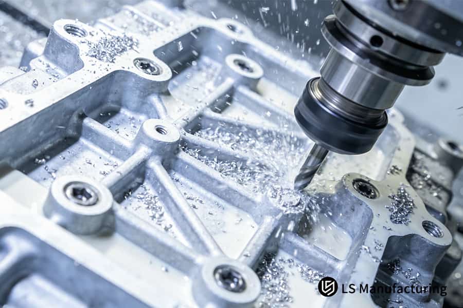
Figure 4: Milling high-precision alloy steel valve bodies for custom automotive high-precision hydraulic control machining systems.
What New Challenges Do Valve Body Manufacturing Face With New Materials And Electro-Hydraulic Integration?
With these emerging trends towards new materials, electro-hydraulic integration, and digital engineering, there is a redefinition of performance requirements for hydraulic manifolds. To effectively deliver CNC machined hydraulic valve bodies for these emerging applications, there is a need to overcome new challenges:
Advanced Machining of Lightweight Alloys
- Machining for new materials: Leverage special tool coatings, such as AlCrN, and high-pressure coolant approaches to effectively manage the galling and thermal distortion of high-strength die-cast aluminum or magnesium alloys.
- Process Parameter Optimization: Leverage trial run data from CNC milling trial runs to optimize stable parameters for machining, ensuring dimensional stability and surface finish for lightweight components.
Precision Integration of Electronic Features
- Unified Design for Manufacturing (DFM): Jointly collaborate on designs that enable the integration of PCB cavities, sensor ports, and harness channels into the custom valve body solutions.
- Multi-Process Synchronization: Coordinate the high-tolerance CNC milling of electronic features with downstream assembly operations, ensuring positional accuracy for sensor placement and connector alignment.
Simulation-Driven Manufacturing Workflow
- Predictive Cutting Simulation: Use finite element analysis software to simulate and pre-compensate for the distortion of the workpiece during complex CNC milling of transmission valve bodies, ensuring first-part correctness.
- Performance Validation via CFD: Use computational fluid dynamics analysis to simulate the optimized internal channel designs before actual machining begins.
This methodology establishes a specific framework for the transition from traditional machining to electro-hydraulic integrated machining. It addresses the fundamental problems in material instability, multi-process integration, and performance prediction. This specific approach to simulation-driven manufacturing, from digital twin to final part qualification, defines a specific standard for the development of future high-performance custom valve body solutions.
Why Is LS Manufacturing The Essential Choice In Areas Critical To Overall Vehicle Driving Quality?
The selection of the appropriate partner for the critical precision automotive CNC milling is the determining factor for the integrity and quality of the vehicle's hydraulics. This document will address why choose LS Manufacturing as your co-engineering partner in the industry, not just for the supply of the part but for the performance-based guarantee. This is accomplished by systematically connecting vehicle NVH and shift feel targets directly with validated manufacturing processes:
Demand-Driven Specification Definition
We start with analyzing issues in terminal performance, such as shift harshness or pressure ripple, and then reverse-engineer what specific manufacturing requirements need to be met to resolve these issues. This allows us to convert subjective targets for system refinement into quantifiable and statistically based targets for leakage rates, flow consistency, and cleanliness that surpass drawing tolerances, guaranteeing that each component meets system requirements.
Integrated, Performance-Led Manufacturing
Our process involves combining high-precision CNC milling services with subsequent finishing in a closed-loop system. This ensures that micro-level surface and edge finish from our machining process are preserved throughout subsequent cleaning and assembly operations, which solves the problem of maintaining system integrity in a hydraulic system to ensure quiet operation and consistent pressure control necessary for refinement.
Data-Backed Commitment to System Outcomes
We guarantee performance-based commitments with hard data provided by our real-time SPC data and 100% functional testing, providing a verifiable performance fingerprint for each and every batch. This allows us to guarantee the long-term performance of our certified automotive CNC milling services by directly connecting our demanding processes with the sustained vehicle driving characteristics and quality assurance.
The following document represents a performance-obsessed partnership and describes the process by which we transform vehicle requirements into a controlled manufacturing reality. By taking the role of a hydraulic integrity partner and integrating this with data-verified precision CNC milling capabilities, we are able to provide the validated platform required for the highest levels of vehicle NVH and driving refinement.
FAQs
1. How long does it take to machine a typical automatic transmission valve body?
From raw casting to the final product, encompassing all the processes such as machining, deburring, cleaning, and inspection, the lead time for the entire process takes around 5 to 7 business days. For processes requiring complex stress relief and coating operations, the lead time may extend up to 10 to 12 business days. You can request a instant CNC machining quote online to get precise lead times for your specific designs.
2. What level of precision can you typically guarantee for critical bores in aluminum valve bodies?
The precision levels that we guarantee for the bores include a tolerance of ±0.008 mm for the diameter of the bores (IT7 grade), a tolerance of ±0.015 mm for the positions, cylindricity of ≤0.005 mm, and a surface roughness of 0.4–0.8 μm. For the bores intended for steel sleeve valves, the precision levels are even higher.
3. How do you ensure the internal cleanliness of the valve bodies, and do you hold any relevant certifications?
We have an ultra-clean washing facility for the processes. The processes are fully compliant with the IATF 16949 standard. For each batch of the products, cleanliness inspection reports according to the ISO 4406 standard are also provided.
4. Will you alert me if my valve body design presents potential manufacturing difficulties or performance risks?
Yes, absolutely. We provide a complimentary, in-depth Design for Manufacturability analysis. Within 48 hours of receipt of your technical drawings, we can provide an in-depth DFM/A report, including recommendations on modifications, to address potential issues such as cross-hole burring risks, thin wall deformation, seal groove design, etc.
5. Can you provide sub-module assemblies that include everything from valve body machining to valve spool selection and testing?
Yes, we can. We can function as a modular supplier to provide fully assembled, tested sub-assemblies, including valve bodies, valve spools, and seals, which can function as a plug-and-play solution to simplify your supply chain and manufacturing process.
6. What is the Minimum Order Quantity (MOQ)? How does pricing vary with order volume?
We can handle prototyping and small-batch pilot runs, with MOQ as low as 10 to 50 units. Pricing varies according to volume in a tiered structure, eventually flattening out as a stable, cost-effective volume is reached to support mass production.
7. Do you support the use of specialized materials or surface coatings, such as anodizing or DLC (Diamond-Like Carbon) coatings?
The answer is yes; we fully support such requirements. We have extensive experience in machining different types of valve bodies made of aluminum alloys, ductile iron, and stainless steel materials. Moreover, we make use of the best external resources for the execution of special surface treatments such as hard anodizing, electroless nickel-phosphorus plating, and DLC coating for the fulfillment of special requirements for corrosion and wear resistance.
8. How do I initiate a collaborative assessment for a new valve body project?
Please provide your 3D models, your 2D technical drawings, your materials specifications, and your performance requirements. Our engineering team for hydraulic components will start the analysis within three business days and schedule a consultation with you. Then, we will provide you with a "project technical briefing" that explains our proposed manufacturing strategy and our budget estimate.
Summary
Hydraulic valve bodies have progressed from mere fluid distributors to active participants in defining driving qualities in the pursuit of powertrain efficiency and smoothness. True high-precision hydraulic control is not just a commitment to micro-sealing, fluid dynamics, material stability, and ultra-clean manufacturing processes, but rather a process that goes beyond mere inspection data. This is a process that requires a manufacturing partner with insight to decipher pressure curve logic, understand the impact of micron-level deviations on shifting, and have forward engineering and extreme process control to deliver high-volume production processes.
If you're looking for a manufacturing partner for your next-generation transmission system—one that can define the upper limits of hydraulic control precision rather than simply meeting nominal drawing tolerances—then we invite you to submit your most challenging valve body designs or problem components. Our hydraulic engineering team at LS Manufacturing will provide you with a "Valve Body Potential Failure Mode and Manufacturing Process Optimization Analysis," using our extensive experience derived from high-volume CNC milling processes to scrutinize every detail critical to reliability.
Eliminate the risk of internal valve body leakage—start by choosing high-precision hydraulic controls manufactured by LS Manufacturing.
📞Tel: +86 185 6675 9667
📧Email: info@lsrpf.com
🌐Website: https://lsrpf.com/
Disclaimer
The contents of this page are for informational purposes only. LS Manufacturing services There are no representations or warranties, express or implied, as to the accuracy, completeness or validity of the information. It should not be inferred that a third-party supplier or manufacturer will provide performance parameters, geometric tolerances, specific design characteristics, material quality and type or workmanship through the LS Manufacturing network. It's the buyer's responsibility. Require parts quotation Identify specific requirements for these sections.Please contact us for more information.
LS Manufacturing Team
LS Manufacturing is an industry-leading company. Focus on custom manufacturing solutions. We have over 20 years of experience with over 5,000 customers, and we focus on high precision CNC machining, Sheet metal manufacturing, 3D printing, Injection molding. Metal stamping,and other one-stop manufacturing services.
Our factory is equipped with over 100 state-of-the-art 5-axis machining centers, ISO 9001:2015 certified. We provide fast, efficient and high-quality manufacturing solutions to customers in more than 150 countries around the world. Whether it is small volume production or large-scale customization, we can meet your needs with the fastest delivery within 24 hours. choose LS Manufacturing. This means selection efficiency, quality and professionalism.
To learn more, visit our website:www.lsrpf.com.